�� � � ��� � � � � � � � � � � ��������������������������������������������������������������������� ����������������� ���������� ������������������ ������������������������������������������������������� ���������������� ����������������������������������������������������������������������������������������������������������������� ���� ���������������������������������������������������������������������� ������ ���� ���� ��������� ������������������������
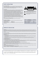
SAFETY INSTRUCTIONS General safety instructions Do not remove the cover or back. No user serviceable parts inside; refer servicing to qualified personnel. To reduce the risk of fire or electrical shock, do not expose this appliance to rain or moisture, direct sunlight or excessive heat from sources such as radiators or spotlights. The free flow of air inside and around the unit must always be ensured.
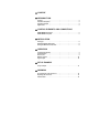
CONTENT INTRODUCTION Features . . . . . . . . Functional description Functional principle . Applications. . . . . . . . . . . . . . . . . . . . . . . . . . . . . . . . . . . . . . . . . . . . . . . . . . . . . . . . . . . . . . . . . . . . . . . . . . . . . . . . . . . . . . . . . . . . . . . . . . . . . . . . . . . . . . . . . . . . . . 5 5 5 5 SMART MERGE front panel . . . . . . . . . . . . . . . . . . . . . . . . . SMART MERGE rear panel . . . . . . . . . . . . . . . . . . .
�� � � � � � � � � � � � � � �������������������������������������������������������������������� INTRODUCTION Thank you for purchasing a SMART MERGE, 8-Channel Digital Line Mixer, from MUTEC.
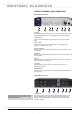
������� �������� ������������� �������������������������������������������������������������������� CONTROL ELEMENTS AND CONNECTIONS SMART MERGE front panel 2 1 3 4 5 6 8 7 1 POWER This red LED lights up when the device is turned on using the main switch at the rear (POWER) and the country-specific mains voltage is supplied. 2 INPUT STATUS These four red LEDs indicate the signal status for the respective digital input.
������� �������� ������������� �������������������������������������������������������������������� 2 S/PDIF COAX IN These four input interfaces receive an unbalanced, digital audio or empty frame signal in coaxial S/PDIF format, electrically based on the specifications of the IEC 60958 standard (cinch connector). The input impedance is 75 Ω.
� � � ������ � � � ������������ �������������������������������������������������������������������� INSTALLATION Do NOT expose the unit and its accessories to rain, moisture, direct sunlight or excessive heat produced by such heat sources as radiators or spotlights! Setting up The device should be placed as close as possible to the devices to which it will be connected in order to reduce the amount of cable needed.
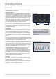
� � � ��� � � � ������������ �������������������������������������������������������������������� OPERATION Thanks to its clear structure and fully automatic functioning, operating the SMART MERGE is incredibly easy. Connecting the devices When selecting which of the SMART MERGE digital audio inputs to use to connect the devices please note that there are two interfaces available for each of inputs 1 + 2.
� � � ��� � � � ������������ �������������������������������������������������������������������� Monitor-Status-LEDs Monitor function In addition to individual listening, the monitor function integrated in the SMART MERGE also enables the patching of the individual input signals on the AES/EBU master output. Both of these functions are selected using the SINGLE / MASTER switch.
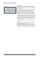
� � � � � � � � � � � �� ������������ �������������������������������������������������������������������� SET-UP EXAMPLE This diagram shows SMART MERGE as a digital submixer for various musical instruments. MIDI control Digital outputs of various clock rates Synthesizer / Sampler Synthesizer / Sampler Synthesizer / Sampler Synthesizer / Sampler MAC / PC Digital Audio Workstation Digital Audio at 48.0 kHz To one input channel of mixing desk Digital Mixing Desk 48.
�� � � � � � � ������������ �������������������������������������������������������������������� APPENDIX Pin assignment of the connectors Mains 1 2 3 1 Live, phase (brown; USA: black) 2 Protective earth (green/yellow; USA: green) 3 Neutral (blue; USA: white) AES/EBU IN (XLR) S/PDIF IN (Cinch) Word Clock i/o (BNC) 1 2 1 2 2 1 3 1 Audio ground 2 a conductor (hot / +) 3 b conductor (cold / -) 1 Audio signal 2 Audio ground 1 Signal 2 Ground Applies to input and output! Replacing the mains fuse Us
�� � � � � � � ������������ �������������������������������������������������������������������� Technical data S/PDIF INPUTS Interface 4 x coaxial (Cinch/RCA), unbalanced, input impedance 75 Ω, 200mV 2V, IEC 60958 1 x optical, Toshiba ToslinkTM, EIAJ RC-5720, IEC 60958 Resolution 16 24 Bits Lock range Every audio clock rate from 32.0 kHz to 108.
������������������������������������������������������������� ���������������������������������������������������������������������������������������������� ���������������������������������������������������������������������� ������ ���� ���� ��������� ���������������� ������������������� ���� ������������������������