KB3100 SERIES PROGRAMMABLE KEYBOARD USER’S MANUAL Rev.
SOM E IMPORTANT NOTES FCC NOTES This equipment generates, uses, and can radiate radio frequency energy and, if not installed and used in accordance with the instructions manual, may cause interference to radio communications. It has been tested and found to comply with limits for a Class A digital device pursuant to subpart J of Part 15 of FCC Rules, which are designed to provide reasonable protection against interference when operated in a commercial environment.
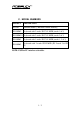
TABLE OF CONTENTS O V E R V IEW . . . . . . . . . . . . . . . . . . . . . . . . . . . . . . . . . . . . . 1 - 1 SCOPE . . . . . . . . . . . . . . . . . . . . . . . . . . . . . . . . . . . . . . 1 - 1 FEATURES . . . . . . . . . . . . . . . . . . . . . . . . . . . . . . . . . . 1 - 1 MODEL UMBERS . . . . . . . . . . . . . . . . . . . . . . . . . . . . 1 - 2 PAC K A GE CO N T EN T S . . . . . . . . . . . . . . . . . . . . . . . . 2 - 1 O P T ION LIST . . . . . . . . . . . . . . . . . . . . . . . . . . . . . .
PREPRINTED KEYS . . . . . . . . . . . . . . . . . . . . . . . . . . 6 KEY CAP . . . . . . . . . . . . . . . . . . . . . . . . . . . . . . . . . . . . 6 P R O G R A M M A B ILITY . . . . . . . . . . . . . . . . . . . . . . . . . 6 POSITION CONTROL KEY . . . . . . . . . . . . . . . . . . . . 6 OUTPUT INTERFACE . . . . . . . . . . . . . . . . . . . . . . . . . 6 MAGNETIC STRIPE READER . . . . . . . . . . . . . . . . . . 6 READER SPECIFICATION . . . . . . . . . . . . . . . 6 CARD DATA FORMAT . . . . . . . . . .
I. OVERVIEW A. SCOPE The KB3100 series is a series of powerful programmable keyboard suitable for application in both IBM PC compatible system and PS2 compatible system, programmable without TSR under DOS, Windows 3.1 and also Windows95/Windows98 environment. This series provides 112 keys (max.) of a comfortable size 18 x 22 mm in 8 x 14 matrix and a 6 position control key which is capable of sending answer back codes according to the position of the key. B.
C. MODEL NUMBERS MODEL # DESCRIPTION KB3100 Standard model (8 KB non-volatile memory) KB3100M2 Keyboard with 2 tracks ISO7811 MSR (tracks 1 & 2) KB3100M2/3 Keyboard with 2 tracks ISO7811 MSR (tracks 2 & 3) KB3100M3 Keyboard with 3 tracks ISO7811 MSR (tracks 1, 2 & 3) KB3100MJ Keyboard with 2 tracks JIS II MSR (JIS I track 2 & JIS II) NOTE: PS/II or PC interface selectable.
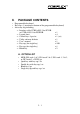
II. • • • PACKAGE CONTENTS Programmable keyboard Key clip x 1 (mounted at bottom of the programmable keyboard) Accessory bag including: ⇒ Interface cable CCBLA-055-2 for PC KB or CCBLA-055-1 for PS/II KB x1 ⇒ Legend sheet x4 ⇒ Control keys 4 pcs/set x 1 (set) ⇒ Utility software diskette x1 ⇒ User’s manual x1 ⇒ Key cap (for single key) x 100 ⇒ Key top (for single key) x8 ⇒ Blank key x2 A.
2-2
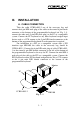
III. INSTALLATION A. CABLE CONNECTION Take the cable CCBLA-055-2 out of the accessory bag and connect the 6 pin DIN male plug of the cable to the central 6 pin female connector at the bottom of the programmable keyboard (ref. Fig. 3-1), connect the other end (5 pin DIN male plug) to the PC or a compatible system.
B. KEYTOP LAYOUT The basic layout of this programmable keyboard is a matrix with 8 rows and 14 columns to provide maximum 112 keys with the 6 position control key. However, there are means for the user to break the monotony and to improve the efficiency in application of this programmable keyboard.
Furthermore, there are blank keys available which the user can use to form visible partitions or clusters of key tops on the programmable keyboard. When the user wants to make a group of keys on the programmable keyboard clearly separated from the rest part of the keyboard for certain specific application, he/she can use the blank keys to replace the normal individual keys around the area. The top surface of a blank key is at the ground level of the key stroke for other keys (ref. Fig. 3-7).
Double key LP L4 Blank keys L3 POWER MAGNETIC STRI PE READER LO L2 L1 Quad key Numerical keys Fig.
IV. APPLICATION A. KEYBOARD CONSTRUCTION 6 position key Power-on LED 6 position key switch MSR indicator LP LP L4 L4 LO LO L3 L3 POWER POWER L1 L2 L2 L1 MAGNETIC MAGNETIC STRIPE STRIPE READER READER MSR slot 14 x 8 push keys Fig. 4 - 1 This keyboard is constructed of three parts on the top surface (ref. Fig. 4-1).
table for the 112 push keys applies, while the definitions of the same key within different pages can be programmed so absolutely independent to provide instant menu change over. This turnable electronic key switch is delivered with a set of 4 pcs keys, each marked as “PRG”, “REG”, “Z” and “GT”. The effective range of each of the 4 keys can be illustrated by the following table and drawing.
B. PRELOADED PATTERN As the KB3100 series satisfies so many application requirements easily, it is naturally impossible to give a definite set of key definitions to serve most of its application. However, this keyboard is preloaded with a particular pattern on the page LP before it is delivered. Please refer to the print-out on next page for the key definition of each location of this preloaded pattern.
Print Scroll Screen Lock + – × ÷ Esc F1 F2 F3 F4 F5 F6 Esc F7 F8 F9 F10 F11 F12 ← ↓ → ~ ` ! 1 @ 2 # 3 $ 4 % 5 ^ 6 & 7 * 8 ( 9 Tab Q W E R T Y U I Cap A S D F G H J Shift Shift Z X C V B N Ctrl Alt ↑ Ins Home PgUp Del End PgDn ) 0 _ - + = ï O P { [ } ] | \ K L : ; ” ’ Enter Enter M < , > .
C. MSR (Magnetic Stripe Reader) The MSR slot is near the upper edge of the Programmable Keyboard. The MSR indicator LED is located at the upper left corner of the block containing the electronic key. There are four choices of the reader types – ISO 1,2 or 2,3 dual tracks, ISO triple tracks and JIS types. For card reading, be sure to insert the card to the bottom with magnetic stripe of ISO card or JIS I track 2 facing downward.
JIS card The side with JIS II magnetic stripe toward user Fig.
V. PROGRAMMING THE KEYBOARD A. EASINESS IN PROGRAMMING The programmable keyboard series KB3100 is a very powerful programmable keyboard. It can be used under any environment that any PC or PS2 keyboard can be applicable with its immense programmability. However the programming could seem to be a little bit more restrictive yet very convenient. The KB3100 series can be programmed under W indows95, W indows 3.1, and DOS environment through application of the utility diskette attached in the accessory.
PC or PST SYSTEM PROGRAMMABLE KEYBOARD EXT. KB PORT PC or PS2 KEYBOARD Fig. 5 - 1 Preparations 1. ANSWER BACK CODE Programming the answer back codes of the 6 position electronic key-lock is also very easy as they are included in the keyboard programming with the locations coded as “KLP”, “KL0”, “KL1”, “KL2”, “KL3” and “KL4” in the key-layout map of page L1.
2. HOT KEY PROGRAMMING The POSIFLEX programmable keyboard KB3100 series supports the “hot key programming” method which is most useful in instant modification of a few keys in a preprogrammed keyboard without entering the more sophisticated programming utility. Of course, the user may also use this feature to program through out all 112 keys by 5 pages (LP and L1 to L4) at will.
programmed. If the “hot key” is pressed for the second time or the “Esc” key is pressed prior to the press of the key on the programmable keyboard, this mode will be aborted immediately. The user should not enter the “hot key programming” mode when the programmable keyboard is already fully loaded (no more free memory for further programming) by the key contents previously programmed. c.
d. Exit “hot key program m ing” mode After the intended content of the key is completely entered, the user shall press the “hot key” again to notify the end of “hot key programming”. The programmable keyboard will give one beep to signify the normal exit of the “hot key programming” mode.
5-6
VI. SPECIFICATIONS CONSTRUCTION: CASE MATERIALS: POWER ON LED: KEY SWITCH TYPE: KEY STROKE TRAVEL: KEY TOP SIZE: PREPRINTED KEYS: KEY CAP: PROGRAMMABILITY: • METHOD: • COVERAGE: • CODE TYPE: • LANGUAGE: Spill-proof, 112 keys + 6 position control key ABS 94V0 Green membrane plus rubber dome 3.2 mm 18 x 22 mm for normal keys (ivory) “.”, “00”, “0” to “9” 18 x 22 mm transparent Software under DOS, W indows 3.
POSITION CONTROL KEY: • 6 positions (LP, L0, L1, L2, L3, L4), key extractable at L0 and L1 • Hardware lock off all keyboard input after return signal sent at L0 • Capable of giving programmable answer back code of each position on position change of the key • Capable of giving programmable answer back code of each position on receiving a specific code (E7h) from host computer OUTPUT INTERFACE: • 6 pin DIN female connector: connect to host computer • 5 pin DIN female connector: connect to input PC keyboard o
Reader specification Applicable card type ISO 7811 Card feed method Manual Card feed direction B i-direction Read / write function Read only Card feed speed 5 to 55 inches/sec. Error rate Less than 0.5% JIS X 6302 Manual Uni-direction Read only 100 ~ 1200 mm/sec. Less than 0.
RELIABILITY INFORMATION: 15,000,000 strokes min. • Push key switch:........ 100 years min. • Memory:.................... MSR head life: .......... 300,000 passes min.