Front Tine Rototiller Operators Manual Transport Position Operating Position Includes Models FT6000X92A F-041303L
F041303L 2
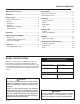
MODEL INFORMATION MODEL IDENTIFICATION .............................................. 3 ADJUSTMENTS ........................................................... 12 Belt Tension Adjustment ............................................ 12 Depth Regulator Lever ................................................ 13 WARRANTY .................................................................... 4 SAFETY RULES ............................................................. 5 Owner's Responsibility .....................
WARRANTY Thank You . . . for purchasing an Murray front tine rototiller. We guarantee that this front tine rototiller conforms to applicable North American safety standards, and have worked to ensure that it will meet your exacting standards for usability and durability. With proper care, your rototiller will provide many years of service. Please take time to read this manual carefully to learn how to operate and service your rototiller correctly.
SAFETY RULES OWNER'S RESPONSIBILITY CAREFULLY READ THIS MANUAL AND FOLLOW ALL INSTRUCTIONS. Safe and effective use of the rototiller is the owner's responsibility. Be familiar with all controls before operating the tiller. Your tiller is equipped with a safety device that enables you to stop the tines quickly in an emergency. Learn how the drive safety control lever works and how to control the tiller at all times. 1. Read and follow all safety instructions. 2.
SAFETY RULES OPERATION Never allow bystanders near the unit. Never operate the tiller without good visibility or light. Never operate the tiller without guards, covers, and hoods in place. Take all possible precautions when leaving the machine unattended. Disengage drive control lever, stop the engine, wait for all moving parts to stop, and make certain guards and shields are in place. Keep hands, feet, and clothing away from rotating parts. Keep clear of tiller tines at all times.
SAFETY RULES SAFETY DECALS This rototiller unit has been designed and manufactured to provide you with the safety and reliability you would expect from an industry leader in outdoor power equipment manufacturing.
FEATURES drive safety control lever forward cable hand knob T belt guard 3-way adjustable tine widths The advantage of the MURRAY gear drive rototiller over other front tine tillers, is the exclusive – unfolding and flexible drag bar. This gives– 1the Murray gear drive tiller its stability and its versatility. For easy transport, fold the wheels under the engine. During operation, the wheels unfold back and the drag bar folds down.
UNPACKING AND ASSEMBLY UNPACK TILLER 1. Open top of carton and remove handlebar assembly. The right and left sides of your rototiller are determined from the operating position as you face the direction of forward travel. CAUTION Do not try to lift the rototiller from the carton. 2. Cut open end of carton and remove machine: a. Tines are pre-assembled at 21 width. Sharp edge of tine will be away from operator at top or face down at front of machine.(Figure 2) b.
UNPACKING AND ASSEMBLY INSTALL THE DEPTH REGULATOR LEVER FILL ENGINE CRANKCASE 1. Install the depth regulator lever through hole in bracket from the bottom up with curve to rear of unit and secure with detent pin. Engine is shipped from factory without oil. You must add engine oil before starting engine. 1. Add oil according to engine manual. Do not overfill. Use a clean, high quality detergent oil. Container must be marked A.P.I. Service SF - SJ. Use no special additives with recommended oils.
CONTROLS DRIVE SAFETY CONTROL LEVER CAUTION Engage tines into forward, releasing returns machine to neutral. This information is provided here only to introduce the controls. DO NOT START THE ENGINE AT THIS TIME. Starting and operating instructions are given on page 11. Please read this section and all operating and safety instructions before starting your tiller. Pulling down on drive safety control lever engages the tines.
ADJUSTMENTS BELT TENSION ADJUSTMENT beehive spring Proper belt tension is critical to good performance. After half hour of operation, all cables may have to be adjusted due to initial stretch. Thereafter, check tension after every 2 hours of operation. 1/4 stretch To increase belt tension: upper jam nut 1. Loosen upper jam nut. Turn nut up cable in 1/8" increments. 2. Tighten lower jam nut. lower jam nut 3. Check adjustment.
ADJUSTMENTS DEPTH REGULATOR LEVER Tilling depth is controlled by the height of the depth regulator lever. depth regulator lever To adjust tilling depth: 1. Remove detent pin. detent pin 2. Raise the depth regulator lever to position tines at chosen tilling depth. 3. Align hole in depth regulator lever with hole in depth regulator bracket and replace detent pin. Figure 8 CAUTION Do not adjust tilling depth unless drive safety control lever is released to the neutral position.
OPERATION PRE-START INSPECTION 1. Make sure all safety guards are in place and all nuts and bolts are secure. Engine is shipped from factory without oil. You must add engine oil before starting engine. 2. Check oil level in engine crankcase. See your engine manual for procedure and specifications. 3. Inspect air cleaner for cleanliness. See your engine manual for procedure. START-UP The controls required to start and run the rototiller are located on the engine and are marked "Choke" and "Throttle". 4.
OPERATION TILLING DANGER Always keep hands and feet clear of rotating machine parts. 1. Adjust the depth regulator lever to desired tilling depth. NOTE: Raise depth regulator lever up one hole at a time, testing tiller operation after each raise. Raising depth regulator lever too high can result in loss of control of tiller! WARNING Temperature of muffler and near by areas may exceed 150° F. Avoid these areas. 2. Move the throttle control to fast. 3.
NORMAL CARE SCHEDULE Your rototiller has been designed and produced by the industry's leading manufacturer of outdoor power equipment to provide you with years of reliable operation. Keeping your tiller in top running condition will prolong its life, and help you obtain optimum performance whenever you wish to till your garden. Please read this normal care schedule, and observe these recommended care operating intervals to extend the life of your unit.
NORMAL CARE SERVICING THE ROTOTILLER Belt Replacement General 1. Turn off engine. Engine must be cool. The following information will help you make the necessary checks and perform the procedures required to follow the normal care recommendations made for your rototiller unit. 2. Remove spark plug wire from spark plug and secure. 3. Remove belt guard. (Fig. 11) 4. Remove dirt shield from bottom of tiller. (Fig.
NORMAL CARE CAUTION Do not operate tiller before reading the engine manual provided in the parts packet. Engine is shipped from factory without oil. You must add engine oil before starting engine. WARNING Temperature of muffler and near by areas may exceed 150° F. Avoid these areas. Check or Fill Engine Oil 1. Add oil according to engine manual. Do not overfill. Use a clean, high quality detergent oil. Container must be marked A.P.I. Service SF - SJ. Use no special additives with recommended oils.
NORMAL CARE Check Tiller Transmission Grease Clean Tine Axle Shaft 1. Turn off engine. Engine must be cool. 2. Remove spark plug wire from spark plug and secure. 3. Remove all vegetation, string, wire, and other material that may have accumulated on the axle between the inside set of tines and the seal on the transmission housing. Tiller transmission is shipped from factory with the proper amount of grease. To add grease, remove both high and low grease ports.
STORAGE PREPARE FOR STORAGE CAUTION Follow the steps below to prepare your tiller for storage. Read your engine manual for detailed instructions on preparing the engine for storage. Do not store tiller in an non-ventilated area where fuel fumes may reach flame, sparks, pilot lights or an ignited object. Drain fuel outdoors away from any ignition sources. Use only approved fuel containers. 1. Protect wheels and axles from rust: - Coat the axles lightly with axle grease. 2.
TROUBLESHOOTING AND REPAIR TROUBLESHOOTING GUIDE CAUTION While normal care and routine maintenance will extend the life of your rototiller, prolonged or constant use may eventually require that service be performed to allow it to continue operating properly. The troubleshooting guide below lists the most common problems, causes and remedies. Practice safety at all times.
HANDLEBAR ASSEMBLY FT6000X92A 2 1 3 4 5 6 8 6 9 11 10 10 13 14 KEY NO. 1 2 3 4 5 6 8 9 10 11 13 14 15 F-041303L PART # AR3262E701 028X23 AR3261 15x146 AR53530 15x147 7401038 AR3108A 094068 AR3264E201 315288 01x137 015X84 15 14 DESCRIPTION FRONT TINE DRIVE LEVER, WELDED PUSH CAP, 3/8 Dia. FRONT TINE TENSION SPRING LINK NUT-Nyloc, #10-24 SPRING-Bee Hive, Forward Cable Adjust NUT-Jam, 5/16"-24 TOP HANDLE ASSEMBLY CABLE ASSEMBLY WITH FERREL KNOB - Wing BOTTOM HANDLE BOLT 5/16-18 UNC X 1.
FT6000X92A SHAFT ASSEMBLY 1 2 3 4 5 6 51 13 16 18 7 61 19 1 1 18 62 1 19 20 19 19 17 17 KEY NO. 1 2 3 4 5 6 7 13 16 17 18 19 20 51 61 62 F-041303L PART # 37X138 001X64 018X15 17x146 AR746 AR3179 ARM1000 2001022 AR3323E701 001X75 AR3324E701 015X88 AR3326E701 01X199 018X32 15X116 DESCRIPTION BELT-Forward CAPSCREW-Hex Hd, 5/16-24 x 3/4 LOCKWASHER-Spring, 5/16 WASHER, .34 ID X 1.
FT6000X92A MOTOR MOUNT & HOOD ASSEMBLY 1 3 2 4 10 10 11 9 12 5 6 7 8 17 9 15 16 16 19 21 20 19 24 27 20 30 44 25 26 29 28 27 39 41 6 35 36 30 20 33 37 9 38 38 F-041303L 24 36 43 9
MOTOR MOUNT & HOOD ASSEMBLY KEY NO.
______________________________________________________________ ______________________________________________________________ ______________________________________________________________ ______________________________________________________________ ______________________________________________________________ ______________________________________________________________ ______________________________________________________________ ______________________________________________________________ ________
MURRAY, INC. CENTRAL PARTS DISTRIBUTORS BILLIOUS, INC. 1343 South Main St. Porterville, CA. 93257 (559)784-4102 or 1-877-245-5468 FAX 1-800-266-7337 Arizona, California, Hawaii, Nevada BROWN & WISER, INC. 9991 S.W. Avery Street Tualatin, OR.