CANdrive™ Module Installation and Operations Manual 00-02-0618 04-10-07 Section 78
In order to consistently bring you the highest quality, full featured products, we reserve the right to change our specifications and designs at any time. The latest version of this manual can be found at www.fwmurphy.com. Warranty - A two year warranty on materials and workmanship is given with this FW Murphy product. A copy of the warranty may be viewed or printed by going to www.fwmurphy.com/support/warranty.htm.
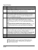
Table of Contents General Information................................................................................................................ 1 Introduction ..................................................................................................................1 Installation Instructions.......................................................................................................... 2 Configuration....................................................................................
(THIS PAGE INTENTIONALLY LEFT BLANK)
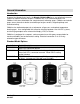
General Information Introduction As part of the MurphyLink® family, the Murphy CANdrive™ offers a cost effective instrument solution for modern electronic engines. CANdrive acts as an interface between ECU CANbus/J1939 transmitted data and standard electric indicating gages. CANdrive and electric gages are an alternative solution to retrofitting of engine senders, magnetic pickups and associated wiring. CANdrive has dedicated outputs for a tachometer, oil pressure, and coolant temperature electric gages.
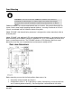
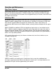
Installation Instructions Configuration CANdrive modules are supplied with 5 circuit board links soldered in place. These wire links, labeled L1 through L5, are located on the back side of the unit. The links allow configuration of operating options by snipping the appropriate wire according to the following configuration table. WARNING: The configuration links are one-time breakable and are not replaceable. Care must therefore be taken to select the correct options before cutting links.
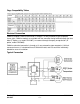
Gage Compatibility Tables Electrical Connection CANdrive modules electrical connection is through a 12-way automotive type receptacle shown right. CANdrive models are available with the connector facing forward through the front label (‘F’ option, e.g. model CDV100F), or rearward through the epoxy encapsulation (‘R’ option, model CDV300R). CANdrive electrical connection is through a 12-way automotive type receptacle.
Terminal Functions PIN 1 2 3 4 6 7 5 8 9 10 11 12 Function Negative DC, power supply Positive DC, power supply Negative DC, gage common return CANdrive modules are supplied for use with 12V (7 to 16V) DC operation. If 24V (19 to 30V) DC operation is required, remove (cut) rear link L2. Connect a 1 Amp anti-surge fuse in the positive DC line (pin 2).
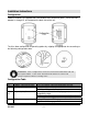
Panel Mounting WARNING: Do not install the CANdrive module near exhaust manifolds, turbochargers or other engine locations that might exceed the maximum allowable operating temperature of 185°F (85°C). CANdrive modules are surface-mounted with four no.4 screws, fixing center dimensions as shown. Select screw length according to panel thickness, ensuring a maximum of 1/2 inch (13mm) screw depth into the CANdrive module fixing holes.
Operation and Maintenance Gage Driver Outputs Gage outputs operate when CANdrive module reads valid J1939 data for engine speed, oil pressure and coolant temperature. If CANdrive module stops receiving valid data, the gage outputs are maintained at the last known value for approximately five seconds, after which time the outputs are turned off. Indicating LEDs All standard models have a green CAN status LED.
Maintenance CANdrive modules have no user-serviceable parts. Maintenance is therefore limited to the following preventative checks: • Check that electrical connections are secure. • Check that the CANdrive module is securely mounted and kept free from exposure to water or build up of excessive dust/dirt. The front label and casing may be wiped with a clean, damp cloth. Do not use cleaning solvents.
Specifications Power Supply • Operating voltage: • 12V range (link L2-in place) • 24V range (link L2-cut) 7-16 VDC 19-30 VDC • Current consumption: • CDV100F: 25mA typical • CDV300R: 50mA, typical (2 LEDs lit) Inputs • CANbus: • SAE J1939 protocol, Input fitted with 120 Ohm terminating resistor, removable by cutting link L1.
MURPHY, the Murphy logo, and CANdrive are registered and/or common law trademarks of Murphy Industries, Inc. This document, including textual matter and illustrations, is copyright protected by Murphy Industries, Inc., with all rights reserved. (c) 2007 Murphy Industries, Inc. Other third party product or trade names referenced herein are the property of their respective owners and are used for identification purposes only.