
User`s manual

-7-
type, KW and KWHr are displayed on the Multifunction display. To scroll between these readings, press the
Menu push button. To exit the Fault Log, press the SELECT push button.
7.2 ERASING THE FAULT LOG
To erase the Fault Log, enter the menu, scroll down until “ERSFLT” is displayed and press the SELECT push
button. The SURF module prompts you to confirm your request by displaying the “RUSURE” message. To
cancel the request, press the UP push button. To confirm the request, press the DOWN push button.
8 TIME SWITCH OPERATION
The time switch manages the operating time of the genset , daily and weekly. Two parameters control the
daily time switch: T-Rdy and T-sdby. T-Rdy sets the time at which the genset becomes ready. T-sdby sets the
time at which the genset goes to standby mode. If genset is required to be in ready mode all day then set
T-Rdy to ALLTIM (T-Sdby will no longer show). Rdyday controls the weekly operation. Under Rdyday, if ALL
is set to Y then the genset will be ready all week long. Otherwise, the genset will be ready only in days set to Y.
It will be in standby in days set to N. As a result, the genset will be ready during the hours set by T-Rdy and
T-Sdby only on days set to Y under Rdyday.
8.1 REMOTE CONTROL TERMINAL FUNCTION DESCRIPTION
In SURF-AMF with remote control set to RQS: when remote control is active, it overrides time switch
setting and forces the genset into ready mode.
In SURF-AMF with remote control set to SUP: when remote control is active, it overrides time switch
setting and forces the genset into standby mode.
In SURF-AUTO with remote control set to RQS: When remote control is active and genset in ready mode,
the genset is started. Otherwise, the genset is stopped.
In SURF-AUTO with remote control set to SUP: when remote control is active and genset in ready mode,
the genset is stopped.
9 FRONT PANEL DESCRIPTION
9.1 MEASURED AND DISPLAYED PARAMETERS
Voltage, current and frequency measurements correspond to the source feeding the load.
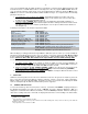
The currents on the three phases are measured and displayed simultaneously using the following
format.
Current range Format
0 to 99.9A ##.# in A
100 to 999A ### in A
1000 to 1999A 1### in A
2000 to 9999A #.## in KA
The line-neutral and line-line voltages are all measured. The voltage displayed is either fixed on one
voltage or allowed to scroll automatically between all six voltages (rn, sn, tn, rs, st, tr). The Menu push
button is used to switch between the two display modes.
The frequency is measured and permanently displayed.
The hour meter is measured (or taken from the CAN bus if it is enabled) and permanently displayed.
The engine temperature and oil pressure are measured (or taken from the CAN bus if it is enabled) and
permanently displayed
The battery voltage is measured and permanently displayed
The Multifunction portion of the LCD displays the number of hours since the last oil change, the active
power in KW for the source feeding the load, the energy in KWh for the genset, Utility and Genset
status and the CAN readings: RPM, L/H, L, Add and DTC error messages. To start or stop scrolling
between these messages, press the push button of the current operating mode.
9.2 FRONT PANEL LEDS
Four Leds are used to indicate the operating mode.
Six input Leds used to indicate the status of the inputs.
Utility supply has one red led. Led ON indicates that the Utility supply is within the acceptable limits, the
phases are all present and in the right sequence. Led OFF indicates absence of Utility. Led blinking
indicates an anomaly on the Utility.
Utility contactor has one green led to show its status.