
User`s manual

-4-
Manual Mode: This mode is entered when the Manual/Down push button is pressed. In this mode, the
module will start the genset and engage the load. If, originally, Utility was feeding the load and the
genset has no fault, Utility will continue feeding the load until the genset is done warming up
(2)
. The load
is disengaged and a transfer dead time
(3)
is counted before the genset engages the load. If the genset
has a fault, then Utility would disengage the load immediately.
Utility Only/Standby Mode: This mode is entered when the Utility/Select push button is pressed. In
this mode, if Surf type is Surf-AMF, the Utility would feed the load when it is present. If Utility is absent
or Surf type is Surf-AUTO, the genset will not be requested. If the genset was feeding the load before
switching to this mode, the load will be disengaged.
Auto Mode: This mode is entered when the Auto/Up push button is pressed. In this mode, Utility will
feed the load if present. If Utility is absent, the genset will feed the load if no faults exist on it and if the
remote control signal is active. If the genset was feeding the load and the remote control signal turns
off, the genset would count the delay set by oFF (for Surf-AUTO) – MRT (for Surf-AMF) before
disengaging the load. If the Utility is restored while the genset is feeding the load, Genset disengages
the load after Restoration delay. Utility will engage after transfer dead time.
Following is a description of the start sequence of the genset:
1. Once the remote control input receives a start signal, the response delay (set by RSP) is counted.
2. After the elapse of the response delay, the preheat relay (if present) is engaged for a time delay set by
PRH.
3. A starting sequence of a preset number of attempts ATT will initiate.
4. The Electric Valve is engaged for 0.25 sec before the Starter.
5. If the start signal is removed before the engine starts, all timers are reset and the module is ready for a
new sequence.
6. Cranking is disconnected when any of the following condition becomes valid:
a. The measured frequency exceeds CrF.
b. A voltage exceeding dcd (if not set to N) appears on the Dynamo input.
c. The oil pressure switch opens (given that boP is not set to Y) and its preset delay has elapsed.
d. The analog oil pressure measurement exceeded the value set by LoA (if not set to N).
e. For Volvo engines, when a running indication is received through the CAN bus or the RPM exceeds
500.
7. If the engine fails to start after the preset number of attempts, the Alarm output is activated, the LCD
alarm symbol ( ! ) blinks and the Multifunction Display on the LCD would indicate a start fail error
(St Fail). Otherwise, the engine enters the running state and the running symbol (
) turns on.
8. After elapse of the warm-up delay, set by WuP, the load contactor is engaged via terminal Contactor-G
and the green load led is activated. If one of the Outputs is set to Cont-G2, then Cont-G2 would be
engaged 5 seconds after the first Contactor.
9. All protections are enabled when the engine is running and after the elapse of the fault bypass time set by
bYP.
10. Once a fault occurs, the load is shut down. Some faults require the engine to cool before shutting (high
engine temperature, overload). Other faults would directly shut the engine. Alarm output and the
corresponding fault symbol on the LCD are activated. The Multifunction Display would explain the fault. If
CAN bus is enabled, the Multifunction display will show the DTC (J1939 protocol error code) description
of the fault received from the CAN bus.
11. When the start signal on the genset is removed, the load is shut down after the elapse of the delay set by
oFF (for Surf-AUTO) – MRT (for Surf-AMF). The engine is shut down after the elapse of the cooling time
set by CoL.
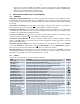
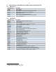
4 PROGRAMMABLE OUTPUTS
SURF has a total of six outputs (Output 1 6) that could be programmed to any of these functions: Preheat,
Starter, Electric Valve, Utility Contactor, Genset Contactor, Alarm, Cut-off, Pre-alarm, Genset Contactor 2,
Dummy Load, Overload, Start Fail and Auto Mode. Users can easily change the function of these outputs from
the menu, parameters O1 O6. The user can also disable the output by setting the corresponding parameter
to Not Assigned (N/A). Following is a description of each function:
Preheat (PRE) Function when one of the outputs is set to Preheat, the PRH parameter in the menu
becomes visible and takes the default value 0. The preheat output is activated when the genset finishes
counting the response delay and remains on for a delay set by PRH.
2
Warm Up delay is presettable in the menu
3
Transfer dead time is presettable in the menu