
User`s manual

-12-
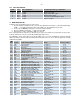
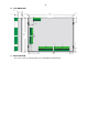
10.2 LEDS DESCRIPTION
Led No. Color Input configuration Correspondent factory configuration
1 Green Remote Control signal Remote Control signal
2 Red
IP1 signal
Oil pressure signal
3 Red
IP2 signal
Engine temperature signal
4 Red
IP3 signal
Oil temperature signal
5 Red
IP4 signal
Low Fuel level Normally Open signal
6 Red
IP5 signal
Lamp Test signal
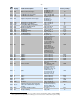
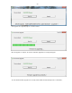
11 MENU DESCRIPTION
Follow the steps described below to access the menu:
1. Press the Menu Push button for three seconds: The alphanumeric characters on the LCD would display
“PSW – “. You will be prompted to enter a three-digit code. The default password is 000.
2. Use the UP and DOWN push buttons to scroll to the desired number.
3. Press the SELECT push button. “*” replaces the first digit.
4. Repeat steps 2. and 3. until all three digits are entered.
If the entered password is valid, the user will have access to the menu below. If no push buttons are pressed for
5 minutes while in the menu, the system will automatically exit the menu.
The SMS Alias column in the table represents the SMS code to use when modifying the parameter through
SMS. In the Range column below, the number between brackets is the one to use when the parameter is being
modified through SMS.
SMS
Alias
Display Parameter Description Range Factory setting
A01
RSP Response delay 0 to 255 sec 5 sec
A02
PRH Preheat delay 0 to 255 sec 0 sec
A03
STA Starter time 0 to 255 sec 5 sec
A04
bET Time between trials 0 to 255 sec 12 sec
A05
ATT Number of Attempts 0 to 255 3 Att
A06
bYP Fault bypass delay 0 to 255 sec 15 sec
A07 WuP Warm-up delay 0 to 255 sec 10 sec
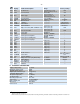
A08
MRT
oFF
Mains Restoration delay (AMF only)
Off delay (AUTO only)
0 to 255 sec 10 sec
A09
XFR Transfer dead time (AMF only) 0 to 255 sec 0 sec
A10 CoL Cooling delay 0 to 255 sec 30 sec
A11
Cut Cut-Off time N (0), 1 to 255 sec 10 sec
A12
CrF Crank Disconnect Freq. 0 to 255 Hz 15 Hz
A13
UoF Utility Over Frequency (AMF only) N (0), 1 to 255 Hz 55 Hz
A14
UoFd Utility Over Freq. delay (AMF only) 0 to 99 sec 2 sec
A15
UuF Utility Under Frequency (AMF only) N (0), 1 to 255 Hz 45 Hz
A16
UuFd Utility Under Freq. delay (AMF only) 0 to 99 sec 5 sec
A17
UoV Utility Over Voltage (AMF only) N (0), 1 to 255 V 240 V
A18
UoVd Utility Over Volt. delay (AMF only) 0 to 99 sec 3 sec
A19 UuV Utility Under Voltage (AMF only) N (0), 1 to 255 V 200 V
A20
UuVd Utility Under Volt. delay (AMF only) 0 to 99 sec 5 sec
A21
GoF Genset Over Frequency N (0), 1 to 255 Hz 55 Hz
A22
GoFd Genset Over Freq. delay 0 to 99 sec 2 sec
A23
GuF Genset Under Freq. N (0), 1 to 255 Hz 45 Hz
A24 GuFd Genset Under Freq. delay 0 to 99 sec 5 sec
A25
GoV Genset Over Voltage N (0), 1 to 255 V 240 V
A26
GoVd Genset Over Volt. delay 0 to 99 sec 3 sec
A27 GuV Genset Under Voltage N (0), 1 to 255 V 200 V
A28
GuVd Genset Under Volt. delay 0 to 99 sec 5 sec
A29
CT Current Transformer ratio 0/5 to 9999/5 100/5
A31
oLd Overload % N (0), 1 to 255% 90%
A32 oLdd Overload delay 0 to 99 sec 10 sec
A33
doN Dummy load engage set point N (0), 1 to 255 % 10%
A34
dod Dummy load engage delay 0 to 255 sec 30
A35
doF Dummy load disengage set point N (0), 1 to 255 % 17%
A36
boP Bypass OPS Y (0),1 to 5 sec 1 sec