S. & A.S. LTD AUTOMATIC MAINS FAILURE – SURF-AMF AUTO START – SURF-AUTO ENHANCED USER’S MANUAL FOR H/W VERSION 1.2A FOR S/W VERSION 2.00 1516 Beirut Office: Boutros Building 1st Basement Cheikh-el-Ghabi Street Ghabi Beirut 2068 7808 Lebanon Tel: +961 1 216 994 Fax:+961 1 339 600 Headquarters & Factory: S. & A. S. Building Seaside Road Jieh Chouf Lebanon Tel: +961 7 996 333 Fax:+961 7 996 116 Website: www.sascontrollers.com Technical Support & Email: Tel: +961 71 996 333 support@sascontrollers.
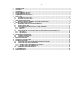
-21 2 3 4 5 6 7 INTRODUCTION ...................................................................................................................................................... 3 FEATURES .............................................................................................................................................................. 3 OPERATION .....................................................................................................................................................
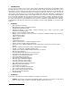
-31 INTRODUCTION This new genset controller series consists of two products: Surf-AMF and Surf-Auto. The Surf-AMF monitors the utility and controls the genset as well as the automatic transfer switch. The Surf-AUTO controls the genset only. However, the two controllers share many common features. Physically, the Surf has a very attractive and slim design. It features isolated measurement of the voltages and frequency on the two sources as well as the current on the load side.
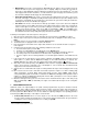
-4 Manual Mode: This mode is entered when the Manual/Down push button is pressed. In this mode, the module will start the genset and engage the load. If, originally, Utility was feeding the load and the genset has no fault, Utility will continue feeding the load until the genset is done warming up(2). The load is disengaged and a transfer dead time(3) is counted before the genset engages the load. If the genset has a fault, then Utility would disengage the load immediately.
-5- 5 Starter (STA) Function is activated while cranking the genset and remains on for a delay set by STA. The minimum value of STA is 1 sec if the oil pressure is bypassed otherwise the minimum value is the oil pressure bypass delay plus one second (boP+1). Electric Valve (EVA) Function if present should be defined at Output 2 since the dynamo excitation is physically connected to this output.
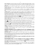
-6Users can communicate with the SURF module by connecting it to a PC through an RS232 Serial Port, USB Port, Ethernet Port or a GSM Modem. When connecting from a PC, the program SURF Control allows the users to view and control the engine and to access the SURF parameters. When the parameter Mod is set to GSM, the user can also communicate with the SURF via SMS messages. To set up this feature, the following parameters must be set: 1.
-7type, KW and KWHr are displayed on the Multifunction display. To scroll between these readings, press the Menu push button. To exit the Fault Log, press the SELECT push button. 7.2 ERASING THE FAULT LOG To erase the Fault Log, enter the menu, scroll down until “ERSFLT” is displayed and press the SELECT push button. The SURF module prompts you to confirm your request by displaying the “RUSURE” message. To cancel the request, press the UP push button. To confirm the request, press the DOWN push button.
-8 9.3 9.3.1 Genset has one red led. Led OFF means that the genset is not requested to start. Led blinking means that the genset has been requested to start or the genset is running with an anomaly. Led ON indicates that genset is running and ready to supply the load. Genset contactor has one green led to show its status.
-9Fail to Start Fault occurs when the engine does not turn on after ATT cranking attempts. ATT is set in the menu. The fault is removed when the Remote Control input is recycled or when Utility is restored. The fault symbol ( ! ) blinks and the Multifunction display indicates a start fail fault by displaying St Fail in the Genset Status page. Emergency Stop occurs when the emergency switch is turned off.
-109.4 9.4.1 DESCRIPTION OF STATUS MESSAGES SHOWN ON MULTIFUNCTION DISPLAY FOR UTILITY (9) Status Message U-AbSt U-RdY U- VX U- FX U- SX U-W 10 U-X 10 U-OnLd 9.4.
-1110 REAR PANEL DESCRIPTION 10.
-1210.2 LEDS DESCRIPTION Led No. 1 2 3 4 5 6 11 Color Green Red Red Red Red Red Input configuration Remote Control signal IP1 signal IP2 signal IP3 signal IP4 signal IP5 signal Correspondent factory configuration Remote Control signal Oil pressure signal Engine temperature signal Oil temperature signal Low Fuel level Normally Open signal Lamp Test signal MENU DESCRIPTION Follow the steps described below to access the menu: 1.
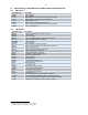
-13SMS Display Alias Parameter Description Range Factory setting A37 oPS Oil Pressure Sensor type V1=VDO type 1 (0) V5=VDO type 2 (1) MU=Murphy (2) V1 A38 A39 LoP LoA Low Oil Pressure Pre-alarm Low Oil Pressure Alarm N (0), 1 to 255 PSI N (0), 1 to 255 PSI N N A40 ETS Engine Temperature Sensor type V1=VD0-1 (0) V2=VD0-2 (1) MU=Murphy (2) PT=PT100 (3) V1 A41 A42 A43 A44 A45 A46 A47 A48 A49 A50 HTP HTA CHT dcd dSd Hib Hbd Lob Lbd LcL High Engine Temp Pre-alarm High Engine Temp Alarm Cooli
-14SMS Display Alias Parameter Description Range Factory setting A67 SPD Speed Select13 PRI=Primary speed (0) SEC=Secondary speed (1) PRI A68 UPW User Password 000 to 999 000 No=no modem (0) LM=Line modem (1) GSM=GSM modem (2) No A69 Mod Modem Type A70 A71 A72 A73 A74 A75 PHONE SITEId dHC IP Adr SubNET GATEWY Phone Number Identification Code DHCP Enabled IP Address Subnet Mask Default Gateway A76 UPH Utility Connection (AMF & AMF/ES only) A77 GPH Genset Connection A78 A79 dATE T
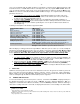
-1513 FIRMWARE UPGRADE 13.1 INSTALLING THE SURF FIRMWARE UPGRADE SOFTWARE In order to upgrade firmware on site, a CD will be provided by S.&A.S.Ltd & the below steps shall be followed: 1. Run file “SAS_Patch.exe” located in “Surf120_PTool\SAS_PTool” folder. 2. Setup the application located in “Surf120_PTool\SAS_PTool \SAS_PTool_Setup” folder 3. SAS_PTool will appear in the programs list. Send it to Desktop as shortcut. 13.2 INSTALLING THE SURF USB DRIVER 1.
-16The “SAS DEV” device will appear in Other Devices, right-click it and choose Update Driver Software. Select “Search automatically for updates driver software”.
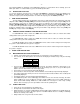
-17Select Install this driver software anyway. The Driver SETUP procedure will be done only once For Windows vista/Win7. So, the driver of any new SURF connected to the PC USB port will be installed automatically. 13.2.2 DRIVER SETUP FOR WINDOWS XP Each time new SURF is plugged into the PC USB port, a “Found New Hardware Wizard” window appears. Select “Install the software automatically (Recommended)” and click next.
-18Select “Continue Anyway”. The driver of the new SURF connected to the PC USB port will be installed automatically. 13.3 FIRMWARE UPGRADE PROCESS Run “SAS_PTool” application. The following window will appear prompting the user that the SURF board is detected on the USB port: Click Open to choose the *.sas file that will be used to upgrade the firmware.
-19- Click upgrade. The upgrade progress is shown as below: Once the upgrade is complete, the footnote “Firmware upgraded successfully” will appear: Then the SURF Firmware upgraded successfully and the SURF will automatically run the new firmware.
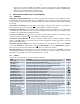
-2014 CASE DIMENSIONS 5.0 mm 11.0 mm 19.0 mm 22.0 mm 196.0 mm 181.0 mm P7 37 136.0 mm P5 25 29.5 mm P6 31 39.0 mm 15 1 7 13 19 P1 P2 P3 P4 6.0 mm WIRING DIAGRAM This section contains the wiring diagram of the SURF-AMF and SURF-AUTO. 19.0 mm 6.0 mm 144.0 mm 136.0 mm 18.0 mm 12.
5 - 33 Vdc 5 6 7 8 9 10 11 12 *: Connected to battery -ve on the engine body NB: R(Alarm), R(G Ld2), R(U Ld), R(G Ld), R(St) and R(EV) relays should all be DC relays with their coil voltage equal to the battery voltage 1 1 I5 (LMP) I4 (LFO) I3 (OTS) I2 (ETS) I1 (OPS) REMOTE CONTROL COOLANT PROBE ANALOG INPUT 4 ANALOG INPUT 3 ANALOG INPUT 2 ANALOG INPUT 1 REF SENSOR 1 LMP 4 LFO 3 OTS 2 CAN_L 2 ETS 1 OPS LINE R G TEMPERATURE SENSOR LINE S G CAN_H 2 OIL PRESSURE SENSOR 31 LIN
2 5 6 7 8 9 10 11 12 NB: R(Alarm), R(G Ld2), R(U Ld), R(G Ld), R(St) and R(EV) relays should all be DC relays with their coil voltage equal to the battery voltage *: Connected to battery -ve on the engine body LMP 4 LFO 3 OTS 2 ETS 1 I5 (LMP) I4 (LFO) I3 (OTS) I2 (ETS) I1 (OPS) REMOTE CONTROL COOLANT PROBE ANALOG INPUT 4 ANALOG INPUT 3 ANALOG INPUT 2 ANALOG INPUT 1 REF SENSOR CAN_L CAN_H 2 OPS O6 (G CONT.