A ® AUTOMATIC ENGINE CONTROLLERS MODELS A88 AND A88-F INSTALLATION MANUAL A88-8916N Revised 01-97 Section 40 (00-02-0196)
TABLE OF CONTENTS SECTION PAGE I INTRODUCTION 1 II IIA IIB IIC SPECIFICATIONS Power Requirements Input Requirements Output Ratings 1 1 1 1 III IIIA IIIB FRONT PANEL DESCRIPTION Description of LED Callouts Description of AOT Switch, Crank Disconnect Control & Rest/Crank Time Control 2 3 IV OPTIONAL HOOKUPS 4 V OPERATION 5 3 LIST OF ILLUSTRATIONS TYPE DESCRIPTION PAGE Illustration Illustration Diagram 1 Diagram 2 Diagram 3 Diagram 4 Diagram 5 Diagram 6 Face Plate, A88 and A88-F Optional
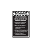
WARNING BEFORE BEGINNING INSTALLATION OF THIS MURPHY PRODUCT ✔ Disconnect all electrical power to the machine. ✔ Make sure the machine cannot operate during installation. ✔ Follow all safety warnings of the machine manufacturer. ✔ Read and follow all installation instructions.
SECTION I: INTRODUCTION A. The Automatic Engine Controller, Model A88 and A88-F is designed to automatically start, monitor and stop electric start engines. The A88 comes in an all-weather case with a 5 foot cable and a plug for connection. The A88-F is the same system, but housed in a panel-mount case with terminals on back for connecting. 8. Crank disconnect circuitry accepts the following inputs: a. breaker or electronic type ignition b. magnetic pickup c. alternator tach d. flywheel alternator e.
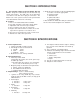
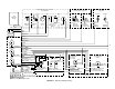
SECTION III: FRONT PANEL DESCRIPTION IGNITION ON CHOKE PICK UP PRESENT OVER CRANK CRANK OIL PRESSURE CRANK DISCONNECT ENGINE TEMP. A88 Automatic Engine Controller CRANK DISCONNECT AUTO (Shown without enclosure) 5s 10s OFF TEST 15s 20s CRANK AND REST TIME A88-F Automatic Engine Controller IGNITION ON CHOKE PICK UP PRESENT OVER CRANK CRANK OIL PRESSURE CRANK DISCONNECT ENGINE TEMP.
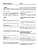
FRONT PANEL DESCRIPTION Along with each description, an attempt has been made to clarify output and input connections according to their functions and terminals or wire color. A. Description of LED Callouts 1. IGNITION The ignition LED will come on when the system receives a signal to start. If the alarm before start is used, this ignition LED will NOT come on until the 5 second alarm goes off. 9. SPARE This LED comes on to indicate cause of shutdown if the spare is used.
SECTION IV: OPTIONAL HOOKUPS In this section the terms Sink and Source are used. Sink: This terms refers to an output that switches to ground to do work. 3. CRANK CONNECTIONS A88-F Terminal Lamp Switch Terminal Lamp Choke No. 3 Violet Sink A88 Wire color Output Operation Summary No. 20 Brown Sink Solenoid to Ground Source B Crank No. 2 White/Red Solen. to batt. pos. Sink 1A 1A No. 18 Yellow After 30 sec. delay Sink Max. Current 1A 5.
SECTION V: OPERATION Refer to Diagrams 1 and 3: Basic Wiring Hookup for correct connections to your engine. Diagram 2 shows wire colors that correspond to the A88 plug and hookup wire, in the event of two colors the first color is the primary color and the other is a tracer color. Diagram 4 identifies the A88-F wiring terminals. Step No. 8, Clutch or Warmup Operation: If a warm up feature is desired see Section IV: Optional Hookups paragraph 5 WARM UP.
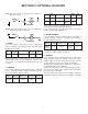
Starter Solenoid Connection Use Only One, 1 amp max Pickup Signal Source Connection Use Only One To Batt. + A88 Mini Auto Starter Remote Annunciator Connection 1 amp max To Batt. + To Batt. + To Batt. + N S 1 2 3 To Starter To Starter Magnetic Pickup A88 cable Fly Wheel ALT.
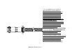
Diagram 2: A88 Wiring Harness 7 Pin 1-wire-Wht/Blk: Breaker ignition I/P Pin 2-wire-Green: Vacuum switch I/P Pin 3-wire-Viol/Wht: Grnd for time delay I/P Pin 4-wire-Grey: Magnetic pickup I/P Pin 5-wire-Blue: Tach alternator I/P Pin 6-wire-Violet: Choke (sink) O/P Pin 7-wire-Wht/Red: Crank (sink) O/P Pin 8-wire-Yellow: Engine running (sink) O/P Pin 9-wire-Grn/Wht: Start I/P Pin 10-wire-Red/Wht: Connect #11 for alarm Pin 11-wire-Ong/Wht: Connect #10 for alarm Pin 12-wire-Black: Battery negative (–) Pin 13-w
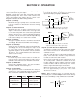
Starter Solenoid Connection Use Only One, 1 amp max Use Continuous Duty Solenoid Pickup Signal Source Connection Use Only One To Batt. + A88-F Mini Auto Starter Remote Annunciator Connection 1 amp max To Batt. + To Batt. + To Batt. + N S 1 2 3 To Starter To Starter Magnetic Pickup Fly Wheel ALT.
Terminal 21: Common Terminal 22: Normally Closed (N.C.) Terminal 23: Normally Open (N.O.
Customer Hookup for Honda Generator Model EM3500SX/EM5000SX Starter * Slave Relay 1 Amp Max Blue Close To Run Open To Stop Grey Charging Coil Float Switch Fuel* Valve 100 1/2 W D1 * R1* * K1 Green IN4005 Yellow Ignition N.O. Battery Pos. Pickup Ground Crank Ignition N.C. Stop Start Oil Press.
Customer Hookup for Honda Generator Model CSX360 * Customer supplied. ** Starter solenoid or 10A 12V relay.