
Data Sheet

Copyright © Murata Manufacturing Co., Ltd. All rights reserved. October 2018
LBAD0ZZ1SE Data Sheet, v1.0, 10/05/2020 Page 4 of 26 www.murata.com
11 ORDERING INFORMATION ........................................................................................................................................ 17
12 NOTICE ........................................................................................................................................................................ 18
12.1 Storage Conditions ................................................................................................................................................... 18
12.2 Handling Conditions ................................................................................................................................................. 18
12.3 Standard PCB Design (Land Pattern and Dimensions) ........................................................................................... 18
12.4 Notice for Chip Placer .............................................................................................................................................. 18
12.5 Operational Environment Conditions ....................................................................................................................... 18
12.6 Input Power Capacity ............................................................................................................................................... 19
13 PRECONDITIONS TO USE MURATA PRODUCTS ................................................................................................... 20
14 REFERENCES ............................................................................................................................................................. 21
LIST OF FIGURES
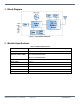
Figure 1 Type 1SE Block Diagram .......................................................................................................................................... 0
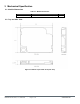
Figure 3.1 Module Top and Side View (Unit: mm) .................................................................................................................. 1
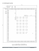
Figure 3.2 Module Footprint Top View (Unit: mm) .................................................................................................................. 2
Figure 8.1 Reflow Profile ......................................................................................................................................................... 8
Figure 9.1 Tape Dimensions (Unit in mm) .............................................................................................................................. 9
Figure 9.2 Reel Dimensions (Unit: mm) .................................................................................................................................. 9
Figure 9.3 Tape Diagram ...................................................................................................................................................... 10
Figure 9.4 Tape Leader and Tail ........................................................................................................................................... 11
Figure 9.5 Peeling Force Diagram ........................................................................................................................................ 12
Figure 9.6 Packaging Diagram.............................................................................................................................................. 12
Figure 9.7 Module Marking Diagram ..................................................................................................................................... 13
LIST OF TABLES
Table 2-1 Module Specifications ............................................................................................................................................. 0
Table 3-1: Module Dimensions ............................................................................................................................................... 1
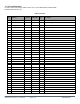
Table 3-2 Pinouts .................................................................................................................................................................... 3
Table 4-1 Rx Sensitivity .......................................................................................................................................................... 6
Table 5-1 Absolute Maximum Rating ...................................................................................................................................... 6
Table 5-2 Recommended Operating Condition ...................................................................................................................... 6
Table 5-3 Temperature Range ................................................................................................................................................ 6
Table 10-1 FCC Test Data .................................................................................................................................................... 14
Table 10-2 ISED Test Data ................................................................................................................................................... 15
Table 11-1 Ordering Information ........................................................................................................................................... 17