MUND CLIMA ® Series 2000 Multisplit 2x1 COOL ONLY: MUP-07X2CN MUP-09X2CN MUP-12X2CN MUP-12+9CN HEAT PUMP: MUP-07X2HN MUP-09X2HN MUP-12X2HN MUP-12+9HN User's manual
The instructions before use WARNING Electric wiring must be installed according to relevant electrical safety rules and regulations. Don’t damage the power cord or use an extended cord. It can cause electric shock or fire. Don’t operate the unit with wet hands. It can cause electric shock. Don’t insert your hands or something else into the air intake or outlet vents. It can cause danger. Don’t apply the cold wind to the body for a longtime.
Don’t use fuse excluding the fuse of correct capacity. Improper wire could cause the break down or fire. Be sure to shut down power supply if not using the Air Conditioner for a longtime. Don’t place a space heater near the unit. Air flow from the outlet can cause incomplete combustion. Keep combustible spray away from the units. It is likely to ignite. Please note whether the installed stand is firm enough or not. It leads to the fall of the unit causes the injury etc. occasionally.
NAME AND FUNCTION OF EACH PART Indoor unit Outdoor unit – 3 –¡ª
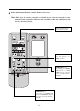
Remote control operation procedure Name and Function-Remote control Note: • Be sure that there are no obstructions. • The remote control signal can be received at a distance of up to about 10m. • Don’t drop or throw the remote control. • Don’t place the remote control in a location exposed to direct sunlight. SWING button FAN button When it is pressed, the louvers start to rotate automatically and stop when repressed. Press this button to change the fan speed of: TEMP.button SET TEMP.
Name and Function-Remote control. (Remove the cover) Note: This type of remote controller is a kind of new current controller. some buttons of the controller which are not available to this Air conditioner will not be described below. Liquid crystal displayer. It shows all set contents. SLEEP button Press this button to set SLEEP operation. TIMER OFF button At operating, press TIMER OFF button, set OFF TIME in range of 0 to 24 hour to stop the unit automatically.
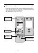
COOL mode operation procedure • According to difference between room temp. and set temp., microcomputer can control cooling on or not. • If room temp. is higher than set temp., compressor runs at COOL mode. • If room temp. is lower than set temp., compressor stops and only indoor fan motor runs. • SET TEMP. should be in range of 16°C to 30°C. 4.Press FAN button, set fan speed. 3.Press SWING button, the louvers start to rotate automatically, and stop when repress. 5.Press TEMP.
HEAT mode operation procedure • If room temp. is lower than set temp., compressor runs at HEAT mode; • If room temp. is higher than set temp., compressor and outdoor fan mortor stop, only indoor fan motor runs. • SET TEMP. should be in range of 16°C to 30°C. 3.Press SWING button, the louvers start to rotate automatically, and stop when repress it. 4.Press FAN button, set fan speed. 5.Press TEMP button, set suitable SET TEMP. 1.Plug in, press 1/0 button,then air conditioner is turned on. 2.
DRY mode operation procedure • If room temp. is lower than set temp., compressor, outdoor and indoor fan mortor stop. If room temp. is between ±2°C of set temp., air conditioner is drying. If room temp. is higher than set temp., it’s at COOL mode. • SET TEMP. should be in range of 16°C to 30°C. 3.Press SWING button, the louvers start to rotate automatically, and stop when repress it. 4.Press TEMP. button, set suitable SET TEMP. 2.Press MODE button, set operation mode. 1.
AUTO mode operation procedure • At AUTO mode operation, standard SET TEMP. is 25°C for COOL mode and 20°C for HEAT mode. 1.Plug in,Press 1/0 button, then air conditioner is turned on. 2.According to room temp. microcomputer can automatically set operation or , mode, so as for best effect.
TIMER mode operation procedure At stopping, press TIMER ON button, set ON TIME in range of 0 to 24 hour to start the unit automatically. At operating,press TIMER OFF button.set OFF TIME in range of 0 to 24 hour to stop the unit automatically.
SLEEP mode operation procedure • When the unit is cooling or drying, if SLEEP operation is set, SET TEMP. would increase 1°C in 1 hour and 2°C in 2 hour. Indoor fan motor runs at low speed. • When the unit is heating , if SLEEP operation is set, SET TEMP. would decrease 1°C, in 1 hour and 2°C in 2 hours. Indoor fan motor runs at low speed. 4.Press FAN button, set fan speed. 3.Press SWING button, the louvers start to rotate automatically, and stop when repress. 6.
How to install batteries 1. Remove the cover from the back of the remote control. 2. Insert the two batteries ( Two AAA dry - cell batteries ) and press button “ACL”. 3. Re - attach the cover. NOTE: • Don’t confuse the new and worn or different batteries. • Remove batteries when not in use for a longtime. • The remote control signal can be received at a distance of up to about 10m.
USER NOTICES Select the most appropriate temperature. It can The air flow direction can be adjusted appro- preclude the electricity wasted. priately. The louvers can be adjusted downward at heating operation, and upward at cooling operation. Don’t leave windows and doors open while operating the air conditioner for a longtime. It can decrease the air conditioning capacity. Don’t blow the wind to animals and plants directly. It can cause a bad influence to them.
Care and Maintenance CAUTION Turn power off and pull out the power plug before cleaning air conditioner. Don’t sprinkle water on the indoor unit and the outdoor unit for cleaning. Wipe the units with a dry soft cloth, or a cloth slightly moistened with water or cleaner. Cleaning surface panel 1. Pull along the direction of arrows to take down surface panel. 2. Washing Wipe with a cloth slightly moistened with water or cleaner, and then dry it in the shade.
3.Reinsert the filters Reinsert the filters with side marked “FRONT” facing forward. Installation of Air cleaner (Refer to the first step of “cleaning the Air Filters”) 1. Remove the Air Filters 2. Install the Air cleaner. Take off the packed bags of Air cleaners, and then put them into the filter frames. Air cleaner NOTE: Be careful not to injure yourself on the fins (Refer to the third step of “cleaning the Air filters”) 3. Reinsert the filters. Preparation before use 1.
Troubleshooting Check the following before requesting on service center if the malfunction occurs. Phenomenon Trouble Shooting Indoor unit does not operate immediately when the air conditioner is restarted. Once the air conditioner is stopped, it will not operate in approximately 3 minutes to protect itself. There’s unusual smell blowing from the outlet after operation is started. This is caused by the odors in the room which have been breathed into the air conditioner.
Immediately stop all operations and plug out, contact with service center of MUNDOCLIMA in following situations. Unusual noise can be heard during operation. Power fuse or switch often breaks. Carelessly splash water or something into air conditioner. Electrical lines and power plug are very hot. Wind blowing from the outlet smells terrible during operation.
Model MUP-07X2CN Functions Cool MUP-07X2HN MUP-09X2CN MUP-09X2HN MUP-12X2CN MUP-12X2HN Cool Heat Cool Cool Heat Cool Cool Heat Accessory Air cleaner Cooling capacity (W) 2000 x 2 2000 x 2 2500 x 2 2500 x 2 3500 x 2 3500 x 2 Heating capacity (W) – 2300x2 – 2800x2 – 3800x2 1150x2/1200x2 1650 x 2 / - 1650 x 2 / 1 5 0 0 x 2 220-230V~50Hz Power supply Input Power (W) 1150 x 2 / - 950x2/950x2 950 x 2 / 3 Air Flow Volume (m /h) 2x420 Refrigerant –18 – Noise (Indoor/Outdoor
Accessories and Installation diagram Accessories (Check that all accessory parts are present before installation) No. Part name Diagram Qty specification 1 Rear panel 2 2 Wireless remote controller 2 3 Battery 2 4 Power connection cord 2 5 Control cord 2 5x1.0 Heat pump type only 6 Tapping screw 2 ST4.
Installation dimension diagram * The installation method of indoor units will be shown by one unit (A unit), that of the other unit (B unit) is the same unless special statement. IMPORTANT NOTES * The installation must be done by trained and qualified service personnel with reliability according to this manual. * Contact with service center of MUNDOCLIMA before installation to avoid the mal-function due to unprofessional installation.
Installation location Indoor unit 1. The inlet and outlet should not be covered so that the outflow air can reach all parts of the room. 2. Install in a location where is permitting easy connection with the outdoor unit. 3. A location from which the condensation water can be drained out conveniently. 4. Avoid a location where there is heat source, high humidity or inflammable gas. 5. Install in a location where is strong enough to withstand the full weight and vibration of the unit. 6.
Install the indoor unit Install the rear panel 1.Always mount the rear panel horizontally. 2.Fix the rear panel on the selected location with screws supplied with the unit. 3.Be sure that the rear panel has been fixed firmly enough to withstand the weight of an adult of 60kg, furthermore, the weight should be evenly shared by each screw. Install the drain hose 1.For well draining, the drain hose should be placed at a downward slant. 2.Do not wrench or bend the drain hose or flood its end by water.
NOTE: All the electrical work must be done by qualified personnel according to national wiring regulation and this manual. The power supply is type Y connection. If the supply cord is damaged, it must be replaced by the manufacturer or its service agent or a similarly qualified person in order to avoid a hazard. The rated voltage and the exclusive circuit must be used. Leakage circuit - breaker and air switch of correct capacity must be installed.
Install the outdoor unit Install the connection pipe 1. Align the center of the piping lare with the relevant valve. 2. Screw in the flare nut by hand and then tighten the nut with spanner and torque wrench. Note: Exceeding tightening torque will damage the flare surface. Tightening torque table Hex nut diameter (mm) Tightening torque (N.m) Ø6 15 – 20 Ø9.5 31 – 35 Ø12 50 – 55 Electric wiring connection 1. Disassemble the front-side plate. 2.
Air purging and leakage test 1.Remove the flare nuts from the cut-off valves of the outdoor unit. 2.Align the center of the piping flare with the relevant valve, and screw in the flare nut about 3 – 4 turns by hand. 3.Tighten the flare nut with spanner and torque wrench. 4.Remove the valve caps of the gas valve and liquid valve and the service port nut. 5.Loosen the valve stem of the liquid valve with a hex wrench. 6.
Test operation and check after installation Test operation 1. Before test operation (1) Do not switch on power before installation is finished completely. (2) Electric wiring must be connected correctly and securely. (3) Cut-off valves of the connection pipes should be opened. (4) All the impurities such as scraps and thrums must be clear from the unit. (5) Open the surface panel and set the handling switch to “RUN” mode. 2.
Electrical wiring diagram – 28 –¡ª Note: This diagram is just for reference only, the accurate diagram is labeled on the units you bought.
Installation The instructions before use 1 Name and function of each part 3 Remote Control operation procedure Operation and maintenance CONTENT Name and function - Remote control 4 Name and function - Remote control (Remove the cover) 5 COOL mode operation procedure 6 HEAT mode operation procedure 7 DRY mode operation procedure 8 AUTO mode operation procedure 9 TIMER mode operation procedure 10 SLEEP mode operation procedure 11 How to install batteries 12 User notices 13 Care an