
User Manual


Other Neat Stuff
LCD Configuration
It is possible to attach an LCD panel for field adjustment of PID values without
the need for a PC. Stick movements are used to change values, while the LCD
shows the variable being changed and by how much.
Search Ebay for “Multiwii LCD” to obtain one
Installation: just plug it into the TTL output pins beside the FTDI connector…be
sure that you get power and gnd correctly oriented!
Operation: see the LCD section of this page:
http://www.multiwii.com/software
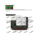
Bluetooth Configuration
Another option for field configuration without a PC is to use an Android
smartphone and a Bluetooth module. The module connects to the TTL port pins
as the LCD does, but uses all four pins since the communication is bi-directional
in this case with the board.
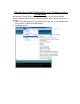
The application is free. Here is a link to the app and sources for appropriate
modules:
http://www.androidpit.com/en/android/market/apps/app/net.xrotor.andmultiwiiconf/Andr
oid-MultiWii-Configuration
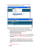
Note that after you add this module, if you get a USB Bluetooth dongle for your
PC you can remove the FTDI module since you can communicate with the PC
over Bluetooth now instead of USB for code updates, configuration, etc.
Note: You cannot have both the BT module and FTDI active at the same time.
Use one or the other at a time. You do not use the #BTSERIAL define! This
define is for remote control of the copter using BT instead of a RC transmitter
and uses a different phone app!
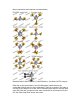
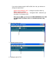
Using RC receivers with a PPM composite output
Some RC receivers (like the FrSky and some Hitec) have an output in which all
the channels are output in a single stream. This allows you to use only one servo
wire connection between the RX and the MultiWii, eliminating all other
connectons and cutting down on wiring mess. Attach it to the first RX input pin on
the board, THROTTLE.