
Installation Guide

9261-8252 Issue 07
Description
Page 8
www.multitone.com
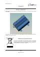
The transmitter requires 13.8VDC at about 2.1A. The DC input to the transmitter is via a 2.1mm
connector. To fit the locking type connector to the transmitter, push the connector in and turn it until
the two locking lugs enter the socket and none of the connector barrel is visible. Then turn the
connector a quarter turn clockwise.
To disconnect, first turn the connector a quarter turn anti-clockwise and then pull.
4.3 AERIAL (see also 2.3)
The impedance of the aerial should be 50 ohms. It is recommended that the aerial be connected to the
transmitter by coaxial cable and be sited at least 1.5 metres from the transmitter.
Care must be taken during installation to keep the power supply away from
excessive RF fields.
Where the transmitter power is to be greater than 2.5W, the antenna must be sited a minimum
of 1.5
metres away from the RPE/RPT500 housing and power supply.
In cases where a close-coupled antenna must be used, the transmitter power must be reduced to a
maximum
of 2.5W and care must be taken to position the antenna at least 0.5m from the power
supply unit.
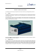
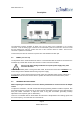
4.4 TRANSMITTER ADJUSTMENT
Whilst adjusting the transmitter, an aerial or dummy load MUST be connected to the RF Output
socket.
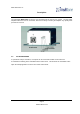
To adjust the transmitter, a PC with the RPT500 field programming software installed is required, with
the RS232 serial port connected to the 15 way hi-density D Auxiliary Connector on the RPT500 using
lead part number 7761-8251. To adjust the VCO, a long thin non-metallic (preferably ceramic)
adjustment tool is required (part no. 8902-0004.)
There are no selectable links or diodes within the transmitter. All adjustments and settings, apart from
the VCO frequency, are made from the connected PC.