
Installation Guide

9261-8252 Issue 07
Description
Page 18
www.multitone.com
SECTION 5 - RPT500 DISASSEMBLY and REASSEMBLY
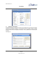
5.1 DISASSEMBLY
Ensure that the transmitter is unplugged.
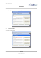
Remove the 3 x M3 screws from either side of the transmitter.
Remove the four front retaining screws.
Pull the transmitter circuit board out of the case from the front, with the front panel attached.
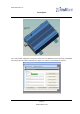
5.2 REASSEMBLY
Slide the transmitter into the correct runners, so that the front panel aligns with the case. Ensure that
the rear connectors align with their cut-outs. This does not require undue force!
Loosely fit the M3 screws in the side of the transmitter.
Fit the four front retaining screws and tighten
Tighten the M3 screws fully to pull the power amplifier heat-sink into close contact with the case.