
Installation Guide

9261-8252 Issue 07
Description
Page 17
www.multitone.com
4.11 CONNECTIONS
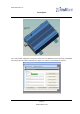
RF output is via the N-type connector on the front of the transmitter.
The line connector is an 8-pin RJ45 socket. This connector carries both the Audio Line and the Line
Synchronisation circuits. The Audio/Data Line connections are compatible with the P251 Series.
Input is 600 Ohms impedance and should be at –13dBm level.
Pins 2 and 4 are Audio/Data Line, Pins 6 and 8 are Line Synchronisation line (also –13dBm 600
Ohms.)
Direct inputs (Data, Key and Mode) are on the Auxiliary Connector. Cable 7761-8245 is available,
which has the connector on one end and open wires at the other, for connection in a junction box.
4.11.1 Auxiliary Connections:
Pin Wire colour Function
1 Flash Input – Do not connect
2 Black Ground
3 Yellow Ground
4 Green Ground
5 Orange Ground
6 Pink Data Input
7 Flash Input – Do not connect
8 Grey Mode Line Input
9 Flash Input – Do not connect
10 Blue Key Line Input
11 Red Fault Output (open collector)
12 Violet 12V 10mA Output
13 Brown Serial RS232 Transmit Data
14 Pink Serial RS232 Receive Data
15 Flash Input – Do not connect
Turquoise Cut Short
The polarity for the mode, key and data lines, is software selectable from the field programmer.
The Serial RS232 circuits on this socket, are for connection to the field programmer.
The Flash Inputs are for re-flashing the RPT500 firmware. These must not be connected!