Dual Ethernet ProxyServer Model MTPSR1-120 User Guide
User Guide 88301501 Revision B Dual Ethernet ProxyServer (Model No MTPSR1-120) This publication may not be reproduced, in whole or in part, without prior expressed written permission from Multi-Tech Systems, Inc. All rights reserved. Copyright © 1999, by Multi-Tech Systems, Inc. Multi-Tech Systems, Inc. makes no representations or warranties with respect to the contents hereof and specifically disclaims any implied warranties of merchantability or fitness for any particular purpose.
Contents Chapter 1 - Introduction and Description Introduction ................................................................................................................................................ 6 Preview of this Guide ................................................................................................................................. 6 Front Panel Description ............................................................................................................................
Chapter 5 - Remote Configuration and Management Introduction .............................................................................................................................................. Remote Configuration .............................................................................................................................. Modem-Based ................................................................................................................................... LAN-Based ......
Chapter 1 - Introduction and Description
Firewall User Guide Introduction Welcome to Multi-Tech's Dual Ethernet ProxyServer, model number MTPSR1-120 (hereafter, Firewall) a high speed Internet access device that provides firewall protection to your corporate secured (private) LAN and allows Internet access to the Internet Services Network (public LAN) that resides outside the firewall.
Chapter 1 - Introduction and Description Chapter 4 - Firewall Software Chapter 4 describes the Firewall software package designed for the Windows ® environment. This chapter describes the Firewall software from an applications standpoint, and in so doing, not every screen is shown, nor is each field within a screen defined. For explanations and parameters of each field within a dialog box please refer to the online Help provided within the software.
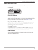
Firewall User Guide Front Panel Description The front panel, shown in Figure 1-2, contains four groups of LEDs that provide the status of the LAN connection, link activity, and general status of the Firewall. The Ethernet 1 and Ethernet 2 LEDs display the activity of the public and private LANs, in whether the Firewall is connected to the LAN, transmitting or receiving packets, and if a collision is in progress. The WAN Link LEDs display the status of the RS232/V.
Chapter 1 - Introduction and Description Back Panel Description The cable connections for the Firewall are made at the back panel. In addition to the Power connector, Three groups of connectors are used on the Firewall: the Command Port, Ethernet 1 & 2 (10BASET) and RS232/V.35. The cable connections are shown in Figure 1-3 and defined in the following groups. RS232/V.35 ETHERNET 2 1 COMMAND POWER ON OFF 10BASET 10BASET Figure 1-3. Back Panel RS232/V.35 Connector The RS232/V.
Firewall User Guide Specifications • Protocols - Point-To-Point Protocol (PPP), and Serial Line Internet Protocol (SLIP) Ethernet Ports • Two Ethernet Interface - 10Base-T (twisted pair) RJ-45 connectors. Command Port • Single 19.2K bps asynchronous Command Port using a short RJ-45 to DB-25 cable with a DB-25 female connector WAN Link • One RS232/V.35 port connector.
Chapter 2 - Installation
Firewall User Guide Safety Warnings 1. Never install telephone wiring during a lightning storm. 2. Never install telephone jacks in wet locations unless the jack is specifically designed for wet locations. 3. Never touch uninsulated telephone wires or terminals unless the telephone line has been disconnected at the network interface. 4. Use caution when installing or modifying telephone lines. 5. Avoid using a telephone (other than a cordless type) during an electrical storm.
Chapter 2 - Installation V.35 Shunt Procedure If you are using an external DCE device on the WAN RS232/V.35 port, and the connection will be a V.35 connection, the internal shunt must be moved from the RS232C (default) position prior to cabling and power-up. The following steps detail the procedures for switching the shunt. Step Procedure 1 Ensure that the external power supply is disconnected from the Firewall. 2 Turn the Firewall over and remove the cabinet mounting screw from the chassis.
Firewall User Guide Cabling Your Firewall Cabling your Firewall involves making the proper Power, Command Port, and Ethernet connections. An optional WAN connection is provided to connect to an external WAN device. Figure 2-4 shows the back panel connectors and the associated cable connections, and the table that follows details the procedures for connecting the cables to your Firewall. ETHERNET RS232/V.
Chapter 2 - Installation 6. Turn on power to the Firewall by placing the ON/OFF switch on the back panel to the ON position. Wait for the Fail LED on the Firewall to go OFF before proceeding. This may take a couple of minutes to go OFF. At this time your Firewall is completely cabled. Proceed to Chapter 3 to load the Firewall software.
Firewall User Guide 16
Chapter 3 - Software Loading and Configuration
Firewall User Guide Loading Your Software The following loading procedure does not provide every screen or option in the process of installing the Firewall software. The assumption is that the installation is being performed by a technical person with a thorough knowledge of Windows and the software loading process. Additional information on the Firewall software is provided in the Chapter 4, and in the on-line help provided with your Firewall software. 1.
Chapter 3 - Software Loading and Configuration The Select Program Folder dialog box enables you to use the default or select a different name for the new program group for the Firewall 2.00 software. After accepting the default or selecting a different folder name, press Enter or click Next > to continue. 6. The next dialog box enables you to designate the COM port of your PC that is connected to the Firewall.
Firewall User Guide Wizard Setup The Wizard Setup screen gives you a process for adding the basic information needed to configure your Firewall. This screen will guide you through entering the IP Address, Net Mask, and Default Route for your Secure (private) LAN. Then you can set up for static or dynamic addressing on the Internet LAN Port, set up the Gateway Parameters, and then do the same for the WAN port, if it is used. 9. Click Yes to run the Wizard Setup.
Chapter 3 - Software Loading and Configuration Internet LAN (LAN 2) Setup WAN Setup 12. If a WAN device is connected to the WAN Port (marked RS-232/V.35), click the WAN option in the Select Port window, then either leave the “ISP Assigned Dynamic IP Address & Mask” option enabled or disable (uncheck) it and assign the proper IP Address and Net Mask for your WAN port.
Firewall User Guide Default WAN Link Configuration The Default WAN Link(s) Setup dialog box is used only if a device is connected to the RS-232/ V.35 connector on the back panel of the Firewall. This connection enables your Secure (private) LAN to be connected to a local ISP for Internet service. However, if you are using the LAN 2 port, then you will have to disable the RS-232/V.35 WAN port on this dialog box. 14.
Chapter 3 - Software Loading and Configuration 21. Check to ensure that the Fail LED on the Firewall is Off after the download is complete and the Firewall is rebooted. 22. Win3.1 users - you are returned to your Program Manager where the Firewall 2.00 Program Group and Program Items (Windows icons) have been created. Win95/NT users - you are returned to the Firewall 2.00 folder which will be open and visible on your desktop.
Firewall User Guide 24
Chapter 4 - Firewall Software
Firewall User Guide Introduction This chapter describes the software used in the Firewall. It begins with the description of three typical applications for the Firewall. These configuration examples are followed by a description of the Firewall program group, and examples of how to add some of the advanced features provided with the software. Typical Applications This section describes three typical applications for the Firewall.
Chapter 4 - Firewall Software During the loading of the Firewall software, the Secured LAN Port Parameters group (in the IP Setup dialog box) was configured to include an unregistered IP Address of 192.168.0.101 and default Net Mask of 255.255.255.0 for the Secured (private) LAN. The Internet LAN Port Parameters group was configured with the DHCP Client option active. This enables the Internet Services Provider (ISP) to dynamically provide the registered Internet IP addresses.
Firewall User Guide During the loading of the Firewall software, the Secured LAN Port Parameters group (in the IP Setup dialog box) was configured to include an IP Address of 192.168.0.101, and a default Net Mask of 255.255.2.55.0 for the Secured (private) LAN. The Internet LAN Port Parameters group was configured with the DHCP Client option disabled, and the static IP Address of 204.26.12.10 was entered.
Chapter 4 - Firewall Software In the configuration shown in Figure 4-3, the Firewall is connected to the Secured (private) LAN via the LAN 1 connection of the back of the unit. The Internet (public) LAN is connected to the LAN 2 connector on the back of the unit. Connection to the Internet is then provided by a T1 DSU connected to the RS232/V.35 connector on the back of the unit.
Firewall User Guide Firewall Program Group This section describes the advanced features of your Firewall software. The major configuration parameters are set when the software is loaded into your PC and the setup configuration is downloaded to the Firewall at the conclusion of the software installation. Our intent is not to cover every dialog box nor every field within a dialog box.
Chapter 4 - Firewall Software Configuration Port Setup The Configuration Port Setup program allows you to set up and configure the configuration port on your Firewall. This dialog is included in the initial installation process. Although parameters can be changed, be sure to note the current status of the software before making any alterations. When you installed the Firewall software, you selected to configure the port as either an IP or COM Port.
Firewall User Guide Firewall Configuration To view or change your Firewall configuration in Windows 95/98/NT, click on the Start | Programs | Firewall | Firewall Configuration. After loading, the Firewall Setup menu will appear.
Chapter 4 - Firewall Software Changing IP Parameters The IP Setup dialog box establishes the IP addressing for your Secured (private) LAN, Internet (public) LAN, and, if the Firewall is directly connected to the Internet via the RS-232/V.35 connector, the WAN port. To change the IP Setup parameters that were configured during the Wizard Setup, click on the IP button in the Firewall Setup menu. The IP Setup dialog is displayed.
Firewall User Guide DHCP Relay Agent - Enabling this option allows the Firewall to relay IP address requests from the Internet to the DHCP server through the WAN. If this option is enabled, the DHCP Server Address field becomes active, and the IP address of the DHCP server must be entered. DHCP Server Address - If the DHCP Relay Agent option is active, enter the IP address of the DHCP server in this field. The WAN Port Parameters group is used to configure the WAN port, if enabled.
Chapter 4 - Firewall Software Changing WAN Port Parameters In order to change the WAN port parameters of a DCE device connected to the RS232/V.35 connector on the Firewall, click on the WAN button in the Firewall Setup menu. The WAN Port Setup dialog box is displayed. From this dialog, you can configure the parameters of the WAN port. To enable the WAN port, click on the Port Enable check box. The Mode group allows you to configure the WAN interface to match the DCE device connected to the RS232/V.
Firewall User Guide Enabling PPP/SLIP If you wish to use Point to Point Protocol (PPP) or Serial Line IP Protocol (SLIP) on the WAN port, you can enable it in the PPP/SLIP menu. In order to configure these options, you must first enable the WAN port. To enable the WAN port, click on the WAN button in the Firewall Setup menu. The WAN Setup dialog box appears. Click on the Port Enable check box enable the WAN port. Click OK. You are returned to the Firewall Setup menu. Click on PPP/SLIP.
Chapter 4 - Firewall Software Enabling SLIP If you wish to configure the port for use with SLIP, click on the Enable check box in the SLIP group. The following message appears: Click OK. This value was assigned in the initial software installation and was downloaded to the ProxyServer at the end of the installation. If you wish to verify or change the WAN IP address, click on IP in the Firewall Setup menu.
Firewall User Guide Enabling the DHCP Server The DHCP Server feature of the Firewall manages all the IP address assignments on the Secured (private) LAN port. IP address management becomes completely transparent. To enable the DHCP Server ability in the Firewall, click on the DHCP Server button in the Firewall Setup menu. The DHCP Server Setup dialog box appears. The DHCP Server Setup menu allows you to customize each client PC configuration from one central point.
Chapter 4 - Firewall Software Adding Proxy Applications Certain software on your LAN may require a TCP or UDP port usage that is not currently supported by the Firewall. If this is the case, you must refer to the software documentation to determine the proper port usage and number. Without this information, the Firewall will not allow packets through to the Internet from the unknown software. Once the necessary information has been determined, you can add the application(s) to the supported list.
Firewall User Guide Filtering The Filters dialog lets you configure the Firewall so that IP packets that are received by the server can be selectively filtered or forwarded based on their addresses or by the protocol ports to which they are destined. The five filtering methods are: • Internet Sites (IP Address) - In this method, IP packets can be filtered based on the IP address of an Internet Site. To add a new filter, enter the proper IP address in the Destination IP Address field and click Add.
Chapter 4 - Firewall Software Enabling Virtual Servers The Virtual Server Setup dialog box allows you to assign a virtual address to a statically assigned server. For example, if the ISP assigns static address of 200.2.9.1, you can set up a virtual server so that any requests sent to 200.2.9.1 will access 192.168.0.102. Click on the Virtual Servers button in the Firewall Setup menu. The Virtual Server Setup dialog box appears. To add a Virtual Server, type a valid IP address (200.2.9.
Firewall User Guide Statistics The Firewall is capable of providing statistics for the WAN port and for the whole system. These statistics can be useful for troubleshooting and management purposes. To access this information, click Statistics in the Firewall Setup menu. The Statistics dialog box is displayed. From this menu, you can query the details of the WAN port or observe total system statistics such as total system Uptime, and total Calls.
Chapter 5 - Remote Configuration and Management
Firewall User Guide Introduction This chapter provides procedures for viewing or changing the configuration of a remote Firewall unit. Two methods are provided to access a remote unit; the first method is modem-based and the second method uses IP. Within the IP method, three applications can be used: 1) LAN-based using Trivial File Transfer Protocol (TFTP), 2) Telnet as a client application, and 3) a standard Web browser on the Internet.
Chapter 5 - Remote Configuration and Management 5 The Firewall Setup dialog box is displayed. Verify that the Communication Type is set for COM Port and the Select Port field is set for the COM port of your local PC. In the Dial String field, enter the AT command for dialing (ATDT) plus the phone number of the remote ProxyServer.
Firewall User Guide LAN-Based The LAN-based remote configuration requires a Windows Sockets compliant TCP/IP stack. TCP/ IP protocol software must be installed and functional before the configuration program can be used. Local Workstation TFTP, Telnet or Web Browser Remote Firewall Internet Figure 5-2. LAN-Based Remote Configuration 1 You must assign an Internet (IP) address for the PC and for each node that will be managed by the configuration program.
Chapter 5 - Remote Configuration and Management 7 After you have changed the configuration of the remote Firewall, click Download Setup to update the configuration. The remote Firewall will be brought down, the new configuration written to the unit, and the unit will reboot. 8 Click Exit when the downloading is complete. 9 Double click on the Firewall Configuration icon in the Firewall program group to verify that the ProxyServer is running.
Firewall User Guide Remote Management This section describes typical client applications that can be used to configure the ProxyServer remotely. It is important to note that although any subsequent changes to configuration can be made using these applications, the initial setup and configuration of the ProxyServer must be done on the local PC, using the ProxyServer software provided with your unit.
Chapter 5 - Remote Configuration and Management Firewall Management Menu The Firewall Management Menu provides two basic options: Firewall Configuration and WAN Device Configuration. A further option enables you to close the Telnet session from this menu by pressing the Esc key. Firewall Management Selecting Option 1 displays the Firewall Management menu with options that allow you to view statistics for IP, TCP, ARP, RARP, ICMP, UDP, WAN and PPP. In addition, you can access system information.
Firewall User Guide WEB Management The ProxyServer can be accessed, via a standard web-browser, from anywhere on the connected Internet. In order to provide this support, the WEB Server option has to be enabled in the Applications Setup dialog box (see Chapter 4 - Firewall Software, Applications). Once enabled, users can access the ProxyServer by entering its IP address in the destination field of their web browser. The following screen appears.
Chapter 6 - Warranty, Service and Tech Support
Firewall User Guide Introduction This chapter starts out with statements about your Dual Ethernet ProxyServer 2-year warranty. The next section, Tech Support, should be read carefully if you have questions or problems with your ProxyServer. It includes the technical support telephone numbers, space for recording your product information, and an explanation of how to send in your ProxyServer should you require service.
Chapter 6 - Warranty, Service and Technical Support Tech Support Multi-Tech has an excellent staff of technical support personnel available to help you get the most out of your Multi-Tech product. If you have any questions about the operation of this unit, call 1800-972-2439. Please fill out the ProxyServer information (below), and have it available when you call. If your ProxyServer requires service, the tech support specialist will guide you on how to send in your ProxyServer (refer to the next section).
Firewall User Guide Service If your tech support specialist decides that service is required, your ProxyServer may be sent (freight prepaid) to our factory. Return shipping charges will be paid by Multi-Tech Systems. Include the following with your ProxyServer: • a description of the problem. • return billing and return shipping addresses. • contact name and phone number. • check or purchase order number for payment if the ProxyServer is out of warranty.
Chapter 6 - Warranty, Service and Technical Support The Multi-Tech BBS For customers who do not have Internet access, Multi-Tech maintains a bulletin board system (BBS). Information available from the BBS includes new product information, product upgrade files, and problem-solving tips. The phone number for the Multi-Tech BBS is (800) 392-2432 (USA and Canada) or (612) 785-3702 (international and local).
Firewall User Guide 5. Enter D. You will see a list of the files you have marked. Enter E if you would like to edit the list; otherwise enter D again to start the download process. 6. Select a file transfer protocol by typing the indicated letter, such as Z for Zmodem (the recommended protocol). 7. If you select Zmodem, the file will transfer automatically. If you select another protocol, you may have to initiate the transfer yourself.
Appendixes
Firewall User Guide Appendix A - TCP/IP (Transmission Control Protocol/ Internet Protocol) Description TCP/IP is a protocol suite and related applications developed for the U.S. Department of Defense in the 1970s and 1980s specifically to permit different types of computers to communicate and exchange information with one another. TCP/IP is currently mandated as an official U.S. Department of Defense protocol and is also widely used in the UNIX community.
Appendix A - TCP/IP Description UDP, described in RFC 768 (http://info.internet.isi.edu:80/in-notes/rfc/files/rfc768.txt) provides an end-to-end datagram (connectionless) service. Some applications, such as those that involve a simple query and response, are better suited to the datagram service of UDP because there is no time lost to virtual circuit establishment and termination. UDP’s primary function is to add a port number to the IP address to provide a socket for the application.
Firewall User Guide Internet Protocol (IP) IP is the Internet standard protocol that tracks Internetwork node addresses, routes outgoing messages and recognizes incoming messages, allowing a message to cross multiple networks on the way to its final destination. The IPv6 Control Protocol (IPV6CP) is responsible for configuring, enabling, and disabling the IPv6 protocol modules on both ends of the point-to-point link. IPV6CP uses the same packet exchange mechanism as the Link Control Protocol (LCP).
Appendix B - Cabling Diagrams Appendix B - Cabling Diagrams WAN Port Cable (RS-232/V.
Firewall User Guide DB-25 (RS-232) to V.35 Adapter V.
Appendix C - Regulatory Information Appendix C - Regulatory Information FCC Declaration NOTE: This equipment has been tested and found to comply with the limits for a Class A digital device, pursuant to Part 15 of the FCC Rules. These limits are designed to provide reasonable protection against harmful interference when the equipment is operated in a residential installation.
Firewall User Guide 64
Glossary
Firewall User Guide A Access: The T1 line element made up of two pairs of wire that the telephone company brings to the customer premises. The Access portion ends with a connection at the local telco (LEC or RBOC). Accunet Spectrum of Digital Services (ASDS): The AT&T 56K bps leased (private) line service. Similar to services of MCI and Sprint. ASDS is available in nx56/64K bps, where n=1, 2, 4, 6, 8, 12.
Glossary Basic Rate Interface (BRI): An ISDN access interface type comprised of two B-channels each at 64K bps and one Dchannel at 64K bps (2B+D). Bell Operating Companies (BOC): The family of corporations created during the divestiture of AT&T. BOCs are independent companies which service a specific region of the US. Also called Regional Bell Operating Companies (RBOCs).
Firewall User Guide Centrex: A multi-line service offered by operating telcos which provides, from the telco CO, functions and features comparable to those of a PBX for large business users. See also “Private Branch Exchange”, “Exchange”. Channel: A data communications path between two computer devices. Can refer to a physical medium (e.g., UTP or coax), or to a specific carrier frequency.
Glossary Data Link Connection Identifier (DLCI): One of the six components of a frame relay frame. Its purpose is to distinguish separate virtual circuits across each access connection. Data coming into a frame relay node is thus allowed to be sent across the interface to the specified “address”. The DLCI is confirmed and relayed to its destination, or if the specification is in error, the frame is discarded.
Firewall User Guide Encapsulation: A technique used by network-layer protocols in which a layer adds header information to the protocol data unit from the preceding layer. Also used in “enveloping” one protocol inside another for transmission. For example, IP inside IPX. Errored Seconds (ES): Any second of operation that all 1.544M bits are not received exactly as transmitted. Contrast “Error Free Seconds”. Error Free Seconds (EFS): Any second of operation that all 1.
Glossary Foreign Exchange Station (FXS): See FX, FXO. To generate a call from the computer telephony system to the POTS set, an FXS connection must be configured. Forward Explicit Congestion Notification (FECN): A bit that tells you that a certain frame on a particular logical connection has encountered heavy traffic. The bit provides notification that congestion-avoidance procedures should be initiatedin the same direction of the received frame. See also BECN (Backward Explicit Congestion Notification).
Firewall User Guide Internetwork Packet Exchange (IPX): A NetWare communications protocol used to route messages from one node to another. IPX packets include network addresses and can be routed from one network to another. An IPX packet can occasionally get lost when crossing networks, thus IPX does not guarantee delivery of a complete message. Either the application has to provide that control, or NetWare’s SPX protocol must be used.
Glossary Local Exchange Carrier (LEC): The local phone company which provides local (i.e., not long distance) transmission services. AKA “telco”. LECs provide T1 or FT1 access to LDCs (unless the T1 circuit is completely intra-LATA). InterLATA T1 circuits are made up of a combination of Access and Long Haul facilities. Local Management Interface (LMI): A specification for frame relay equipment that defines status information exchange.
Firewall User Guide O Object-Oriented: A method for structuring programs as hierarchically organized classes describing the data and operations of objects that may interact with other objects. Office Channel Unit - Data Port (OCU-DP): The CO channel bank used as the interface between the customer’s DSU and the channel bank. Off-hook: The condition of a device which has accessed a phone line (with or without using the line). In modem use, this is equivalent to a telephone handset being picked up.
Glossary Private Branch Exchange (PBX): A telephone exchange located on the customer’s premises. The PBX provides a circuit switching facility for telephone extension lines within the building, and access to the public telephone network. See also “Exchange”. PROM (Programmable Read Only Memory - pronounced “prom”): A permanent memory chip that can be programmed or filled by the customer after by the manufacturer has set initial values. Contrast with ROM. Protocol: 1.
Firewall User Guide Router: A device that connects two networks using the same networking protocol. It operates at the Network Layer (Layer 3) of the OSI model for forwarding decisions. Routing Information Protocol (RIP): A distance vector-based protocol that provides a measure of distance, or hops, from a transmitting workstation to a receiving workstation. RS232-C: An EIA standard for a serial interface between computers and peripheral devices (modem, mouse, etc.).
Appendix C - Regulatory Information Systems Network Architecture (SNA): The description of the logical structure, formats, protocols, and operational sequences for transmitting information units through, and controlling the configuration and operation of networks. T Tariff: The rate/availability schedule for telephone and ISDN services from a regulated service provider. TCP/IP: A set of communication protocols that support peer-to-peer connectivity functions for both local and wide area networks.
Firewall User Guide Transport Protocol Data Unit (TPDU): A transport header, which is added to every message, contains destination and source addressing information that allows the end-to-end routing of messages in multi-layer NAC networks of high complexity. They are automatically added to messages as they enter the network and can be stripped off before being passed to the host or another device that does not support TPDU’s. Trunk: Transmission links that interconnect switching offices.
Index Index G Gopher ............................................................... 59 A About the Internet ............................................... 56 About the Multi-Tech Fax-Back Service .............. 56 Adding Proxy Applications .................................. 36 Applications ........................................................ 42 Archie ................................................................. 59 B Back Panel ...........................................................
Firewall User Guide Software ............................................................. 26 Applications .................................................... 42 Configuration Port Setup ................................. 31 DHCP Server .................................................. 38 Download Firmware Update ............................ 31 Filtering ........................................................... 40 Firewall Configuration ..................................... 32 IP Parameters ............