
User guide


Chapter 2: Installation & Activation
Multi-Tech Systems, Inc. MVPGSM 11
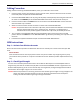
Cabling Procedure
Cabling involves connecting the MultiVOIP GSM to power, your LAN and a serial console.
1. Connect a power cord to the transformer and to a live AC outlet, and then attach the barrel connector
to the back power receptacle of the MultiVOIP GSM.
2. Connect the MultiVOIP GSM to a PC by using a RJ-45 (male) to DE-9 (female) cable. Plug the RJ-45 end of
the cable into the CONSOLE port of the MultiVOIP GSM and the other end into the PC serial port.
3. Connect a network cable to the WAN connector on the back of the MultiVOIP GSM. Connect the other
end of the cable to your network.
4. Attach an antenna to both channel connectors on either side of the MultiVOIP GSM.
Caution: A separation distance of at least 20 cm (8 inches) must be maintained between all transmitting
antennas and the body of the user or nearby persons. This device is not designed for or
intended to be used in portable applications within 20 cm (8 inches) of the body of the user.
5. Turn on power to the MultiVOIP GSM by placing the ON/OFF switch on the back panel to the ON
position. Wait for the BOOT LED on the MultiVOIP GSM to go off before proceeding. This may take a few
moments.
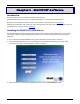
6. Proceed to the Software Installation chapter to load the MultiVOIP GSM software.
GSM Instructions
Step 1 – Activate Your Wireless Accounts
Select a wireless network provider and follow their directions to activate your account and receive your SIM
cards.
Phone Numbers
Each channel will have its own unique phone number. The phone number may simply be given to you by
your wireless service provider or it may be on the SIM card or both. Wireless provider implementations may
vary.
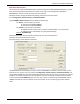
Step 2 – Check Signal Strength
Turn the unit on and verify that the Power LED is lit and that the Boot sequence is finished (Boot LED is no
longer active), then wait for the Link Status (LS) LED to show that the MVPGSM channel is registered on the
wireless network (flashing 75 ms on and 3 seconds off). Once registered, the Signal Strength LEDs should be
referenced for the strength of signal in its current location.
Caution: Before final placement or mounting, ensure that the wireless signal strength is strong enough for the
chosen area. Signal strength information is found in the Front Panel LEDs section of Chapter 1.
Finding a location with the strongest signal strength is desirable.