® MultiVOIP GSM SIP-to-Cellular Gateway Model: MVPGSM-2 User Guide
User Guide S000450C Wireless MultiVOIP GSM Unit (Model: MVPGSM-2) This publication may not be reproduced, in whole or in part, without prior expressed written permission from Multi-Tech Systems, Inc. All rights reserved. Copyright © 2010, by Multi-Tech Systems, Inc. Multi-Tech Systems, Inc. makes no representations or warranty with respect to the contents hereof and specifically disclaims any implied warranties of merchantability or fitness for any particular purpose.
CONTENTS CHAPTER 1 – DESCRIPTION AND SPECIFICATIONS ..................................................................................................... 4 Specifications ........................................................................................................................................................ 7 Unpacking Your MultiVOIP GSM ........................................................................................................................... 8 Safety Warnings ...............
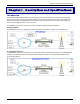
Chapter 1: Description & Specifications Chapter 1 – Description and Specifications Introduction The MultiVOIP GSM provides wireless voice communications over the Internet or an Intranet. By integrating wireless connectivity into your existing data network, you can realize substantial savings on inter-office long distance toll charges. The MVPGSM has “phone books,” which are directories set up to simulate dialing and connecting as though the call was in the local area.
Chapter 1: Description & Specifications As a Survivable SIP Server: In this mode the MVPGSM functions as a Back to Back User Agent (B2BUA) and routes SIP registration and call control packets between the SIP endpoints and Primary proxy. The MVPGSM monitors the status of the primary proxy and, if the primary proxy is unavailable, the MVPGSM functions as a SIP server and takes over the routing of calls between SIP endpoints.
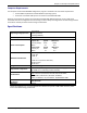
Chapter 1: Description & Specifications Front Panel LEDs The table below describes what the LED indicators represent. Front Panel LED Definitions LED Description Power Indicates presence of power After power up, the Boot LED will be on while the MultiVOIP GSM is booting. It lights whenever the MultiVOIP GSM is booting, saving a configuration or receiving a firmware upgrade. LNK. Link/Activity LED. This LED is lit if Ethernet connection has been made. It is off when the link is down (i.e.
Chapter 1: Description & Specifications Computer Requirements The computer on which the MVPGSM configuration program is installed must meet these requirements: • • must be IBM-compatible PC with MS Windows operating system; must have an available COM port for connection to the MultiVOIP GSM. However, this PC does not need to be connected to the MultiVOIP GSM permanently. It only needs to be connected when local configuration and monitoring are done.
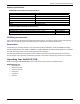
Chapter 1: Description & Specifications Antenna Specifications GSM/EGSM Antenna Requirements/Specifications Frequency Range: Impedance: VSWR: Typical Radiated Gain: Radiation: Polarization: Wave: 824 – 960 MHz / 1710 – 1990 MHz 50 Ohms <2.0:1 3 dBi on azimuth plane Omni Vertical Half Wave Dipole Antennas available from Multi-Tech Systems, Inc. Description 900/1800 MHz 1/2 Wave Antenna Mag Mount, 12.5", 1 Pack 850/1900 MHz 1/2 Wave Antenna Mag Mount, 12.
Chapter 1: Description & Specifications Safety Warnings Lithium Battery Caution A lithium battery on the voice/fax channel board provides backup power for the timekeeping capability. The battery has an estimated life expectancy of ten years. When the battery starts to weaken, the date and time may be incorrect. If the battery fails, the board must be sent back to Multi-Tech Systems for replacement. Warning: There is danger of explosion if the battery is incorrectly replaced.
Chapter 2 – Getting Started Introduction The MultiVOIP GSM is equally usable as tabletop unit or mounted in a location with good reception. The initial setup is best performed before any mounting is done. Installing SIM Cards The MVPGSM requires at least one SIM card (Subscriber Identity Module) to operate on a GSM network. To install the SIM cards, do the following: 1. Turn the unit off and disconnect the power cord. Remove the screws from the back of the unit. 2.
Chapter 2: Installation & Activation Cabling Procedure Cabling involves connecting the MultiVOIP GSM to power, your LAN and a serial console. 1. Connect a power cord to the transformer and to a live AC outlet, and then attach the barrel connector to the back power receptacle of the MultiVOIP GSM. 2. Connect the MultiVOIP GSM to a PC by using a RJ-45 (male) to DE-9 (female) cable. Plug the RJ-45 end of the cable into the CONSOLE port of the MultiVOIP GSM and the other end into the PC serial port. 3.
Chapter 2: Installation & Activation Note about Wireless Bands The wireless units inside the MVPGSM support quad band frequencies (850/1900/900/1800 MHz). In reality, these operate like dual, dual-band devices. In other words, they can be configured for 850/1900 or 900/1800 MHz. They do not auto-seek the local area frequency. Should you need to change the default band setting, follow the instructions below: Go to Configuration | Wireless Setup | Interface Parameters.
Chapter 2: Installation & Activation Mounting Instructions When not used as a tabletop device, the bottom panel of the MVPGSM has six keyed slots for versatility of mounting. The dimensions (in inches) are provided below. Multi-Tech Systems, Inc.
Chapter 3 – MultiVOIP Software Introduction Configuring software for your MultiVOIP GSM entails three tasks: Loading the software onto the PC (this is “Software Installation” and is discussed in this chapter). Setting values for telephony and IP parameters that will fit your system (details are in Chapter 4). Establishing “phonebooks” that contain the various dialing patterns for VOIP calls made to different locations (a detailed discussion of this is found in Chapter 5).
Chapter 3: MultiVOIP Software Press Enter or click Next to continue. 4. Follow the on-screen instructions to install your MultiVOIP GSM software. The first screen asks you to choose the destination for the MultiVOIP GSM software. Choose a location and click Next. 5. At the next screen, you must select a program folder location for the MultiVOIP GSM software program icon. Click Next. Transient progress screens will appear while files are being copied. Multi-Tech Systems, Inc.
Chapter 3: MultiVOIP Software 6. On the next screen you can select the COM port that the command PC will use when communicating with the MultiVOIP GSM unit. After software installation, the COM port can be re-set in the MultiVOIP GSM Software (from the sidebar menu, select Connection | Settings to access the COM Port Setup screen or use keyboard shortcut Ctrl + G).
Chapter 3: MultiVOIP Software Basic Setup With the software now installed, you are ready to get your MultiVOIP GSM set up and working. There are a few necessary settings that need to be entered in the configuration software to achieve this and they are noted in the action lists for the categories below. The following chapters will cover all aspects in detail, but here we will cover the basic configuration needed to start VOIP communications.
Chapter 3: MultiVOIP Software Ethernet/IP A unique LAN IP address is required for the MultiVOIP GSM unit as well as a subnet mask and Gateway IP for minimal functionality. Other settings in this category pertain to specific features and protocols that can be used, but are not necessary for basic operation. Details for all settings are provided in Chapter 4. Actions: • Select Packet Prioritization if used o Set 802.
Chapter 3: MultiVOIP Software Voice The individual channels must be set up before use. The Copy Channel button can save a lot of time during this step if channels are to be set with the same parameters. Some options should be noted for future changes if necessary, but the defaults are likely to work without adjustment. Multi-Tech Systems, Inc.
Chapter 3: MultiVOIP Software Actions: • Select Channel o Choose channel parameters: Fax and modem parameters are not available at this time Adjusting the Voice Gain and DTMF should not be done as it may adversely affect voice and DTMF quality and recognition Select a Coder or allow Automatic negotiation Advanced Features • Silence Compression, when enabled, will not send IP packets during times of silence • Echo Cancellation removes echo to improve voice quality • Forward Error Correction allows so
Chapter 3: MultiVOIP Software Wireless Setup Wireless Interface The Wireless Interface Parameters are the settings for the GSM connection. The Copy Channel button can save a lot of time during this step if channels are to be set with the same parameters. Multi-Tech Systems, Inc.
Chapter 3: MultiVOIP Software Actions: • Select Channel o Select the channel you want to edit • Disable Interface o Check box: Enable or Disable Interface • Use Module for DTMF and Tone Generation o Check box: Enable or Disable DTMF and Tone generation (this is used in conjunction with out of band DTMF) • Enable Caller ID o Check box: Enable or Disable Caller ID (this determines if Caller ID information coming in from the wireless network is to be sent over the IP network) • No Response Timer o Internal tim
Chapter 3: MultiVOIP Software Load Balancing For those installations without unlimited use plans, load balancing can be enabled to keep the first channel from being over-used while the other channel sees less traffic. Actions: • Group Name o By default, the MVPGSM has two groups available (Default and Emergency).
Chapter 3: MultiVOIP Software Calling Plan If you are using the Least Used First (LUF) load balancing option or a SIM designated as prepaid or a monthly plan, this Calling Plan screen needs to be completed with the specifics for each SIM with a calling plan. Multi-Tech Systems, Inc.
Chapter 3: MultiVOIP Software Actions: • Select Channel o Select the channel you want to edit (set parameters for every channel that has a SIM) • Minutes Plan o Select Plan Unlimited Prepaid Plan Monthly Plan o Free Incoming Calls Check this box if the calls received by the MVPGSM on this channel are free o Prepaid Plan Minutes • Enter the minutes available for this channel (SIM) Days • Enter the days available for this channel (SIM) Reload Plan (button) • Clicking the Reload Plan button will
Chapter 3: MultiVOIP Software Calling Plan (continued) • • • Tariff Plan o Dialed Prefix/CLIP Number The dialed prefix (matching CLIP pattern) of a GSM call for which the tariff is applicable o Call Direction Will display the direction of the call (Outgoing or Incoming) o Pulse Rate Displays the pulse rate o Number of Entries Displays the total number of entries in the Tariff Plan o Add/Edit (buttons) Add a new plan or edit an existing plan o Delete (button) This will permanently delete the se
Chapter 3: MultiVOIP Software Call Signaling The MultiVOIP GSM utilizes the SIP protocol for communication with other VOIP units. Additional details for all settings are found in later chapters.
Chapter 3: MultiVOIP Software Regional Select the country or region that the MultiVOIP GSM unit will operate in, or use the custom option if the available settings are not adequate. Actions: • Select the choice that matches the location of the MultiVOIP GSM from the Country/Region field o If there is not a selection to fit your needs, you may select Custom and set the tones manually Multi-Tech Systems, Inc.
Chapter 3: MultiVOIP Software Phone Book Without a populated phone book, the VOIP unit is unable to translate call traffic. You will need the information for both a local and any remote sites that are to be used. Detailed descriptions and examples are available in chapter 5. To better understand the meaning behind ‘Inbound’ and ‘Outbound’ please see the graphic below. Inbound and Outbound directions Multi-Tech Systems, Inc.
Chapter 3: MultiVOIP Software Actions: • Select Outbound Phone Book o Select Add Entry o Accept Any Number: may be selected to allow any phone number from the wireless network to initiate a SIP call to the IP address of the SIP end point or load balancing group listed below o Destination Pattern: When a call from the wireless network is received, the subsequent digits received from the wireless side are used to match the destination pattern and route the call to the SIP end point with the IP address listed
Chapter 4 – Configuring Your MultiVOIP GSM Introduction There are two methods of configuring your MultiVOIP GSM; one is through a web interface, and the other is through the Windows software interface. There are several necessary parameters that must be set for the MultiVOIP GSM unit to operate properly, with some additional settings that are optional. You must know the IP address that will be used, the IP mask, the Gateway IP, and the Domain Name Server information.
Chapter 4: Configuring Your MultiVOIP GSM How to Navigate Through the Software The MultiVOIP GSM software is launched from the Windows Start button and is found in the All Programs area under the title of MultiVOIP GSM x.xx (where x represents version number). The top option is “Configuration” – choose this.
Chapter 4: Configuring Your MultiVOIP GSM Ethernet/IP This section covers the Ethernet settings needed for the MultiVOIP GSM unit. In each field, enter the values that fit the network to which the MultiVOIP GSM will be connected to. For many of the settings, the default values will work best – try these settings first unless you know you definitely need to change a parameter. The Ethernet/IP Parameters fields are described in the tables and text passages below. Multi-Tech Systems, Inc.
Chapter 4: Configuring Your MultiVOIP GSM Ethernet/IP Parameter Definitions Field Name Values Description Ethernet Parameters Packet Prioritization checkbox Select to activate prioritization under 802.1p protocol (described below). (802.1p) Frame Type Type II, SNAP Must be set to match network’s frame type. Default is Type II. 802.1p A draft standard of the IEEE about data traffic prioritization on Ethernet networks. The 802.1p draft is an extension of the 802.1D bridging standard. 802.
Chapter 4: Configuring Your MultiVOIP GSM Ethernet/IP Parameter Definitions (continued) Field Name Diff Serv Parameter fields Values Description Diff Serv PHB (Per Hop Behavior) values pertain to a differential prioritizing system for IP packets as handled by Diff Serv-compatible routers. There are 64 values, each with an elaborate technical description.
Chapter 4: Configuring Your MultiVOIP GSM Voice/Fax Setting the Voice Parameters. The Voice/Fax section needs to be set for each channel to be used. However, once you have established a set of Voice parameters for a particular channel, you can apply this entire set of Voice parameters to another channel by using the Copy Channel button and its dialog box. To copy a set of Voice parameters to both channels, select “Copy to All” and click Copy.
Chapter 4: Configuring Your MultiVOIP GSM Voice/Fax Parameter Definitions Field Name Default Values (button) Description When this button is clicked, all Voice/FAX parameters are set to their default values. Select Channel number Channel to be configured is selected here. Copy Channel (button) Copies the Voice/FAX attributes of one channel to another channel. Voice Gain -Signal amplification (or attenuation) in dB.
Chapter 4: Configuring Your MultiVOIP GSM Voice/Fax Parameter Definitions (continued) Coder Selected Coder Selected Coder additional choices Max bandwidth (coder) Coder Parameters Manual or Determines whether selection of coder is manual or automatic. Automatic When Automatic is selected, the local and remote voice channels will negotiate the voice coder to be used by selecting the highest bandwidth coder supported by both sides without exceeding the Max Bandwidth setting. G.723, G.729, or G.
Chapter 4: Configuring Your MultiVOIP GSM Voice/Fax Parameter Definitions (continued) Field Name Values Description AutoCall Parameters Auto Call Generate Local Dial Tone Phone Number None, AutoCall The AutoCall option enables the local MVPGSM to call a remote SIP endpoint without the user having to dial a Phone Directory Database number. As soon as you access the channel, the MVPGSM immediately connects to the SIP end point identified in the Phone Number box of this option.
Chapter 4: Configuring Your MultiVOIP GSM Wireless Setup Wireless Interface Parameters The Wireless Interface parameters are set individually for each channel. In each field, enter the values that fit your particular setup. Once you have established a set of Interface parameters for a channel, you can apply that entire set of parameters to another channel by using the Copy Channel button.
Chapter 4: Configuring Your MultiVOIP GSM Load Balancing There are three types of Load Balancing available for calls originating from the IP network and going out to the cellular network: First Available Hunting (often just referred to as ‘Hunting’), Least Used First (abbreviated as LUF), and Round Robin (abbreviated as RR). First Available Hunting: First Available Hunting will search through the available channels and use the first SIM that presents itself as available for use.
Chapter 4: Configuring Your MultiVOIP GSM Add/Edit Group Selecting either the Add Group or Edit Group will bring you to the Add/Edit Group screen where you can name the group you are creating, select the type of load balancing to be used and what channels it will apply to. Add/Edit Group parameters Field Name Group Name Values alpha numeric Description Enter a name for this Load Balancing group that will help you remember it.
Chapter 4: Configuring Your MultiVOIP GSM Calling Plan When the Least Used First load balancing is selected for a channel or the SIM has a monthly or prepaid allowance, the Calling Plan screen is used to determine the number of minutes and number of days remaining on the channel/SIM. The Calling Plan screen defaults to ‘Unlimited’ for every channel. Multi-Tech Systems, Inc.
Chapter 4: Configuring Your MultiVOIP GSM Calling Plan continued: Calling Plan parameters Field Name Values Description Minutes Plan section Unlimited, For each channel, you can select a Monthly or Prepaid plan that will be used for Monthly the channel, or alternatively, you can select ‘Unlimited’ to leave the Prepaid and Plan, Prepaid Monthly plan sections grayed-out as they are not needed. Plan Note: The Calling Plan screen is only needed with Least Used First load balancing.
Chapter 4: Configuring Your MultiVOIP GSM Call Signaling The MultiVOIP GSM uses SIP call signaling. SIP Session Initiation Protocol is the only option available for application layer control of the MultiVOIP GSM. The fields are detailed in the table below (the table spans two pages). Multi-Tech Systems, Inc.
Chapter 4: Configuring Your MultiVOIP GSM SIP Call Signaling Parameter Definitions Field Name Values Description SIP Parameters Signaling Port port Port number on which the MultiVOIP GSM UserAgent software module will be waiting for any incoming SIP requests. Default = 5060 Use SIP Proxy checkbox Allows the MultiVOIP GSM to work in conjunction with a proxy server.
Chapter 4: Configuring Your MultiVOIP GSM Default Remote Port Configuration Use Port Info in SIP checkbox Check this box if you want to include the port information in the SIP header. This will Header allow the box below to be populated with the remote port number. Remote Port port Enter the remote port number that is used. SIP Caller ID Settings P-Asserted Identity checkbox Check this box if you want to send the CLIP information using the P-Asserted Identity header.
Chapter 4: Configuring Your MultiVOIP GSM Sip Server Enter the information for the SIP server here. Descriptions for the various settings of the SIP Server screen can be found in the table below. Important Note: After entering the information for a new endpoint, you will need to click the OK button. This will then open the Help: About screen. You now must go to the Save Setup: Save & Reboot screen and click the OK button here to save what you have entered and allow the MVPGSM to restart.
Chapter 4: Configuring Your MultiVOIP GSM SIP Server Definitions Enable SIP Server checkbox Server Parameters Relay Supplementary checkbox Calls Registrar Options Allow Undefined checkbox Registrations Accept Registrations selection For: [Domain] Domain Names name Accept Registrations selection For: [IP Address] IP Addresses n.n.n.n Re-registration Time value Check this box to enable the MVPGSM to work with a SIP server. If you want all supplementary calls to be relayed by the SIP server, check this box.
Chapter 4: Configuring Your MultiVOIP GSM Regional The Regional Parameters are used to set the phone signaling tones and cadences. For the country selected, the standard set of frequency pairs will be listed for dial tone, busy tone, ‘unobtainable’ tone (fast busy or trunk busy), ring tone, and other, more specialized tones. If you need settings that are not available, the Custom selection will let you set the tones to what is necessary. The Regional Parameters fields are described in the table below.
Chapter 4: Configuring Your MultiVOIP GSM “Regional Parameter” Definitions Field Name Country/Region Type column Frequency 1 Frequency 2 Gain 1 Gain 2 Cadence (ms) On/Off Custom (button) Values USA, Japan, UK, Custom Description Name of a country or region that uses a certain set of tone pairs for dial tone, ring tone, busy tone, unobtainable tone (fast busy tone), survivability tone (tone heard briefly, 2 seconds, after going off hook denoting survivable mode of VOIP unit), re-order tone (a tone pat
Chapter 4: Configuring Your MultiVOIP GSM Setting Custom Tones and Cadences (optional). The Regional Parameters dialog box has a secondary dialog box that allows you to customize DTMF tone pairs to create unique ring-tones, dial-tones, busy-tones or “unobtainable” tones or “re-order” tones or “survivability” tones for your system. This screen allows the user to specify tone-pair attributes that are not found in any of the standard national/regional telephony toning schemes.
Chapter 4: Configuring Your MultiVOIP GSM SMTP Setting the SMTP Parameters (Log Reports by Email). The SMTP Parameters screen is applicable when the VOIP administrator has chosen to receive log reports by email (this is done by selecting the “SMTP” checkbox in the Others screen and selecting “Enable SMTP” in the SMTP Parameters screen.) Email Address for VOIP (for email call log reporting) This is needed only if log reports of VOIP call traffic are to be sent by email.
Chapter 4: Configuring Your MultiVOIP GSM “SMTP Parameters” Definitions Field Name Enable SMTP Values checkbox Requires Authentication checkbox Login Name Password Subject alpha-numeric alpha-numeric text Reply-To Address email address Recipient Address email address Mail Server Details Server IP / Name n.n.n.n or name Send IP in Square Brackets Port Number Mail Type checkbox number text or html Mail Criteria Number of Records number Number of Days number Multi-Tech Systems, Inc.
Chapter 4: Configuring Your MultiVOIP GSM The SMTP Parameters dialog box has a secondary dialog box, accessed by the Select Fields button, which allows you to customize email logging. The MultiVOIP GSM software logs data about many aspects of the call traffic going through the MultiVOIP GSM. The Custom Fields screen lets you pick which aspects will be included in the email log reports. “Custom Fields” Definitions Field Description Field Description Select All Log report to include all fields shown.
Chapter 4: Configuring Your MultiVOIP GSM RADIUS In general, RADIUS is concerned with authentication, authorization, and accounting. The MultiVOIP GSM supports the accounting and authentication functions. The accounting function is well suited for billing of VOIP telephony services. In the Select Attributes secondary screen (accessed by clicking on Select Attributes button), the VOIP administrator can select the parameters to be tallied by the RADIUS server. Multi-Tech Systems, Inc.
Chapter 4: Configuring Your MultiVOIP GSM The fields of the RADIUS screen are described in the table below. RADIUS Screen Field Definitions Field Name Enable Accounting Values checkbox Description When checked, the MultiVOIP GSM will access the accounting functionality of the RADIUS server. Server Address n.n.n.n Accounting Port 1 - 65535 IP port number where RADIUS accounting information will be transmitted and received.
Chapter 4: Configuring Your MultiVOIP GSM Logs/Traces The Logs/Traces screen lets you choose how the VOIP administrator will receive log reports of the console messages over the IP network. Log reports can be received in one of two ways: • in the MultiVOIP GSM program (interface), or • via email (SMTP) Multi-Tech Systems, Inc.
Chapter 4: Configuring Your MultiVOIP GSM If you enable console messages, you can customize the types of messages to be included/excluded in log reports by clicking on the Filters button and using the Console Messages Filter Settings screen. If you use the logging function, select the logging option that applies to your VOIP system design. If you intend to use a SysLog Server program for logging, click in that Enable check box. The common SysLog logical port number is 514.
Chapter 4: Configuring Your MultiVOIP GSM NAT Traversal Setting the NAT (Network Address Translation) Traversal parameters. STUN (Simple Traversal of UDP through NATs) is a protocol for assisting devices behind a NAT firewall or router with their packet routing. Descriptions for NAT Traversal screen fields are presented in the table below. NAT Traversal Definitions Field Name Enable (STUN) Values checkbox Description Enables STUN client functionality in the MultiVOIP GSM.
Chapter 4: Configuring Your MultiVOIP GSM Supplementary Services Specific supplementary settings can be enabled here on a per-channel basis. Descriptions of the settings can be found in the table below. Multi-Tech Systems, Inc.
Chapter 4: Configuring Your MultiVOIP GSM Supplementary Services Parameters Select Channel drop-down Select the specific channel that you want to apply call services to. When you are finished, you can use the Copy Channel button to apply the same parameters to other channel. SIP Call Transfer Enable Transfer Sequence Call Hold Enable Hold Sequence checkbox Check this box to enable SIP Call Transfer for this channel. Both Blind and Assisted transfer are supported.
Chapter 4: Configuring Your MultiVOIP GSM Call Routing CLIP Routing Calling Line Identification Presentation (CLIP) routing is a supplementary GSM service used to show the number of a caller. Using CLIP routing, calls are accepted or rejected based on the calling number or a portion thereof. The incoming call is analyzed for pattern matches to CLIP routing entries. If there is no match, then the “Reject Calls Not Listed” checkbox is used to determine the processing of the call.
Chapter 4: Configuring Your MultiVOIP GSM Add/Edit CLIP Routing Add/Edit CLIP Routing parameters Field Name CLIP Pattern Action Pattern Priority Select Channels Any Number Number Description CLIP Pattern Interpretation Values varies Description Enter a valid CLIP Pattern (variation of a phone number or a specific phone number) here. Wildcards may be added as dictated by the CLIP Pattern Interpretation legend. Allow or Select the action to be applied to calls that match the CLIP pattern.
Chapter 4: Configuring Your MultiVOIP GSM Local Survivability Local Survivability works in two ways: IP Survivability will see if the IP link (WAN/LAN) is up, if not the call will be routed using the Outbound Phone Book with a new survivability number configured (where the IP address could be on the local network or a sub network address).
Chapter 4: Configuring Your MultiVOIP GSM Local Survivability continued: Local Survivability parameters Field Name Enable Local Survivability Values Description (check box) Check this box if you want your MVPGSM to use local survivability (route calls when certain connections are not available). Link Monitor Details Monitor Interval number of Enter the time (in seconds) for survivability monitoring to occur.
Chapter 4: Configuring Your MultiVOIP GSM Save Settings Save & Reboot Saving the MultiVOIP GSM Configuration. When values have been set for all of the various operating parameters, click on Save Setup in the sidebar, then Save & Reboot. Creating a User Default Configuration. When a “Setup” (complete grouping of parameters) is being saved, you will be prompted about designating that setup as a “User Default” setup.
Chapter 4: Configuring Your MultiVOIP GSM Troubleshooting Software Issues In the lower left corner of the screen, the connection status of the MultiVOIP GSM will be displayed. The messages in the lower left corner will change as detection occurs. The message “MultiVOIP GSM Found” confirms that the MultiVOIP GSM is in contact with the MultiVOIP GSM configuration program. If the message displayed is “MultiVOIP GSM Not Found!” please try the resolutions below.
Chapter 5 – Phone Book Configuration Introduction The wireless connectivity of the MVPGSM provides the cost-savings of wireless-to-wireless connections and inexpensive long distance to an existing location. By flagging calls that would connect to a remote site with another MultiVOIP unit or calls that are to be long distance, the MVP GSM can save money by routing those calls through the wireless connection instead of the standard PSTN.
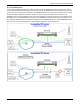
Chapter 5: Phone Book Configuration Sample Configuration: IP to Cellular Call Flow This sample section will show the process of making a call from a PBX extension and routing it to its end point using an MVPGSM. The graphic below represents the ‘big ‘picture’ of the process; below that will be brief statements showing the steps of the process with a short statement describing the flow. Double arrows show the direction of flow within the statement.
Chapter 5: Phone Book Configuration Dial tone in sent to PBX from << MVPGSM: A user dials digits which are sent to the >> cellular network for call routing: The call is placed from the cellular network to the intended >> end point (a cell phone, PSTN phone or PBX): Call Forwarding Call Forwarding is a feature of the Inbound Phone Book for IP calls and can be set to ‘Unconditional’ or ‘Busy’ as needed.
Chapter 5: Phone Book Configuration Making a Call: Load Balancing Calls made through an MVPGSM unit can be routed according to the Load Balancing setting. There are three types of load balancing in the MVPGSM: First Available, LUF (Least Used First), and RR (Round Robin). Load Balancing Options Should you be using SIM cards that have limited service times, there are three load balancing styles that can be employed to maximize your use and reduce extra charges.
Chapter 5: Phone Book Configuration Sample Configuration: Cellular to IP Call Flow Handling Options There are several options available when handling cellular to IP calls; all of which can be stacked on top of each other (used together). Calls can also be routed based on the incoming dialed digits, but the reliability of these digits is not guaranteed due to the differences in technologies. The various options are described below. Multi-Tech Systems, Inc.
Chapter 5: Phone Book Configuration CLIP Routing: Calls are accepted or rejected based on the calling number. In the United States, this includes the leading “1” (so 555-123-4444 is the same as 1555-123-444 for CLIP routing purposes). Accepted calls are routed over IP based on the CLIP routing reference to the Outbound Phone Book (destination pattern). Auto Call: Located in the Configuration | Voice/Fax section, Auto Call can be enabled with a number selected from the Outbound Phone Book.
Chapter 5: Phone Book Configuration Sample Inbound Phone Book The basic purpose of the Inbound Phone Book is to create rules for routing incoming IP calls. As in the samples previously shown, the phone books play an integral part in the call process. From the sample above for ‘Making a Call,’ we would have a basic Inbound Phone Book entry as shown below if that extension (extension number 301) was to use Channel 1: Multi-Tech Systems, Inc.
Chapter 5: Phone Book Configuration If the SIMs have a calling plan other than unlimited, we would then apply load balancing as shown in the second sample ‘Making a Call: Load Balancing.’ For this we would create a Load Balancing Group as shown below. Here we will use LUF load balancing for the MVPGSM.
Chapter 5: Phone Book Configuration Sample Outbound Phone Book The Outbound Phone Book is the director of where calls will be routed from the cellular network to the IP network – whether that is to a specific phone number, an available extension (Any Number) or to the IP address of a SIP device or remote VOIP unit for resending as a local call. As in the example previously shown, the phone books play an integral part in the processing of calls.
Chapter 5: Phone Book Configuration CLIP Routing Example With CLIP routing, you can create rules or even specific numbers that will be routed using the Outbound Phone Book to specified recipients. As an example, we will set CLIP routing to take all calls from the 763 area code with a 555 prefix and have them directed to the operator on the local PBX. First, the CLIP routing screen is shown below.
Chapter 5: Phone Book Configuration Auto Call Example In cases where you want incoming GSM calls automatically routed, the Auto Call feature may be used to handle this. In this example, SIM on Channel 4 has a number of 763-555-4444 and we want all calls received by this number to go to the Sales department at extension 333.
Chapter 5: Phone Book Configuration CLIP Routing used with Auto Call Used together, CLIP Routing and Auto Call can handle incoming traffic efficiently. With a populated CLIP routing table, an incoming call will first be compared to all of the entries in the CLIP Routing table looking for a match (full number or partial as the rules are set) and if no match is found, Auto Call will route the call according to the Auto Call settings.
Chapter 5: Phone Book Configuration Call Forwarding Example Another call handling option will be used in this example: Call Forwarding. This sets the channels to forward on a ‘busy,’ ‘no reply’ and ‘not reachable’ signal and to disable the call waiting feature. This is accomplished by checking the Call Forward box to ‘Enable’ as shown below. You then need to add a phone number in the Forward Destination field.
Chapter 5: Phone Book Configuration Local Survivability In cases where the connectivity to the network is not available (no response received from the IP Address/URL set in Local Survivability – Link Monitor Details), Local Survivability can route calls strictly through the available entries found in the Inbound and Outbound Phone Books. IP Survivability utilizes the Outbound Phone Book for call routing while Internal Survivability uses the Inbound Phone Book.
Chapter 5: Phone Book Configuration Internal Survivability Example: You have an MVPGSM with Channel 1 using SIP extension 301 and Channel 2 using SIP extension 302. A GSM call is received on Channel 1 and is intended for a remote office (809) represented by the black arrows. Unfortunately, the survivability destination on the Internet is not responding, so Local Survivability mode is processed, represented by the red arrows.
Chapter 5: Phone Book Configuration Phone Book Descriptions Outbound Phone Book/List Entries Some of the SIP-related fields in the “Details” section may be grayed out. Multi-Tech Systems, Inc.
Chapter 5: Phone Book Configuration Add/Edit Outbound Phone Book Enter Outbound Phone Book data for your MultiVOIP GSM unit. Note that the Advanced button gives access to the Alternate IP Routing feature, if needed. Alternate IP Routing can be implemented in a secondary screen (as described after the primary screen field definitions below). The fields of the Add/Edit Outbound Phone Book screen are described in the table below. Multi-Tech Systems, Inc.
Chapter 5: Phone Book Configuration Add/Edit Outbound Phone Book: Field Definitions Field Name Accept Any Number Values checkbox Description When checked, “Any Number” appears as the value in the Destination Pattern field. The Any Number feature works differently depending on whether or not an external routing device is used (Proxy for SIP protocol). When no external routing device is used.
Chapter 5: Phone Book Configuration Clicking on the Advanced button brings up the Alternate Routing secondary screen. This feature provides an alternate path for calls if the primary IP network cannot or does not respond within the timeframe of the Round Trip Delay. Often in cases of failure, call traffic is temporarily diverted into the PSTN. However, this feature could also be used to divert traffic to a redundant (backup) unit in case one SIP end point fails.
Chapter 5: Phone Book Configuration Inbound Phone Book/List Entries The “Details” and “Registration Options” sections will display information based on the setup and protocols chosen. Multi-Tech Systems, Inc.
Chapter 5: Phone Book Configuration Add/Edit Inbound Phone Book Multi-Tech Systems, Inc.
Chapter 5: Phone Book Configuration Enter Inbound Phone Book data for your MultiVOIP GSM. The fields of the Add/Edit Inbound Phone Book screen are described in the table below. Add/Edit Inbound Phone Book: Field Definitions Field Name Values Description Accept Any Number checkbox When checked, “Any Number” appears as the value in the Remove Prefix field. The Any Number feature of the Inbound Phone Book does not work when an external routing device is used (Proxy for SIP protocol).
Chapter 5: Phone Book Configuration Authorized User Name and Password for SIP To enable the Registration Options on the Add/Edit Inbound Phone Book, you have to activate Use SIP Proxy Option on the Call Signaling, SIP Parameters Screen. Then add the IP address for the Primary Proxy in the SIP Proxy Parameters. This allows you to add a Username and Password to the Inbound Phone Book entry.
Chapter 6 – Using the Software Introduction This chapter will primarily cover the day to day operation and maintenance sections of the MultiVOIP GSM software. How to update the firmware and software are also covered here should either be needed. This section will mainly focus on the Statistics section of the configuration software, but there are references to a few of the other sections as they are used more in the daily operations than in a setup situation.
Chapter 6: Using the Software System Information screen This screen presents system information at a glance. It is found under the Configuration section and its primary use is in troubleshooting. The information presented in the figure below is for reference only and is not meant to be an exact match of your system. System Information Parameter Definitions Field Name Boot Version Values nn.nn alphanumeric Description Indicates the version of the boot code that is running on the VOIP.
Chapter 6: Using the Software Statistics Section Ongoing operation of the MVPGSM, whether it is in a MVPGSM/PBX setting or MVPGSM/Telco-office setting, can be monitored for performance using the Statistics functions of the MVPGSM software. The following screens are examples of what can be shown and are followed by detailed descriptions of the categories involved. The model and signaling used will affect what is available for display. Call Progress Multi-Tech Systems, Inc.
Chapter 6: Using the Software Call Progress Details: Field Definitions Field Name Channel Duration Mode Voice Coder IP Call Type IP Call Direction Packets Sent Packets Rcvd Bytes Sent Bytes Rcvd Packets Lost Gateway Name (from) IP Address (from) Options Values 1-n Call Details H/M/S Voice or FAX G.723, G.729, G.711, etc. SIP incoming, outgoing Packet Details integer value integer value integer value integer value integer value From – To Details alphanumeric string n.n.n.
Chapter 6: Using the Software Call Progress Details: Field Definitions (continued) Field Name Values Description Supplementary Services Status SIP Call on Hold alphanumeric Describes held call by its IP address source, location/gateway identifier, and hold duration. Location/gateway identifiers come from Gateway Name field in Phone Book Configuration screen of remote VOIP. GSM Call on Hold alphanumeric Displays the phone number/SIP URL of a call that is on hold.
Chapter 6: Using the Software Wireless Statistics Wireless Statistics parameters Field Name Select Channel SIM-ID Plan Type* Recharge Date* Recharge Time* Delete Delete All Number of Entries Details Values Description 1–2 Select the channel that you want to see statistics for. number This will display the ID number of the SIM card on the selected channel. SIM plan This will display the plan that the SIM card has.
Chapter 6: Using the Software Endpoint Statistics SIP Server Endpoint Statistics Endpoint Name Status Max Expiry Time No. of Entries Unregister Details Registration Type Endpoint Type Initiated Call Count Received Call Count Contact Address Port Multi-Tech Systems, Inc. list column list column list column number button Displays the name of the endpoint. Shows the status of the endpoint. Displays the maximum set time to expire. Displays the total number of entries in the section above.
Chapter 6: Using the Software Logs The table below describes the fields of the Logs screen. Multi-Tech Systems, Inc.
Chapter 6: Using the Software Logs Screen Details: Field Definitions Field Name Log # column Values 1 or higher Start Date, Time column Duration column Type Status column dd:mm:yyyy hh:mm:ss hh:mm:ss SIP success or failure Incoming, outgoing voice or FAX gateway name gateway name Special Buttons -----Call Details Coder protocol "Normal" or "Local" inband, out of band IP Direction Mode column From column To column Previous Next First Last Delete File Voice coder Disconnect Reason DTMF Capability Outboun
Chapter 6: Using the Software IP Statistics UDP versus TCP (User Datagram Protocol versus Transmission Control Protocol) UDP provides unguaranteed, connectionless transmission of data across an IP network. By contrast, TCP provides reliable, connection-oriented transmission of data. Both TCP and UDP split data into packets called “datagrams.
Chapter 6: Using the Software IP Statistics: Field Definitions Field Name IP Address Values n.n.n.n “Clear” button Total Packets Transmitted integer value Received integer value Received integer with Errors value UDP Packets Description IP address of the MultiVOIP GSM. For an IP address to be displayed here, the MultiVOIP GSM must have DHCP enabled. Its IP address, in such a case, is assigned by the DHCP server. Clears packet tallies from memory. Sum of packets of all types.
Chapter 6: Using the Software Link Management The Link Management screen is essentially an automated utility for pinging endpoints on your VOIP network. This utility generates pings of variable sizes at variable intervals and records the response to the pings. Link Management screen Field Definitions Field Name Values Description Monitor Link fields IP Address to Ping n.n.n.n This is the IP address of the target endpoint to be pinged.
Chapter 6: Using the Software Servers SIP Proxies This window lists all the SIP proxy servers configured and the active server with which the system is registered. SIP Proxies (Statistics, Servers): Field Definitions Field Name IP Address Port Values n.n.n.n port Type Primary, Alternate registered, not registered Status Multi-Tech Systems, Inc. Description The IP address of the SIP proxy by which the MultiVOIP GSM is governed.
Chapter 6: Using the Software Advanced Packetization Time You can use the Packetization Time screen to specify definite packetization rates for coders selected in the Voice/FAX Parameters screen (in the “Coder Options” group of fields). The Packetization Time screen is accessible under the “Advanced” options entry in the sidebar list of the main VOIP software screen. In dealing with RTP parameters, the Packetization Time screen is closely related to both Voice/FAX Parameters and to IP Statistics.
Chapter 6: Using the Software MultiVOIP GSM Program Menu Items After the MultiVOIP GSM program is installed on the PC, it can be launched from the Programs group of the Windows Start menu ( Start | Programs | MultiVOIP GSM x.xx | … ). In this section, we describe the software functions available on this menu. Several basic software functions are accessible from the MultiVOIP GSM software menu, as shown below.
Chapter 6: Using the Software “Downloading” here refers to transferring program files from the PC to the nonvolatile “flash” memory of the MultiVOIP GSM. Such transfers are made via the PC’s serial port. This can be understood as a “download” from the perspective of the MultiVOIP GSM unit. When new versions of the MultiVOIP GSM software become available, they will be posted on Multi-Tech’s website.
Chapter 6: Using the Software Setting a Password Windows Interface After a user name has been designated and a password has been set, that password is required to gain access to any functionality of the MultiVOIP GSM software. Only one user name and password can be assigned to a VOIP unit. The user name will be required when communicating with the MultiVOIP GSM via the web browser interface. NOTE: Record your user name and password in a safe place.
Chapter 6: Using the Software When the MVPGSM program asks for the password at launch of program, if CANCEL is selected, the program will simply shut down. The MVPGSM program will produce an error message if an invalid password is entered. Password Reset 1. Connect your PC serial COM port to the command port on the back of the MultiVOIP unit. 2. Open HyperTerminal or other communications software and set the software COM port to match the settings of the COM port that is attached to the MultiVOIP.
Chapter 6: Using the Software 10. The shortcut tab should be opened by default. In the ‘Target:’ text box, put a space, a minus sign and the letter p after the last double quotation mark. Example: "C:\Program Files\Multi-Tech Systems\MultiVOIP 15.11\multivoip.exe" –p 11. 12. 13. 14. Click OK. Now double click on the Configuration shortcut icon. It will ask for confirmation on resetting the password. Click OK. It will now asking for new username and password. Enter your desired username and password.
Chapter 6: Using the Software FTP Server File Transfers (“Downloads”) Multi-Tech has built an FTP server into the MultiVOIP GSM unit. Therefore, file transfers from the controller PC to the VOIP unit can be done using an FTP client program or even using a browser (e.g., Internet Explorer, Netscape, or Firefox, used in conjunction with Windows Explorer). The terminology of “downloads” and “uploads” gets a bit confusing in this context.
Chapter 6: Using the Software 3. Install FTP Client Program or Use Substitute. You should install an FTP client program on the controller PC. FTP file transfers can be done using a web browser (e.g., Firefox or Internet Explorer) in conjunction with a local Windows browser a (e.g., Windows Explorer), but this approach is somewhat clumsy (it requires use of two application programs rather than one) and it limits downloading to only one VOIP unit at a time.
Chapter 6: Using the Software 6. Contact MultiVOIP GSM FTP Server. You must make contact with the FTP Server in the VOIP using either a web browser or FTP client program. Enter the IP address of the MultiVOIP GSM’s FTP Server. If you are using a browser, the address must be preceded by “ftp://” (otherwise you’ll reach the web interface within the MultiVOIP GSM unit). 7. Log In. Use the User Name and password established in item #2 above.
Chapter 6: Using the Software Download with FTP Client Program: • In the local directory browser of the FTP client program, locate the directory holding the MultiVOIP GSM program files. The default location will be C:\Program Files \Multi-Tech Systems \MultiVOIP GSM xxxx yyyy (where x and y represent MultiVOIP GSM model numbers and software version numbers). • In the FTP client program window, drag-and-drop files from the local browser pane to the pane for the MultiVOIP GSM FTP server.
Chapter 6: Using the Software Web Browser Interface You can control the MultiVOIP GSM unit with a graphic user interface (interface) based on the common web browser platform. Qualifying browsers are Internet Explorer 6+, Netscape 6+, and Mozilla Firefox 1.0+. Multi-Tech Systems, Inc.
Chapter 6: Using the Software MultiVOIP GSM Web Browser Interface Overview Function Configuration Prerequisite Browser Version Requirement Java Requirement Remote configuration and control of MultiVOIP GSM units. Local Windows interface must be used to assign IP address to MultiVOIP GSM. Internet Explorer 6.0 or higher; or Netscape 6.0 or higher; or Mozilla Firefox 1.0 or higher. Java Runtime Environment version 1.4.
Chapter 6: Using the Software When installation is complete, the Java program runs automatically in the background as a plug-in supporting the MultiVOIP GSM web interface. No user actions are required. After the Java program has been installed, you can access the MultiVOIP GSM using the web browser interface. Close the MultiVOIP GSM Windows interface. Start the web browser. Enter the IP address of the MultiVOIP GSM unit. Enter a password when prompted.
Chapter 6: Using the Software SysLog Server Functions Multi-Tech has built SysLog server functionality into the software of the MultiVOIP GSM units. SysLog is a de facto standard for logging events in network communication systems. To implement this functionality, you will need a SysLog client program (sometimes referred to as a “daemon”). SysLog client programs, both paid and freeware can be obtained from Kiwi Enterprises (search the Internet for kiwi syslog daemon), among other firms.
Appendix A – Ports & Cable Pin-outs Command Cable RJ-45 Connector End-to-End Pin Info 1 2 3 4 5 6 7 8 RJ-45 connector plugs into Command Port of MultiVOIP GSM. DB-9 connector plugs into serial port of command PC (which runs MultiVOIP GSM configuration software). Ethernet Connector The functions of the individual conductors of a MultiVOIP GSM Ethernet port are shown on a pin-by-pin basis below.
Appendix B – Regulatory Information EMC, Safety, and R&TTE Directive Compliance The CE mark is affixed to this product to confirm compliance with the following European Community Directives: Council Directive 2004/108/EC of 31 December, 2004 on the approximation of the laws of Member States relating to electromagnetic compatibility, and Council Directive 2006/95/EC 12 December, 2006 on the harmonization of the laws of Member States relating to electrical equipment designed for use within certain voltage lim
Appendix B: Regulatory Information Industry Canada This Class A digital apparatus meets all requirements of the Canadian Interference-Causing Equipment Regulations. Cet appareil numérique de la classe A respecte toutes les exigences du Règlement Canadien sur le matériel brouilleur. Canadian Limitations Notice Notice: The Industry Canada label identifies certified equipment. This certification means that the equipment meets certain telecommunications network protective, operational and safety requirements.
Appendix C – Additional Phone Book Examples MVPGSM-to-MVPGSM The basic setup would consist simply of two VOIPs able to communicate via IP address, with preset phone numbers entered into the Phone Book of each unit, with the Inbound Phone Book of one unit containing the exact same information as the Outbound Phone Book of the other unit and vice-versa. This is the underlying concept behind the Phone Books – they are the reverse of each other so that they match information to accomplish the connections.
Appendix C: More Phone Book Examples Example Inbound Phone Books The basic purpose of the Inbound Phone Book is to create rules for routing incoming IP calls. Below you will find the Inbound Phone Book settings for the examples that were detailed in the sample Phone Book Configurations above. Example 1: Local VOIP has 763-555-4321 in the Inbound Phone Book while the Remote VOIP has 612-555-1234 in the Inbound Phone Book.
Appendix D – Waste Electrical and Electronic Equipment (WEEE) Statement July, 2005 The WEEE directive places an obligation on EU-based manufacturers, distributors, retailers and importers to take-back electronics products at the end of their useful life. A sister Directive, ROHS (Restriction of Hazardous Substances) complements the WEEE Directive by banning the presence of specific hazardous substances in the products at the design phase.
Appendix E – C-ROHS HT/TS Substance Concentration 依照中国标准的有毒有害物质信息 根据中华人民共和国信息产业部 (MII) 制定的电子信息产品 (EIP) 标准-中华人民共和国《电子信息产品污染控制管理办法》(第 39 号),也称作中国 RoHS,下表列出了 Multi-Tech Systems Inc.
INDEX A L Antenna Requirements ...............................................................8 Auto Call Example .....................................................................79 Auto Disconnect .......................................................................39 AutoCall ....................................................................................39 LED descriptions ......................................................................... 6 Link Management fields ....................
SIP Call Signaling .......................................................................45 SIP Call Signaling parameter definitions ...................................45 SIP Server Definitions................................................................49 SMTP .........................................................................................53 SMTP parameters definitions ...................................................54 Software Installation...................................................