Model MT5600BA Model MT5600BL Data/Fax Modem User Guide
MultiModemII User Guide Models MT5600BA and MT5600BL P/N S0000129 Revision C ©1999-2001 by Multi-Tech Systems, Inc. All rights reserved. This publication may not be reproduced, in whole or in part, without prior expressed written permission from Multi-Tech Systems, Inc. Multi-Tech Systems, Inc. makes no representations or warranties with respect to the contents hereof and specifically disclaims any implied warranties of merchantability or fitness for any particular purpose.
FCC Part 15 NOTE: This equipment has been tested and found to comply with the limits for a Class B digital device, pursuant to Part 15 of the FCC Rules. These limits are designed to provide reasonable protection against harmful interference in a residential installation. This equipment generates, uses, and can radiate radio frequency energy, and if not installed and used in accordance with the instructions, may cause harmful interference to radio communications.
MultiModemII User Guide Contents Chapter 1: Introduction Introduction ............................................................................................................................. 2 Product Description ................................................................................................................ 2 Features .................................................................................................................................... 2 What Is in Your Modem Package? ..
MultiModemII User Guide Contents AT Commands ...................................................................................................................... 31 S-Registers .............................................................................................................................. 48 Result Codes .......................................................................................................................... 53 Chapter 5: Remote Configuration Introduction ................
MultiModemII User Guide Contents Appendix B: Technical Specifications .................................................................................. 85 Appendix C: Loopback Tests Introduction ........................................................................................................................... 87 Local Analog Loopback Test (V.54 Loop 3) ...................................................................... 87 Remote Digital Loopback Test (V.54 Loop 2) .............................
1 Introduction
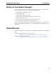
MultiModemII User Guide 1 Introduction Introduction Congratulations on your purchase of the MultiModemII modem. You have acquired one of the finest intelligent data/fax modems available today from one of the world’s oldest modem manufacturers: Multitech Systems, Inc. This user guide will help you install, configure, test and use your modem. Product Description The MultiModemII MT5600BA and MT5600BL modems incorporate the K56flex™ and V.
MultiModemII User Guide 1 Introduction Data • Supports K56flexTM and ITU-T V.90 speeds plus 33.6K, 31.2K, 28.8K, 26.4K, 24K, 21.6K, 19.2K, 16.8K, 14.4K, 12K, 9.6K, 7.2K, 4.8K, 2.4K, 1.2K, and 0–300 bps. Note: Under the 56K bps standards, you can asymmetrically download data from an ISP at speeds up to 53K bps, but upload only at speeds up to 33.6K bps. Clientto-client operation, including leased line operation, is also limited to 33.6K bps.
MultiModemII User Guide 1 Introduction What Is in Your Modem Package? Your modem package has several components. Make sure you have them all before trying to operate your modem.
2 Installation
MultiModemII User Guide 2 Installation Introduction This chapter shows you step-by-step how to set up your Multi-Tech MultiModemII, check it out, and make your first calls.
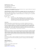
MultiModemII User Guide 2 Installation Step 1: Connect the Modem to Your System Turn off your computer. Placing the modem in a convenient location, connect it to your computer’s serial port, to the telephone line, to your leased line, to AC power, and, optionally, to your telephone. PHONE LINE LEASED EIA RS232C VOLUME POWER Figure 2-1. MT5600BL connections.
MultiModemII User Guide 2 Installation Two-Wire Leased Line Connection MT5600BA: Plug one end of a two-wire phone cable into the modem’s LINE jack, and connect the other end to a leased line wall jack or terminals. MT5600BL: Plug one end of a two-wire phone cable into the modem’s LEASED jack, and connect the other end to a leased line wall jack or terminals.
MultiModemII User Guide 2 Installation Step 2: Install the Modem Driver If you use Windows 95, Windows 98, Windows Me, Windows NT 4.0, or Windows 2000, you must install the modem driver. (If you use Windows 3.1 or another operating system, skip this step and go to Step 3.) Installing the ModemDriver 1. Make sure your modem is connected properly, and then turn on your computer. Windows should detect your new modem and open the Install New Modem wizard.
MultiModemII User Guide 2 Installation Step 3: Install and Configure Your Software You may use either the communication program included with your modem or a third-party program. Communication programs designed for Windows 95/98/Me and Windows NT/2000 normally do not need to be manually configured, since they use the Plug and Play configuration supplied by the Windows modem driver.
3 Using the Front Panel
MultiModemII User Guide 3 Using the Front Panel Introduction Like any modem, your Multi-Tech modem operates only under the control of a communication program, such as the Phone Tools program included with the modem. It also operates under other general-purpose data communication programs, such as Windows Terminal and HyperTerminal. For information on how to use the modem with the communication program of your choice, please refer to the program’s documentation.
MultiModemII User Guide 3 Using the Front Panel Terminal Ready. The TR indicator lights when a communication program is using the modem. It means the modem is ready for an outgoing or incoming call. It goes off when the communication program disconnects the serial port. When it goes off, a connected modem will disconnect. Test Mode. The TM indicator lights when the modem is in test mode.
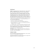
MultiModemII User Guide 3 Using the Front Panel Menu Overview Trunks Limbs Branches Twigs Manual selection Automatic selection 14
MultiModemII User Guide 3 Using the Front Panel Status Trunk The Status Trunk shows the current operating status of the modem. Limb changes are automatic, but certain options can be accessed by pressing the à button. Note that when the modem is online, pressing the à button shows the connect status, including the data speed, connection type, and compression type.
MultiModemII User Guide 3 Using the Front Panel Basic Options Trunk Use the Basic Options Trunk to configure the modem’s basic operating conditions. When entering a number, use the áß and â buttons to scroll through a list of digits and characters. To go to the next position, press the à button. To back up or to exit without dialing, press the à button several times.
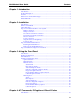
MultiModemII User Guide 3 Using the Front Panel Basic Options Trunk, continued Limbs Branches Twigs Continued from previous page 17
MultiModemII User Guide 3 Using the Front Panel Advanced Options Trunk Use the Advanced Options Trunk to configure RS-232, dial backup, and callback security options. When entering a number or password, use the áß and â buttons to select a character or digit. To go to the next position, press the à button. To backspace or to exit, press the à button several times.
MultiModemII User Guide 3 Using the Front Panel Advanced Options Trunk, continued Limbs Branches Twigs Continued from previous page 19
MultiModemII User Guide 3 Using the Front Panel Remote Configuration Options Trunk Use the Remote Configuration Options Trunk to enable or disable remote configuration on the modem, and to change the password. When entering the password, use the áß and â buttons to scroll through the alphabet. To go to the next character position, press the à button. To backspace or to exit, press the à button several times.
MultiModemII User Guide 3 Using the Front Panel Phone Number Memory Options Trunk The MultiModemII can store up to four telephone numbers for speed dialing. Use the Phone Number Memory Options Trunk to store, list, and dial these numbers. When entering a number, use the áß and â buttons to scroll through the available digits and dialing commands. To go to the next position, press the à button. To backspace or to exit, press the à button several times.
MultiModemII User Guide 3 Using the Front Panel Menu Options This section describes important LCD screens and options. Many, but by no means all, of the options have AT command equivalents. Status Status screens display the current status of the modem. Though limb changes are automatic, certain options can be selected by pressing the à button. STATUS = IDLE. The modem is ready but inactive. This screen appears when the modem is first turned on, and is the starting point for accessing all other screens.
MultiModemII User Guide 3 Using the Front Panel Basic Options The following screens are used to configure the modem’s basic operating conditions. ONLINE OPTIONS. The following screens are used to configure the online operation of the modem: LINE TYPE OPTIONS. Use the à and Enter buttons to select from the following line types: dial-up (PSTN), two-wire leased line originate or answer, and four-wire leased line originate or answer. ERROR CORRECTION OPTIONS.
MultiModemII User Guide 3 Using the Front Panel COMMAND MODE OPTIONS. The following screens are used to configure result code responses. ENABLE/DISABLE RESPONSE. Use the à and Enter buttons to enable or disable the sending of result codes to the computer. Same as the Q0 and Q1 commands. VERBOSE/TERSE RESPONSE. Use the à and Enter buttons to select verbose or terse result codes. Same as the V0 and V1 commands. ENABLE/DISABLE CMD MODE.
MultiModemII User Guide 3 Using the Front Panel Advanced Options RS232 OPTIONS. The following screens are used to configure the RS-232 interface. DTR OPTIONS. Use the à and Enter buttons to select how the modem responds to the high to low transition of the DTR signal sent by the computer. DTR NORMAL causes the modem to hang up; IGNORE DTR allows operation with computers that do not provide DTR; and RESET ON DTR â causes the modem to perform a soft reset as if the Z command were received.
MultiModemII User Guide 3 Using the Front Panel CALLBACK SECURITY. Use the à and Enter buttons to turn callback security on or off. Same as the #DB0 and #DB1 commands. For more information about callback security, see Chapter 6, “Callback Security.” PASSWORD SETUP. Use to enter callback security passwords in memory locations 1–30. Each password must be six to ten characters in length. To scroll through a list of digits and characters, press the áß and â buttons.
MultiModemII User Guide 3 Using the Front Panel Remote Configuration Options The following screens are used to configure remote configuration options. For more information about remote configuration, see Chapter 5, “Remote Configuration.” ENABLE/DISABLE R.C. Use the à and Enter buttons to turn remoteconfiguration on or off. REMOTE CONFIG. PASSWORD. Use to enter the remote configuration password. To scroll through a list of digits and characters, press the áß and â buttons.
MultiModemII User Guide 3 Using the Front Panel Caller ID Options Press the à and Enter buttons to enable formatted (FCID) or unformatted (UCID) Caller ID, or to disable Caller ID altogether. Same as the #CID=0, #CID=1, and #CID=2 commands. Note: Because Caller ID information is sent between the first and second ring, register S0 must be set to 2 or more rings for the modem to receive Caller ID information.
4 AT Commands, S-Registers & Result Codes
MultiModemII User Guide 4 AT Commands, S-Registers, and Result Codes Introduction AT commands are used to control the operation of your modem. They are so called because each command must be preceded by the characters AT to get the ATtention of the modem. AT commands can be issued only when the modem is in command mode or online command mode. The modem is in command mode whenever it is not connected to another modem.
MultiModemII User Guide 4 AT Commands, S-Registers, and Result Codes AT Commands Command: Values: Description: AT Command: Values: Description: ENTER Key n/a Press the ENTER or RETURN key to execute most commands. Command: Values: Description: A Answer n/a Answers an incoming call before the final ring. Command: Values: Description: A/ Repeat Last Command n/a Repeats the last command string. Do not precede this command with AT. Do not press ENTER to execute.
MultiModemII User Guide 4 AT Commands, S-Registers, and Result Codes @ Wait for silence. Causes the modem to wait for 5 seconds of silence before processing the next part of the command. If silence is not detected within the time set in register S7, the modem returns a NO ANSWER or BUSY code. ^ Toggle data calling tone on or off. Applies only to current dialing attempt. & Detect credit card “bong” tone.
MultiModemII User Guide Command: Values: Default: Description: 4 AT Commands, S-Registers, and Result Codes Ln L1 Monitor Speaker Volume n=1 1 Select low volume. Note: Use the M command to turn the speaker on or off. Command: Value: Default: Description: L5 Display Legacy Parameters 5 None Displays the current values for the error correction, flow control, data compression, and serial port speed commands. Example: atl5 &E2 &E3 &E15 $SB115200 OK Note: Use the &V command to display the other parameters.
MultiModemII User Guide Command: Values: Default: Description: 4 AT Commands, S-Registers, and Result Codes On O0 O1 Return Online to Data Mode 0 or 1 None Exit online command mode and return to online data mode without a retrain. Normally used after a +++ escape (see +++AT escape sequence). Exit online command mode and return to online data mode after a retrain.
MultiModemII User Guide Command: Values: Default: Description: 4 AT Commands, S-Registers, and Result Codes Wn W0 W1 W2 Connect Message Control n = 0, 1, or 2 0 The CONNECT result code reports the serial port speed only. The CONNECT result code reports the line speed, the error correction protocol, and the serial port speed, respectively. The CONNECT result code reports the line speed only.
MultiModemII User Guide 4 AT Commands, S-Registers, and Result Codes Command: Values: Default: Description: &Cn Data Carrier Detect (DCD) Control n = 0 or 1, 2 or 3, 4 or 5 1, 3, 4 &C0 Forces the DCD circuit to always be high. &C1 DCD goes high when the remote modem’s carrier signal is detected, and goes low when the carrier signal is not detected. &C2 DCD goes high 500 milliseconds after the CONNECT message is generated. &C3 DCD goes high when the CONNECT message is generated. &C4 Disables &C5 command.
MultiModemII User Guide Command: Values: Default: Description: 4 AT Commands, S-Registers, and Result Codes &En Modem-Initiated Flow Control n = 3, 4, or 5 4 &E3 Flow control disabled. &E4 CTS/RTS hardware flow control. &E5 XON/XOFF software flow control. Note: See also the L5 and &K commands. Command: Values: Default: Description: &En V.42bis Data Compression n = 14 or 15 15 &E14 V.42bis data compression disabled. &E15 V.42bis data compression enabled. Note: This command controls only V.
MultiModemII User Guide Command: Values: Defaults: Description: 4 AT Commands, S-Registers, and Result Codes &Kn Flow Control Selection n = 0, 3, 4, 5, or 6 3 (data modem mode) 6 (fax modem and voice modes) &K0 Disables flow control. &K3 Enables CTS/RTS hardware flow control. &K4 Enables XON/XOFF software flow control. &K5 Enables transparent XON/XOFF flow control. &K6 Enables both RTS/CTS and XON/XOFF flow control.
MultiModemII User Guide Command: Values: Default: Description: 4 AT Commands, S-Registers, and Result Codes &Rn Clear to Send (CTS) Control n = 0 or 1 1 &R0 Let the CTS state follow the RTS state when online.. &R1 Force CTS high (ON). Note: This command applies only in synchronous mode. Command: Values: Default: Description: &Sn Data Set Ready (DSR) Control n = 0 or 1 0 &S0 Force DSR high (on) at all times. &S1 Let DSR go high only during a connection. Command: Values: Default: Description: &Tn V.
MultiModemII User Guide 4 AT Commands, S-Registers, and Result Codes Command: Values: Default: Description: &V1 Command: Values: Default: Description: &Wn Store Current Configuration n = 0 or 1 None &W0 Stores current modem settings in nonvolatile memory as Profile 0. Profile 0 is loaded instead of the factory defaults at power-on (if &Y0 is set) and by the ATZ command. &W1 Stores current modem settings in nonvolatile memory as Profile 1.
MultiModemII User Guide Command: Values: Default: Description: 4 AT Commands, S-Registers, and Result Codes %Cn Data Compression Control n = 0, 1, 2, or 3 3 Enables or disables data compression negotiation. The modem can only perform data compression on an error-corrected link. %C0 Disables data compression. %C1 Enables MNP 5 data compression negotiation. %C2 Enables V.42bis data compression negotiation. %C3 Enables both V.42bis and MNP 5 data compression negotiation. Note: This command controls both V.
MultiModemII User Guide 4 AT Commands, S-Registers, and Result Codes Command: Values: Default: Description: \An Command: Values: Default: Description: \Bn Transmit Break n = 0–9 in 100 ms units 3 In non-error-correction mode only, sends a break signal of the specified length to a remote modem. Works in conjunction with the \K command.
MultiModemII User Guide Command: Values: Default: Description: 4 AT Commands, S-Registers, and Result Codes \Nn \N0 \N1 \N2 \N3 \N4 \N5 Command: Values: Default: Description: \Vn \V0 \V1 Error Correction Mode Selection n = 0–5 3 Normal (non-error correction) mode with data buffering. (Forces &Q6.) Direct mode. Equivalent of &M0 and &Q0 modes. (Forces &Q0.) V.42/MNP reliable (error-correction) mode. The modem attempts first a V.42 connection and then an MNP connection.
MultiModemII User Guide 4 AT Commands, S-Registers, and Result Codes +MS=? Reports supported options in the format (list of supported mod values),(list of supported automode values),(list of supported min_RX_rate values),(list of supported max_RX_rate values), (list of supported x_law values), (list of supported reserved values),(list of supported max_TX_rate values). Example: (0,1,2,3,9,10,11,56,64,69),(0,1),(300-33600),(30056000),(0,1),(0,1),(300-33600).
MultiModemII User Guide 4 AT Commands, S-Registers, and Result Codes x_law An optional number that specifies the PCM code type for 56K modulation. The options are: 0 = µ-Law—used in North America and Japan (default) 1 = A-Law—used outside North America and Japan The modem automatically selects A-Law or µ-Law if the server sends the Conexant ID. Note that the ATZ command restores the x_law value from NVRAM. You can also manually select A-Law or µ-Law using the %U command.
MultiModemII User Guide 4 AT Commands, S-Registers, and Result Codes Command: Values: Description: **n Command: Values: Description: *B View Numbers in Blacklist n/a If blacklisting is in effect, AT*B displays a list of numbers for which the last call attempted in the previous two hours failed. Permanently forbidden numbers as defined by country requirements do not appear in this list. If no numbers are blacklisted, only the OK result code is displayed.
MultiModemII User Guide 4 AT Commands, S-Registers, and Result Codes Command: #CID=n Values: Default: Description: Caller ID n = 0, 1, or 2 0 Enables or disables Caller ID recognition and reporting. #CID=0 Disables Caller ID. #CID=1 Enables formatted Caller ID reporting of ICLID SDM (Single Data Message) and MDM (Multiple Data Message) packets. #CID=2 Enables unformatted Caller ID reporting of any ICLID packet received after the first RING cycle, including SDM, MDM, or call waiting packets.
MultiModemII User Guide 4 AT Commands, S-Registers, and Result Codes S-Registers Certain modem values, or parameters, are stored in memory locations called Sregisters. Use the S command to read or alter the contents of S-registers (see previous section). Register Unit Range Default Description S0 1 ring 0, 1–255 1 Sets the number of rings before the modem answers. ATS0=0 disables autoanswer completely. S1 1 ring 0–255 0 Counts the rings that have occurred.
MultiModemII User Guide Register Unit 4 AT Commands, S-Registers, and Result Codes Range Default Description S13 decimal 0, 1–127 42 (*) Sets the ASCII code for the remote configuration escape character. ATS13=0&W disables remote configuration. S15 minutes 0, 10–255 30 Sets the length of time the modem waits after making a dial-up connection before it checks the lease line for restoral. A zero value disables dial backup.
MultiModemII User Guide Register Unit S36 4 AT Commands, S-Registers, and Result Codes Range decimal 0–7 Default 7 Description LAPM Failure Control. Specifies the fallback action to take in the event of an LAPM negotiation failure. These fallback options are initiated immediately upon connection if S48 is set to 128. If an invalid number is entered, S36 acts as if the default value has been entered. (See S48.) 0 Modem disconnects. 1 Modem stays online and a direct mode connection is established.
MultiModemII User Guide Register Unit S46 4 AT Commands, S-Registers, and Result Codes Range decimal 136, 138 Default 138 Description Enables or disables data compression: 136 Error correction without compression. 138 Error correction with compression. S48 decimal 0, 7, 128 7 Enables or disables LAPM negotiation. An invalid value is treated as a 128 value. 0 Disables negotiation and proceeds with LAPM. 7 Enables negotiation.
MultiModemII User Guide 4 AT Commands, S-Registers, and Result Codes Register Unit Range S95 decimal 0–15 Default 0 Description The bits in this register can be set to override some of the W command options. A bit set to a 1 in this register enables the corresponding result code regardless of the W setting. Bit 0 CONNECT result code indicates DCE speed instead of DTE speed. Bit 1 Append /ARQ to CONNECT XXX result code in error-correction mode. Bit 2 Enable CARRIER XXXX result code.
MultiModemII User Guide 4 AT Commands, S-Registers, and Result Codes Result Codes In command mode your modem can send the following responses, called result codes, to your computer. Result codes are used by communications programs and can also appear on your monitor.
MultiModemII User Guide Terse Verbose 62 63 64 66 67 69 70 77 78 79 80 81 84 150 151 152 153 154 155 156 157 158 159 160 161 162 165 166 167 168 169 170 171 172 173 174 175 176 177 180 180 181 181 182 182 183 183 184 184 185 4 AT Commands, S-Registers, and Result Codes Description CONNECT 24000 Connected at 24000 bps CONNECT 26400 Connected at 26400 bps CONNECT 28800 Connected at 28800 bps COMPRESSION CLASS 5 Connected with MNP Class 5 data compression COMPRESSION V.42 bis Connected with V.
MultiModemII User Guide 4 AT Commands, S-Registers, and Result Codes Terse Verbose Description 185 186 186 187 187 188 188 189 189 190 190 191 191 192 192 193 193 194 194 +F4 37333 bps data carrier detected (V.90 mode) Connected at 38667 bps (V.90 mode) 38667 bps data carrier detected (V.90 mode) Connected at 41333 bps (V.90) 41333 bps data carrier detected (V.90) Connected at 42667 bps (V.90) 42667 bps data carrier detected (V.90) Connected at 45333 bps (V.90) 45333 bps data carrier detected (V.
5 Remote Configuration
MultiModemII User Guide 5 Remote Configuration Introduction Remote configuration is a network management tool that allows you to configure modems anywhere in your network from one location. With password-protected remote configuration, you can issue AT commands to a remote MultiModemII modem for maintenance or troubleshooting as if you were on-site. Basic Procedure The following steps are valid regardless of whether the connection is established by the local or the remote MultiModemII modem. 1.
MultiModemII User Guide 5 Remote Configuration 3. To change the password, press áß or â to select the first character of the password, and then press à to go to the next character. Repeat until you have entered the entire password. 4. To cancel the new password, press à until the password is erased. To save the new password, press the Enter button. The next time you remotely configure the modem you must use the new password.
6 Callback Security
MultiModemII User Guide 6 Callback Security Introduction This chapter describes how to use callback security with your modem. Callback security protects your network from unauthorized access and helps control long distance costs. When callback security is enabled, all callers are requested to enter a password. If the password is invalid, the caller can try twice more before the modem hangs up.
MultiModemII User Guide 6 Callback Security Front Panel Method 1. Turn on the modem. 2. Starting at the STATUS screen, press the following buttons on the front panel to turn callback security on and off: • To turn on callback security, press â, â, à, â, â, à, à to display the CALLBACK ON? option, and then press the Enter button to select the option. When remote callback security is turned on, each caller is asked to enter a password, then is disconnected and called back by the modem.
MultiModemII User Guide 6 Callback Security 7. Press the Enter button again to go to the PASSWORD SETUP screen. 8. Press à, à to go to the ENTER PASSWORD #2? screen. 9. Repeat steps 3–7 to enter the next password. 10. Repeat as many times as necessary, up to memory location 30, until all passwords have been entered. Warning: There is no way to review an entry to confirm that it has been entered correctly.
MultiModemII User Guide 6 Callback Security 7. Press the Enter button again to go to the CALLBACK NUMBER screen. 8. Press à, à to go to the ENTER NUMBER #2? screen. 9. Repeat steps 3–7 to enter the next number. 10. Repeat as many times as necessary, up to memory location 30, until all numbers have been entered. Warning: There is no way to review an entry to confirm that it has been entered correctly.
MultiModemII User Guide 6 Callback Security Callback Security Commands The following AT commands are used with callback security. Command: #DBn Values: Default: Description: #DB0 #DB1 Callback Enable/Disable n = 0 or 1 0 Enables or disables callback security. When callback security is enabled, phone number memory locations 0–4, used for quick dialing and DTR dialing, become unavailable and are replaced by callback security memory locations 1–30.
MultiModemII User Guide 6 Callback Security Callback Assignments Form Location 01 02 03 04 05 06 07 08 09 10 11 12 13 14 15 16 17 18 19 20 21 22 23 24 25 26 27 28 29 30 Password Phone number 65
7 Leased Line Operation
MultiModemII User Guide 7 Leased Line Operation Introduction This chapter describes how to use the MultiModemII modem on a leased line. A leased line is a private, permanent, telephone connection between two points. Unlike normal dialup connections, a leased line is always active. The modems automatically connect when they are attached to the line and are turned on.
MultiModemII User Guide 7 Leased Line Operation 10. This completes the setup for two-wire leased line operation. Upon completion, the modem attempts to connect to the modem at the other end of the leased line. If the remote modem has not yet been configured for leased line operation, you may turn off the local modem until the remote one is ready. Four-Wire Setup 1. For four-wire leased line operation, connect one of the provided four-wire cables to the LEASED jack on the back of the MT5600BL modem.
MultiModemII User Guide 7 Leased Line Operation Dial Backup and Leased Line Restoral For four-wire leased line operation, the MT5600BL modem has a dial backup capability, in which the modem is connected to a standard dial-up line as well as to the leased line. If the leased line fails, the originate modem automatically dials and connects to the answer modem through the standard telephone network. While it is in dial backup mode, the MT5600BL periodically checks the leased line to see if it is operational.
MultiModemII User Guide 7 Leased Line Operation 8. To change the default restore time, press â to go to the TIME TO RESTORE (S15) screen, then press à, à. The ENTER TIME IN MINUTES screen appears. 9. Press the áß or â button several times to select the first digit in the number. 10. Press the à button to go to the next digit in the number. 11. Repeat steps 9 and 10 until you have entered a value between 10 and 255, or 0 to disable dial backup, and then press the Enter button to store it.
8 Solving Problems
MultiModemII User Guide 8 Solving Problems Introduction Your modem was thoroughly tested at the factory before it was shipped. If you are unable to make a successful connection, or if you experience data loss or garbled characters during your connection, it is possible that the modem is defective. However, it is more likely that the source of your problem lies elsewhere. The following symptoms are typical of problems you might encounter: • None of the LEDs light when the modem is on.
MultiModemII User Guide 8 Solving Problems The Modem Does Not Respond to Commands 4 Make sure the modem is plugged in and turned on. (See “None of the Indicators 4 4 4 4 4 4 4 4 Light.”) Make sure you are issuing the modem commands from data communication software, either manually in terminal mode or automatically by configuring the software. (You cannot send commands to the modem from the DOS prompt.) Make sure you are in terminal mode in your data communication program, then type AT and press ENTER.
MultiModemII User Guide 8 Solving Problems click Advanced, and select the new port address and/or interrupt. If you wish to use COM3 or COM4, note that COM3 shares an IRQ with COM1, as does COM4 with COM2, so you should change their IRQs to unused ones, if possible. Windows 9x: Right-click on My Computer, select Properties from the menu, click on the Device Manager tab, double-click on Ports, then double-click on the communication port your modem is connected to.
MultiModemII User Guide 4 8 Solving Problems behind a corporate phone system (PBX) with an internal dial tone that sounds different from the normal dial tone. In that case, the modem might not recognize the dial tone and might treat it as an error.
MultiModemII User Guide 4 4 4 8 Solving Problems Check for loose connections between the modem and the computer, the telephone jack, and AC power. You might have had a poor connection because of line conditions or the problem might have originated on the other end of the line. Try again. If you were online with a BBS or an online service like CompuServe, it might have hung up on you because of lack of activity on your part or because you exceeded your time limit for the day. Try again.
MultiModemII User Guide 8 Solving Problems Data Is Being Lost 4 If you are using data compression and a high speed serial port, set the serial port 4 4 4 4 baud rate to four times the data rate. Your UART might not be reliable at serial port speeds over 9600 bps or 19,200 bps. Turn off data compression, reset your serial port speed to a lower rate, or replace your serial port with a faster one. Make sure the flow control method you selected in software matches the method selected in the modem.
MultiModemII User Guide 8 Solving Problems Fax and Data Software Can’t Run at the Same Time 4 Communication devices can be accessed by only one application at a time. Under DOS or Windows 3.1x, you can run either your fax software or your datacomm software, but not both at the same time, unless you have a special communication device management application. In Windows 95, 98, and NT 4.
Appendixes
MultiModemII User Guide A Regulatory Compliance Appendix A: Regulatory Compliance FCC Part 68 Telecom 1. This equipment complies with part 68 of the Federal Communications Commission Rules. On the outside surface of this equipment is a label that contains, among other information, the FCC registration number. This information must be provided to the telephone company. 2. The suitable USOC jack (Universal Service Order Code connecting arrangement) for this equipment is shown below.
MultiModemII User Guide A Regulatory Compliance Manufacturer: Trade Name Model Number: FCC Registration No: Ringer Equivalence No: Modular Jack (USOC): Multi-Tech Systems, Inc. MultiModemII MT5600BA or MT5600BL AU7USA-33378-M5-E 0.1A RJ11C or RJ11W (single line) Service Center in USA: Multi-Tech Systems, Inc. 2205 Woodale Drive Mounds View, MN 55112 U.S.A.
MultiModemII User Guide A Regulatory Compliance Canadian Limitations Notice Notice: The ringer equivalence number (REN) assigned to each terminal device provides an indication of the maximum number of terminals allowed to be connected to a telephone interface. The termination on an interface may consist of any combination of devices subject only to the requirement that the sum of the ringer equivalence numbers of all the devices does not exceed 5.
MultiModemII User Guide A Regulatory Compliance International Modem Restrictions Some dialing and answering defaults and restrictions may vary for international modems. Changing settings may cause a modem to become non-compliant with national telecom requirements in specific countries. Also note that some software packages may have features or lack restrictions that may cause the modem to become non-compliant. New Zealand Telecom Warning Notice 1.
MultiModemII User Guide A Regulatory Compliance • There shall be no more than 10 call attempts to the same number within any 30-minute period for any single manual call initiation, and • The equipment shall go on-hook for a period of not less than 30 seconds between the end of one attempt and the beginning of the next attempt.
MultiModemII User Guide B Technical Specifications Appendix B: Technical Specifications Your MultiModemII modem meets the following specifications: Trade Name MultiModemII™ Model Number MT5600BA and MT5600BL Server-to-Client Data Rates K56flex or V.90 speeds when accessing a K56flex or V.
MultiModemII User Guide B Technical Specifications Transmission Level -11 dBm (dial-up—varies depending on country setting), -10 dBm (leased-line) Frequency Stability ±0.01% Receiver Sensitivity -43 dBm under worst-case conditions AGC Dynamic Range 43 dB Interface TIA/EIA RS-232C/ITU-T V.24/V.
MultiModemII User Guide C Loopback Tests Appendix C: Loopback Tests Introduction Each time you turn on your modem, it performs an automatic self-test to ensure proper operation. Your modem also has three diagnostic tests: local analog loopback, remote digital loopback, and local digital loopback. These ITU-T V.54 loopback tests isolate telephone circuit and transmission problems.
MultiModemII User Guide C Loopback Tests 2. Type AT and press ENTER; you should get an OK message. Type AT\N and press ENTER to disable error correction. 3. Type AT&T1 and press ENTER. This places your modem in analog loopback mode in the originate mode. A CONNECT message should appear on your display. The modem is now out of command mode and in a pseudo-online mode. 4. Note that the CD and TM indicators are on. If they are not on, there is a defect in your modem. 5. Enter characters from your keyboard.
MultiModemII User Guide C Loopback Tests 2. Open your communications software and go into terminal mode. Type AT and press ENTER; you should get an OK message. Type AT\N and press ENTER to disable error correction. Type AT+MS=9,1,9600,9600 and press ENTER to set the local modem to V.32 mode at 9600 bps. 3. Dial the remote modem and establish your online connection. 4. Type the escape sequence +++AT and press ENTER to bring your modem into online command mode. 5. Type AT&T6 and press ENTER.
MultiModemII User Guide C Loopback Tests Test procedure 1. Open your communication software and go into terminal mode. Type AT and press ENTER; you should get an OK message. Type AT\N and press ENTER to disable error correction. Type AT+MS=9,1,9600,9600 and press ENTER to set the local modem to V.32 mode at 9600 bps. 2. Dial the remote modem and establish your online connection. 3. Type the escape sequence +++AT and press ENTER to bring your modem into online command mode. 4. Type AT&T3 and press ENTER.
MultiModemII User Guide C Loopback Tests 3. Following the instructions in Chapter 7, set both modems to two-wire leasedline mode. One should be set as the originate modem and the other as the answer modem, but it does not matter which is which. 4. Turn on both units and wait for carrier detect (CD). 5. On the modem under test, short pins 2 and 3 of the RS-232C connector with a paper clip or other metal device. 6. Enter data from your keyboard.
MultiModemII User Guide D Warranty, Service, and Technical Support Appendix D: Warranty, Service, and Technical Support Limited Warranty Multi-Tech Systems, Inc. (MTS) warrants that this product will be free from defects in material or workmanship for a period of five years from the date of purchase or, if date of purchase is not provided, five years from the date of shipment, unless otherwise limited or prohibited by law.
MultiModemII User Guide D Warranty, Service, and Technical Support of the problem, a return shipping address (must have street address, not P.O. Box), a telephone number, and if the product is out of warranty, a check or purchase order for repair charges. Extended two-year overnight replacement agreements are available for selected products. Please refer to our Overnight Replacement Agreement at http:// www.multitech.com/PROGRAMS/orc/ for details on rates and coverages.
MultiModemII User Guide D Warranty, Service, and Technical Support Technical Support Multi-Tech Systems has an excellent staff of technical support personnel available to help you get the most out of your Multi-Tech product. If you have any questions about the operation of this unit, please call 800 972-2439 (USA and Canada) or 763 785-3500 (international and local). Please have modem information available. You can also contact Technical Support by e-mail at the following addresses: U.S.
MultiModemII User Guide E Upgrading the Modem Appendix E: Upgrading the Modem Introduction Your modem is controlled by semi-permanent software, called firmware, which is stored in flash memory. Firmware is nonvolatile; that is, it remains stored in memory when the modem is turned off. However, it can be changed by either the manufacturer or the user as bugs are fixed or new features are added.
MultiModemII User Guide E Upgrading the Modem Step 2: Identify the Current Firmware Version Identify the current version of the firmware at the Multi-Tech Web site. If your modem already has the current firmware, there is no need to update it. 1. Using your favorite Web browser, go to http://www.multitech.com/support/ MultiModemII/firmware.asp. 2. Scroll down the table to your modem model number. 3. Look at the firmware version number for your modem. 4.
MultiModemII User Guide E Upgrading the Modem 2. In the program’s terminal window, type AT&V and press ENTER to list your modem’s current parameters. 3. Record your parameters by saving the screens and sending them to your printer. 4. Type AT&F and press ENTER to clear your stored parameters and reset your modem to factory default. 5. Close the terminal program. Step 6: Upgrade the Modem’s Firmware Before you begin the following procedure, read the README.TXT file extracted from the upgrade archive file.
MultiModemII User Guide F Installing a Modem Under Linux Appendix F: Installing a Modem Under Linux Introduction This appendix explains how to install a modem on a computer operating under the Red Hat Linux 6.2 operating system. Other versions of Red Hat and other Linux operating systems should be similar. Briefly, in Linux, you do not need drivers for most standard external modems and most internal ISA bus modems. Programs in Linux commonly call upon the port, rather than the modem.
MultiModemII User Guide F Installing a Modem Under Linux Using the Modem to Call the Internet Linux allows different graphic user interfaces (GUI). In the following steps, we’ll use the Gnome Desktop GUI and assume that the Internet Service Provider (ISP) you are calling assigns you the Domain Name Service (DNS) and Internet Protocol (IP) addresses. For more information on DNS or IP, see the Linux OS owner’s manual or contact your ISP. 1.
MultiModemII User Guide G Pin Descriptions Appendix G: Pin Descriptions RS-232 Pin Descriptions Label Pin CGND 1 TD 2 Transmitted Data The DTE uses the TD line to send data to the modem for transmission over the telephone line or to transmit commands to the modem. RD 3 Received Data The modem uses the RD line to send data received from the telephone line to the DTE and to send modem responses to the DTE. RTS 4 Request to Send The RTS signal is used for hardware flow control.
MultiModemII User Guide G Pin Descriptions Label Pin I/O type Signal name/description RDL 21 RDL Remote Digital Loop Input to modem to enable RDL test. RI 22 Ring Indicator RI output high indicates the presence of a ring signal on the telephone line. 23 NC XCLK 24 XCLK External Clock Input to modem used in special synchronous applications. TM 25 TM Test Mode Output from modem to indicate modem is in one of the test modes.
MultiModemII User Guide G Pin Descriptions DCE DB-25 connector DTE Mini-DIN 8-pin connector TxD- 2 3 4 5 6 7 8 20 22 SG, RxD+ RxD- 6 7 8 3 4 5 1 2 HSKi (CTS) HSKo (RTS) TD RD RTS CTS DSR GND CD DTR RI Fig. G-3. Macintosh cable. Leased Line Pinouts 2345 2 3 4 5 Red (Tip) Green (Ring) RJ-11 Modular Plug To Terminal Block Screws Fig. G-4. Two-wire leased line cable. 2345 3 4 2 5 Red Transmit Pair Green Yellow Receive Pair Black RJ-11 Modular Plug To Terminal Block Screws Fig. G-5.
MultiModemII User Guide H ASCII Character Map Appendix H: ASCII Character Map Ctrl @ A B C D E F G H I J K L M N O P Q R S T U V W X Y Z [ \ ] ^ _ Code NUL SOH STX ETX EOT ENQ ACK BEL BS HT LF VT FF CR SO SI DLE DC1 DC2 DC3 DC4 NAK SYN ETB CAN EM SUB ESC FS GS RS US Hex Dec 00 0 01 1 02 2 03 3 04 4 05 5 06 6 07 7 08 8 09 9 0A 10 0B 11 0C 12 0D 13 0E 14 0F 15 10 16 11 17 12 18 13 19 14 20 15 21 16 22 17 23 18 24 19 25 1A 26 1B 27 1C 28 1D 29 1E 30 1F 31 NUL SOH STX ETX EOT ENQ ACK BEL BS HT LF Null, or
Index
MultiModemII User Guide A abort timer 48 advanced menu options 25–28 Advanced Options Trunk 18 analog loopback test 27, 87–88 Answer command 31 ASCII character map 103 AT commands 3, 30–47 #CBN= 26, 46, 64 #CBP= 26, 27, 64 #CID= 28, 47 #DB 26, 27, 47, 64 $SB 47 %C 41 %E 41 %L 41 %Q 26, 41 %U 41, 45 &C 25, 36 &D 10, 25, 36, 76 &E 36, 37 &F 10, 37 &G 37 &J 37 &K 38 &M 38, 43 &Q 38, 43, 76 &R 24, 25, 39 &S 39 &T 39 &V 39, 40 &W 10, 40, 58 &X 40 &Y 40 &Z= 27, 40 ** 46 *B 46 *D 46 +++AT 47 +MS= 43 +MS=? 44 +MS?
MultiModemII User Guide Distinctive Ring Control command 45 DOC regulations 82 driver installation 9 DSR Control command 39 DTE rate 10 DTR (Data Terminal Ready) AT command 10, 36, 76 menu options 18, 25 operating mode 38 timeout (S25) 49 DTR Control command 76 DTR dialing 16, 40 E Echo Command Mode Characters command 32 ENTER key 31 error control, setting 51 error correction 3 disabling 88, 89, 90 menu options 16 mode selection command 43 escape character 48 escape sequence 30, 47 escape sequence guard ti
MultiModemII User Guide cable pinouts 101 connection 7 menu options 18, 25 S S-registers 48–52 menu options 26–28 reading 34 S0 10, 28, 48 S1 48 S2 48 S3 48 S4 48 S5 48 S6 48 S7 48 S8 48 S9 48 S10 48 S11 48 S12 48 S13 49, 58 S14 38 S15 49, 69, 70 S17 25, 49, 69, 70 S18 39, 49 S24 49 S25 38 S26 49 S29 49 S30 49 S32 49 S33 49 S35 49 S36 38, 43, 50 S37 50 S38 50 S46 51 S48 38, 43, 51 S86 51 S95 43, 52 setting 34 safety 6 Select Maximum MNP Block Size command 42 Select Profile command 40 serial cable 73 Index