OPERATION AND PARTS MANUAL ® MODEL DCA25SSIU WHISPERWATT™ GENERATOR (Standard) Revision #7 (04/18/12) To find the latest revision of this publication, visit our website at: www.mqpower.com THIS MANUAL MUST ACCOMPANY THE EQUIPMENT AT ALL TIMES.
PAGE 2 — DCA-25SSIU — PARTS AND OPERATION MANUAL(STD) — REV.
PAGE 3 — DCA-25SSIU — PARTS AND OPERATION MANUAL (STD) — REV.
Table Of Contents ....................................................... 4 Parts Ordering Procedures ......................................... 5 Rules for Safe Operation ......................................... 6-9 Towing and Transportation ........................................ 10 Trailer Safety Guidelines ...................................... 11-15 Trailer Wiring Diagram ............................................... 16 Operation Decals .................................................
www.multiquip.com PARTS ORDERING PROCEDURES Ordering parts has never been easier! Choose from three easy options: Order via Internet (Dealers Only): Best Deal! Effective: January 1st, 2006 If you have an MQ Account, to obtain a Username and Password, E-mail us at: parts@multiquip. com. Order parts on-line using Multiquip’s SmartEquip website! ■ View Parts Diagrams ■ Order Parts ■ Print Specification Information To obtain an MQ Account, contact your District Sales Manager for more information.
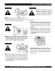
RULES FOR SAFE OPERATION CAUTION: Failure to follow instructions in this manual may lead to serious injury or even death! This equipment is to be operated by trained and qualified personnel only! This equipment is for industrial use only. ■ NEVER touch the hot exhaust manifold, muffler or cylinder. Allow these parts to cool before servicing engine or generator.
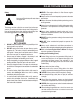
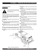
RULES FOR SAFE OPERATION CAUTION CAUTION: CAUTION CAUTION: DO NOT touch or open any of the below mentioned components while the generator is running. Always allow sufficient time for the engine and generator to cool before performing maintenance. ■ NEVER touch output terminals during operation. This is extremely dangerous. Always stop the machine when contact with the output terminals is required. CAUTION CAUTION: Fluid Plugs 1.
RULES FOR SAFE OPERATION ■ NEVER Run engine without air filter. Severe engine damage may occur. Battery CAUTION CAUTION: Never over fill the battery with water above the upper limit. The battery contains acids that can cause injury to the eyes and skin. To avoid eye irritation, always wear safety glasses. Use well insulated gloves when picking up the battery. Use the following guidelines when handling the battery: ■ Always service air cleaner frequently to prevent carburetor malfunction.
RULES FOR SAFE OPERATION Transporting ■ Always shutdown engine before transporting. ■ Tighten fuel tank cap securely. ■ Drain fuel when transporting generator over long distances or rough terrains. ■ Always tie-down the generator during transportation by securing the generator. ■ If generator is mounted on a trailer, make sure trailer complies with all local and state safety transportation laws. See page 10 for basic towing procedures.
DCA-25SSIU — TOWING RULES FOR SAFE OPERATION Towing Safety Precautions CAUTION : Check with your county or state safety towing regulations department before towing your generator. To reduce the possibility of an accident while transporting the generator on public roads, always make sure the trailer (Figure 1) that supports the generator and the towing vehicle are in good operating condition and both units are mechanically sound.
DCA-25SSIU — TRAILER-SAFETY GUIDELINES CAUTION: ALWAYS make sure the trailer is in good operating condition. Check the tires for proper inflation and wear. Also check the wheel lug nuts for proper tightness. Explanation of Chart: This section is intended to provide the user with trailer service and maintenance information. The service and maintenance guidelines referenced in this section apply a wide range of trailers.
DCA-25SSIU — TRAILER-SPECIFICATIONS Table 1. Specifications MODEL APPLICATION FU E L C E LL BRAKE SYSTEM GVWR FRAME LENGTH FRAME WIDTH JACK STAND TRLR-10W SDW225, SGW250,TLW300 NO NO 1900LB S 96" 50" 800LB . FULL TILT WHEEL TRLR-10 DCA10, TLG12, DCA-15 NO NO 1900LB S 96" 50" 800LB . FULL TILT WHEEL TRLR-10XF DCA10, TLG-12, DCA15, TLW-300 52 GAL NO 1900LB S 96" 50" 800LB . FULL TILT WHEEL TRLR-225W WELDERS, D A 7000S S NO NO 2200LB S 85" 42" 800LB .
DCA-25SSIU — TRAILER-SPECIFICATIONS Table 1. Specifications (Con't) MODEL COUPLER TIRES WHEELS AXLE HUBS SUSPENSION ELECTRICAL TRLR-10W 2" B A LL C LA S S 2 ADJUSTABLE 175-13C 13"X4.50" 2200# 2X 2 5 LUG 3 LE A F 4 WIRE LOOM W/ 4 POLE FLAT TRLR-10 2" B A LL C LA S S 2 ADJUSTABLE 175-13C 13"X4.5" 2200#2X 2 5 LUG 3 LE A F 4 POLE FLAT TRLR-10XF 2" B A LL C LA S S 2 ADJUSTABLE 175-13C 13"X4.
DCA-25SSIU — TRAILER SAFETY GUIDELINES Tires/Wheels/Lug Nuts Tires and wheels are a very important and critical components of the trailer. When specifying or replacing the trailer wheels it is important the wheels, tires, and axle are properly matched. CAUTION: DO NOT attempt to repair or modify a wheel. DO NOT install in inner tube to correct a leak through the rim.
DCA-25SSIU — TRAILER SAFETY GUIDELINES Table 3. Suspension Torque Requirements Item Torque (Ft.-Lbs.) 3/8" U-BOLT MIN-30 MAX-35 7/16" U-BOLT MIN-45 MAX-60 1/2" U-BOLT MIN-45 MAX-60 SHACKLE BOLT SNUG FIT ONLY. PARTS MUST ROTATE FREELY. SPRING EYE BOLT LOCKING NUTS OR COTTER PINS ARE PROVIDED TO RETAIN NUT-BOLT ASSEMBLY. MIN-30 MAX-50 SHOULDER TYPE SHACKLE BOLT Lug Nut Torque Requirements It is extremely important to apply and maintain proper wheel mounting torque on the trailer.
DCA-25SSIU — TRAILER-WIRING DIAGRAM NOTE: LIGHTS ARE ORIENTED FROM THE DRIVER’S SEAT PAGE 16 — DCA-25SSIU — PARTS AND OPERATION MANUAL(STD) — REV.
DCA-25SSIU — GENERATOR DECALS The DCA-25SSIU generator is equipped with a number of safety decals. These decals are provided for operator safety and maintenance information. The illustration below and on the preceding pages show the decals as they appear on the machine. Should any of these decals become unreadable, replacements can be obtained from your dealer. PAGE 17 — DCA-25SSIU — PARTS AND OPERATION MANUAL (STD) — REV.
DCA-25SSIU — GENERATOR DECALS PAGE 18 — DCA-25SSIU — PARTS AND OPERATION MANUAL(STD) — REV.
DCA-25SSIU — SPECIFICATIONS Table 5. Specifications Generator Specifications Model DCA-25SSIU Type Revolving field, self ventilated, open protected type synchronous Armature Connection Star with Neutral Zig Zag Phase 3 Single Standby Output 26.5 KVA (21.2 KW) 15.3KW Prime Output 25 KVA (20 KW) 14.4KW Voltage 240V or 480V 240/120V Frequency 60 Hz Speed 1800 rpm Power Factor 0.8 1 Aux. AC Power Single Phase, 60 Hz Voltage 120 V Output 4.8 KW (2.
DCA-25SSIU — GENERAL INFORMATION DCA-25SSIU FAMILIARIZATION Open Delta Excitation System Generator The DCA-25SSIU generator is equipped with the state of The MQ Power Model DCA-25SSIU is a 20 kW generator the art "Open-Delta" excitation system. The open delta that is designed as a high quality portable (requires a trailer system consist of an electrically independent winding wound for transport) power source for telecom sites, lighting among stationary windings of the AC output section.
DCA-25SSIU — MAJOR COMPONENTS Figure 4. Major Components PAGE 21 — DCA-25SSIU — PARTS AND OPERATION MANUAL (STD) — REV.
DCA-25SSIU — DIMENSIONS (TOP, SIDE AND FRONT) Figure 5. Dimensions PAGE 22 — DCA-25SSIU — PARTS AND OPERATION MANUAL(STD) — REV.
NOTE PAGE PAGE 23 — DCA-25SSIU — PARTS AND OPERATION MANUAL (STD) — REV.
DCA-25SSIU — CONTROL PANEL Figure 6. Control Panel PAGE 24 — DCA-25SSIU — PARTS AND OPERATION MANUAL(STD) — REV.
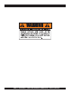
DCA-25SSIU — CONTROL PANEL The definitions below describe the controls and functions of the DCA-25SSIU " Control Panel " (Figure 6). 1. Main Circuit Breaker – This three-pole, 60 Amp main breaker is provided to protect the UNV voltage output terminals from overload. 2. Frequency Meter – Indicates the output frequency in hertz (Hz). Normally 63 Hz ±0.5 Hz . 3. AC Ammeter – Indicates the amount of current the load is drawing from the generator. 4.
DCA-25SSIU — ENGINE OPERATING PANEL Figure 7. Engine Operating Panel PAGE 26 — DCA-25SSIU — PARTS AND OPERATION MANUAL(STD) — REV.
DCA-25SSIU — ENGINE OPERATING PANEL The definitions below describe the controls and functions of the DCA-25SSIU " Engine Operating Panel " (Figure 7). 1. Panel light - Normally used in dark places or at night. When activated, panel will luminate. When the generator is not in use, turn the panel light switch to the ‘OFF’ position. 2. Oil Pressure Lamp - This light will luminate if the oil pressure exceeds 15 psi and will shut off the engine. 3.
DCA-25SSIU — OUTPUT TERMINAL PANEL Output Terminal Panel The output control panel is located on the rear (control panel) end of the generator. The UVW lugs are protected by a face plate cover that can be secured in the close position by a pad lock. Connecting Load Loads can be connected to the generator by the UVW Lugs or the duplex receptacle. (See Figure 9). Make sure to read the operation manual before attempting to connect a load to the generator.
DCA-25SSIU — OUTPUT TERMINAL PANEL NOTE Legs “O” and Ground are considered Bonded Grounds. Figure 10. Output Terminal Description PAGE 29 — DCA-25SSIU — PARTS AND OPERATION MANUAL (STD) — REV.
DCA-25SSIU — OUTPUT AMPERAGE SETUP Output Terminal Panel Available Voltages A wide range of voltages are available to supply load to many different applications. Voltages may be selected by using the voltage selector switch and depending how you hookup your hard wire connection to the generator. To obtain voltages listed, fine adjustment with the voltage regulator on the control panel is necessary. See the table below (Table 6) for a list of available voltages the generator is able to supply.
DCA-25SSIU — OUTPUT AMPERAGE SETUP Receptacle Use When the UVWO terminals are providing power, the receptacle power available decrease. Do not exceed receptacle power available listed on Table 8. Table 8. Receptacle Use Power in Use Receptacle Power Available 240/480V 3-Phase 240/120V Single Phase or Twist Lock CS6369 Duplex NEMA 5-20R 120V 25 14.4 0 20.8 13.2 1.2 16.7 12 2.4 12.5 10.8 3.6 8.4 9.6 4.8 Figure 11. Voltage Selector Switch 240/120V Single Phase Position Figure 12.
DCA-25SSIU — OUTPUT VOLTAGE SETUP 240/120V Hard Wire Hookup 480/240V Hard Wire Hookup With the voltage selector set and locked at ‘single phase 240/120’ and using single phase 120 volts, it will provide two legs available with 60 amps each (Figure 16). When using single phase 240 volts, it will provide one leg with 60 amps available (Figure 16).
DCA-25SSIU — OUTPUT VOLTAGE SETUP Voltage Selector Switch- 3 Phase 480/277V Position The following are additional voltages available when the voltage selector switch is in the 3 phase 480/277V position. Single Phase: 480V, 440V, or 416 Volt This setting can provide single phase power at 480, 440, or 416 volts.
DCA-25SSIU — OUTPUT VOLTAGE SETUP Voltage Selector Switch- 3 Phase 240/139V Position The following are additional voltages available when the voltage selector switch is in the 3 phase 240/139V position. FIGURE 23. Voltage Selector Switch 240/139V Three Phase Position 3 Phase, 240V, 220V, or 208 Volt This setting can provide 3-phase power at 240, 220, or 208 volts.
DCA-25SSIU — OUTPUT VOLTAGE SETUP Voltage Selector Switch- Single Phase 240/120V Position The following are additional voltages available when the 240/120V position. Single Phase: 120 Volt This setting can provide single phase power at 120 volts. After hooking up the hard wires to the lugs as shown in Figure 29, 120 volts can be obtained by using the voltage regulator to fine tune. Figure 29. Hard Wire Hookup for Single Phase, 120 volt Figure 27.
DCA-25SSIU — INSTALLATION Outdoor Installation Install the generator in a location where it will not be exposed to rain or sunshine. Make sure the generator is on secure level ground so that it cannot slide or shift around. Also install the generator in a manner so that the exhaust will not be discharged in the direction of nearby homes. The installation site must be relatively free from moisture and dust. All electrical equipment should be protected from excessive moisture.
DCA-25SSIU — INSTALLATION Figure 30. Typical Generator Grounding Application PAGE 37 — DCA-25SSIU — PARTS AND OPERATION MANUAL (STD) — REV.
DCA-25SSIU — PRE-SETUP General Inspection Prior to Operation Circuit Breakers The DCA-25SSIU generator has been thoroughly inspected and accepted prior to shipment from the factory. However, be sure to check for damaged parts or components, or loose nuts and bolts, which could have occurred in transit. To protect the generator from an overload, a 3-pole, 60 amp, main circuit breaker is provided to protect the UVW output terminals from overload.
DCA-25SSIU — PRE-SETUP Lubrication Oil Fuel Fill the engine crankcase with lubricating oil through the filler hole, but do not overfill. Make sure the generator is level. With the dipstick inserted all the way, verify that the oil level is maintained between the two notches (Figure 31) on the dipstick. See Table 10 for proper selection of engine oil. Use only CC grade or higher. Fill the fuel tank with clean and fresh diesel fuel. DO NOT fill the tank beyond capacity.
DCA-25SSIU — PRE-SETUP CAUTION : When adding coolant or antifreeze to the radiator, do not remove the radiator cap until the unit has completely cooled. Day-to-day addition of coolant is done from the reserve tank. When adding coolant to the radiator, DO NOT remove the radiator cap until the unit has completely cooled. See Table11. for engine, radiator, and reserve tank coolant capacities. Make sure the coolant level in the reserve tank is always between the "H" and the "L" markings. Table 11.
DCA-25SSIU — PRE-SETUP Battery This unit is of negative ground. DO NOT connect in reverse. Always maintain battery fluid level between the specified marks. Battery life will be shortened, if the fluid level is not properly maintained. Add only distilled water when replenishment is necessary. DO NOT over fill. The battery is sufficiently charged if the specific gravity of the battery fluid is 1.28 (at 68° F). If the specific gravity should fall to 1.
DCA-25SSIU — LOAD APPLICATION Single Phase Load CAUTION CAUTION: Always be sure to check the nameplate on the generator and equipment to insure the wattage, amperage and frequency requirements are satisfactorily supplied by the generator for operating the equipment. Motors and motor-driven equipment draw much greater current for starting than during operation. Generally, the wattage listed on the nameplate of the equipment is its rated output.
DCA-25SSIU — GENERATOR START-UP PROCEDURE WARNING: The engine's exhaust contains harmful emissions. ALWAYS ventilate the exhaust when operating inside tunnels, excavations or buildings. Direct exhaust away from nearby personnel. 2. Connect the load to the UVW terminals as shown in Figure 35. These terminals can be found on the output terminal panel, (see page 29 Figure10). To gain access to the output terminals lift the UVW cover. Tighten terminal nuts securely to prevent load wires from slipping out.
DCA-25SSIU — GENERATOR START-UP PROCEDURE 4. Close all engine enclosure doors (Figure 37). 8. Once the preheat indicator lights, turn the ignition key to ‘START’ until the engine starts (Figure 41). Then release the key to ‘RUN’. Figure 41. Ignition Switch ‘START’ Figure 37. Engine Enclosure Doors 5. Check the voltage selection switch (Figure 38) is at the desired voltage. 9. Pull the engine throttle and turn to the right until the metal stop rests against the control panel (Figure 42). Figure 42.
DCA-25SSIU — GENERATOR START-UP PROCEDURE 15. The charging ammeter will dindicate if the battery is being properly charged or if the any current is being charged properly. Figure 45. Voltage Adjust Control Knob 12. The ammeter (Figure 46) will indicate zero amps with no Figure 49. Charging Ammeter load applied. When a load is applied, this meter will indicate the amount of current that the load is drawing 16. The tachometer (Figure 50) will indicate the speed of from the generator’s alternator.
DCA-25SSIU — GENERATOR SHUTDOWN PROCEDURE 18. Observe the generator's ammeter (Figure 52) and verify ENGINE SHUTDOWN it reads the anticipated amount of current with respect To shutdown the generator, use the following procedure: to the load. The ammeter will only display a current reading if the load is in use. 1. Switch both the MAIN, GFCI and LOAD circuit breakers (Figure 53) to the “OFF” position. 40 20 60 0 75 A Figure 52. Ammeter (Load) Figure 53. Main, GFCI and Load circuit breakers 19.
NOTE PAGE PAGE 47 — DCA-25SSIU — PARTS AND OPERATION MANUAL (STD) — REV.
DCA-25SSIU — MAINTENANCE General Inspection Check Oil Level Prior to each use, the generator should be cleaned and inspected for deficiencies. Check for loose, missing or damaged nuts, bolts or other fasteners. Also check for fuel, oil, and coolant leaks. Engine Side (Refer to the Engine Instruction Manual) Check the crankcase oil level prior to each use, or when the fuel tank is filled. Insufficient oil may cause severe damage to the engine. Make sure the generator is level.
DCA-25SSIU — MAINTENANCE Generator Storage For storage of the generator for over 30 days, the following is required: Drain the fuel tank completely. Completely drain the oil from the crankcase and refill with fresh oil. Clean all external parts of the generator with a cloth. Cover the generating set and store in a clean, dry place.
DCA-25SSIU — GENERATOR WIRING DIAGRAM PAGE 50 — DCA-25SSIU — PARTS AND OPERATION MANUAL(STD) — REV.
DCA-25SSIU — ENGINE WIRING DIAGRAM PAGE 51 — DCA-25SSIU — PARTS AND OPERATION MANUAL (STD) — REV.
DCA-25SSIU — TROUBLESHOOTING (ENGINE) Practically all breakdowns can be prevented by proper handling and maintenance inspections, but in the event of a breakdown, use the tables shown for diagnosis based on the Engine Troubleshooting (Table 14). If the problem cannot be remedied, consult our company's business office or service plant. TABLE 14. ENGINE TROUBLESHOOTING SYMPTOM Engine does not start. POSSIBLE PROBLEM SOLUTION No fuel? Replenish fuel. Air in the fuel system? Bleed system.
DCA-25SSIU — TROUBLESHOOTING (ENGINE) TABLE 14. ENGINE TROUBLESHOOTING (CONTINUED) SYMPTOM Engine revolution is not smooth. Either white or blue exhaust gas is observed. Either black or dark gray exhaust gas is observed. Deficient output. POSSIBLE PROBLEM SOLUTION Fuel filter clogged or dirty? Clean or change. Air cleaner clogged? Clean or change. Fuel leak due to loose injection pipe retaining nut? Tighten nut. Injection pump malfunctioning? Repair or replace.
DCA-25SSIU — TROUBLESHOOTING (GENERATOR/ENGINE) Practically all breakdowns can be prevented by proper handling and maintenance inspections, but in the event of a breakdown, use the tables shown for diagnosis based on the Engine and Radiator Troubleshooting (Table15). If the problem cannot be remedied, consult our company's business office or service plant. TABLE 15. GENERATOR TROUBLESHOOTING SYMPTOM POSSIBLE PROBLEM SOLUTION AC Voltmeter defective? Check output voltage using a voltmeter.
NOTE PAGE PAGE 55 — DCA-25SSIU — PARTS AND OPERATION MANUAL (STD) — REV.
EXPLANATION OF CODE IN REMARKS COLUMN The following section explains the different symbols and remarks used in the Parts section of this manual. Use the help numbers found on the back page of the manual if there are any questions. NOTICE The contents and part numbers listed in the parts section are subject to change without notice. Multiquip does not guarantee the availability of the parts listed. SAMPLE PARTS LIST NO. 1 2% 2% 3 4 PART NO. PART NAME QTY. REMARKS 12345 BOLT......................1 .....
DCA-25SSIU — SUGGESTED SPARE PARTS DCA-25SSIU W/ISUZU C240 DIESEL ENGINE 1 TO 3 UNITS Qty. P/N Description 10 ............ 0602046356 ............ CIRCUIT BREAKER 20 ............ X132400150 ........... FUEL FILTER 20 ............ 8970246071 ............ OIL FILTER 5 .............. 5136710400 ............ FAN BELT 1 .............. 8943768300 ............ WATER PUMP 2 .............. 9136140430 ............ WATER PUMP GASKET 2 .............. 1823100080 ............ STARTER SWITCH 5 .............. KEYISUZUF ...
DCA-25SSIU --- GENERATOR ASSY. GENERATOR ASSY. PAGE 58 — DCA-25SSIU — PARTS AND OPERATION MANUAL(STD) — REV.
DCA-25SSIU --- GENERATOR ASSY. GENERATOR ASSY. NO. PART NO.
DCA-25SSIU --- CONTROL BOX ASSY. CONTROL BOX ASSY. PAGE 60 — DCA-25SSIU — PARTS AND OPERATION MANUAL(STD) — REV.
DCA-25SSIU --- CONTROL BOX ASSY. CONTROL BOX ASSY. NO. PART NO. M1246700514 M1246700524 1 M1213000202 M1213000212 M1213000222 2 0601808810 14 15 16 17 18 19 0601808820 021005080 0601842384 0027104010 0601821370 0021004040 0040004000 031104080 0601815925 0027104020 0601823863 0021304015 0601820671 0027105010 0027105015 0601806115 011808015 0601820845 0601820846 M1260600004 0021304015 20 21 22 23 24 0030004000 0027104010 M1213500203 011106015 M1923100004 M1213600104 3 4 5 6 7 8 9 10 11 12 13 ITEM QTY.
DCA-25SSIU --- CONTROL BOX ASSY. CONTROL BOX ASSY. PAGE 62 — DCA-25SSIU — PARTS AND OPERATION MANUAL(STD) — REV.
DCA-25SSIU --- CONTROL BOX ASSY. CONTROL BOX ASSY. NO. PART NO. 25 26 27 28 29 30 31 32 32 33 34 35 36 37 38 39 40 41 42 43 44 45 46 ITEM QTY. REMARKS M1213600114 0027103010 011106015 M1213600004 M1213600014 011106015 SWITCH BRACKET ................................... 1 ......... S/N7102145 MACHINE SCREW 4 HEX. HEAD BOLT ...................................... 4 ......... REPLACES 0016906015 SWITCH COVER ................................................ 1 ........ S/N7100001 TO 7102144 SWITCH COVER ....
DCA-25SSIU ENGINE AND RADIATOR ASSY. ENGINE AND RADIATOR ASSY. PAGE 64 — DCA-25SSIU — PARTS AND OPERATION MANUAL(STD) — REV.
DCA-25SSIU ENGINE AND RADIATOR ASSY. ENGINE AND RADIATOR ASSY. NO. PART NO. ITEM QTY. REMARKS 1 M1923200004A ENGINE .......................................... 1 ........... ISUZU QD60(C240) S/N7100001 TO 7102685 M1925200004 ENGINE .......................................... 1 ........... ISUZU QD60(C240) S/N7102686~ 5136710400 FAN BELT ....................................... 1 ........... REPLACES 0602011401 2 8970246071 CARTRIDGE, OIL FILTER .............. 1 ...........
DCA-25SSIU ENGINE AND RADIATOR ASSY. ENGINE AND RADIATOR ASSY. PAGE 66 — DCA-25SSIU — PARTS AND OPERATION MANUAL(STD) — REV.
DCA-25SSIU ENGINE AND RADIATOR ASSY. ENGINE AND RADIATOR ASSY. NO. PART NO.
DCA-25SSIU --- ENGINE OPERATING PANEL ASSY. ENGINE OPERATING PANEL ASSY. PAGE 68 — DCA-25SSIU — PARTS AND OPERATION MANUAL(STD) — REV.
DCA-25SSIU --- ENGINE OPERATING PANEL ASSY. ENGINE OPERATING PANEL ASSY. NO. PART NO. ITEM 1 2 3 4 5 6 7 8 9 10 11 12 13 14 15 16 17 18 19 20 21 22 23 24 25 26 QTY. REMARKS M1357200102A M1354300304 0601840190 020108060 M1354200004 020108060 0605010503 M1354300204 0602180106 020108060 0207006000 0041206000 1823100080 8944626110 0602120095 0602120480 0602122093 0602122272 WIRE HARNESS, ENGINE 1 SLIDE LEVER 1 KNOB .................................................... 1 ........... REPLACES M9320000004 HEX.
DCA-25SSIU --- OUTPUT TERMINAL ASSY. OUTPUT TERMINAL ASSY. ADD THE FOLLOWING DIGITS AFTER THE PART NUMBER WHEN ORDERING ANY PAINTED PANEL TO INDICATE COLOR OF UNIT: 5 -BLACK 1-ORANGE 6 -CATERPILLAR YELLOW 2-WHITE 3 -SPECTRUM GRAY 7 -CATO GOLD 4 -SUNBELT GREEN 8 -RED THE SERIAL NUMBER MAY BE REQUIRED. PAGE 70 — DCA-25SSIU — PARTS AND OPERATION MANUAL(STD) — REV.
DCA-25SSIU --- OUTPUT TERMINAL ASSY. OUTPUT TERMINAL ASSY. NO. PART NO. ITEM QTY REMARKS 1 8091860103 TERMINAL PANEL ................................... 1 ................... REPLACES M1230700003 2 0801830104A OUTPUT TERMINAL BOLT ..................... 5 ................... REPLACES M922000004 3 0801832204 TIE BOLT ................................................. 5 ................... REPLACES M9220000104 4 0039308000 HEX. NUT 10 5 0040008000 LOCK WASHER 15 6 0041408000 PLAIN WASHER 20 7 011606025 HEX.
DCA-25SSIU --- BATTERY ASSY. BATTERY ASSY. S/N7100001 TO 7100050 S/N7100051~ PAGE 72 — DCA-25SSIU — PARTS AND OPERATION MANUAL(STD) — REV.
DCA-25SSIU --- BATTERY ASSY. BATTERY ASSY. NO. PART NO. 1 2 3 4 5 6 7 8 0602220185 M9310500014 M9103000304 M0602220920 0037808000 0040008000 0040006000 031108160 10 0602220310 M134640004 0602220311 M1346400104 M2346400104 M1346400004 11 M1346400104 12 0016910020 0040510000 9 ITEM QTY. REMARKS BATTERY ....................................... 1 ........... 427MF BATTERY SHEET 1 BATTERY BAND 1 BATTERY BOLT SET ..................... 2 ........... BHL10J;REPLACES M9103200004 WING NUT .................
DCA-25SSIU --- MUFFLER ASSY. MUFFLER ASSY. S/N7100001 TO S/N7105049 S/N7105050~ PAGE 74 — DCA-25SSIU — PARTS AND OPERATION MANUAL(STD) — REV.
DCA-25SSIU --- MUFFLER ASSY. MUFFLER ASSY. NO. PART NO. 1 1 2 3 0602300160 0602300390 M133040004 011008020 3 4 5 011008020 M1330400104 020108060 031108160 6 7 8 9 10 11 12 13 14 15 16 17 M1333000703 M1333000803 8943811610 M1333200004 M1333200014 9098400850 0040010000 0016908035 M1333000604 0602325021 M1330400204 011106015 0602325020 011008020 ITEM QTY. REMARKS MUFFLER;MAM060249 ................. 1 ........... S/N7100001 TO 7105049 MUFFLER ...................................... 1 ...........
DCA-25SSIU --- FUEL TANK ASSY. FUEL TANK ASSY. ADD THE FOLLOWING DIGITS AFTER THE PART NUMBER WHEN ORDERING ANY PAINTED PANEL TO INDICATE COLOR OF UNIT: 5 -BLACK 1-ORANGE 6 -CATERPILLAR YELLOW 2-WHITE 3 -SPECTRUM GRAY 7 -CATO GOLD 4 -SUNBELT GREEN 8 -RED THE SERIAL NUMBER MAY BE REQUIRED. PAGE 76 — DCA-25SSIU — PARTS AND OPERATION MANUAL(STD) — REV.
DCA-25SSIU --- FUEL TANK ASSY. FUEL TANK ASSY. NO. PART NO. 1 M1363000202 2 0605505070 3 M1363200004 4 M9310500104 5 011008020 6 00379080000 7 8 9 10 11 12 13 14 15 16 17 18 19 20 21 22 23 24 25 ITEM QTY. REMARKS FUEL TANK 1 CAP, FUEL TANK 1 TANK BAND 2 SUPPORTER SHEET 4 HEX. HEAD BOLT .......................... 2 ........... REPLACES 0016908020 HEX. NUT ...................................... 2 ........... S/N7100001 TO S/N7101449; REPLACES 0037908000 0207308000 HEX. NUT ..................................
DCA-25SSIU --- ENCLOSURE ASSY. ENCLOSURE ASSY. ADD THE FOLLOWING DIGITS AFTER THE PART NUMBER WHEN ORDERING ANY PAINTED PANEL TO INDICATE COLOR OF UNIT: 5 -BLACK 1-ORANGE 6 -CATERPILLAR YELLOW 2-WHITE 3 -SPECTRUM GRAY 7 -CATO GOLD 4 -SUNBELT GREEN 8 -RED THE SERIAL NUMBER MAY BE REQUIRED. PAGE 78 — DCA-25SSIU — PARTS AND OPERATION MANUAL(STD) — REV.
DCA-25SSIU --- ENCLOSURE ASSY. ENCLOSURE ASSY. NO. PART NO.
DCA-25SSIU --- ENCLOSURE ASSY. ENCLOSURE ASSY. ADD THE FOLLOWING DIGITS AFTER THE PART NUMBER WHEN ORDERING ANY PAINTED PANEL TO INDICATE COLOR OF UNIT: 5 -BLACK 1-ORANGE 6 -CATERPILLAR YELLOW 2-WHITE 3 -SPECTRUM GRAY 7 -CATO GOLD 4 -SUNBELT GREEN 8 -RED THE SERIAL NUMBER MAY BE REQUIRED. PAGE 80 — DCA-25SSIU — PARTS AND OPERATION MANUAL(STD) — REV.
DCA-25SSIU --- ENCLOSURE ASSY. ENCLOSURE ASSY. NO. PART NO.
DCA-25SSIU --- RUBBER SEAL ASSY. RUBBER SEAL ASSY. S/N7100001 TO 7101589 S/N7101590~ PAGE 82 — DCA-25SSIU — PARTS AND OPERATION MANUAL(STD) — REV.
DCA-25SSIU --- RUBBER SEAL ASSY. RUBBER SEAL ASSY. NO. PART NO. ITEM 1 2 3 4 5 6 7 8 9 10 11 12 13 14 15 16 17 18 19 0228910300 0228900725 M1490300004 0228800360 0228900370 0228800605 0229200595 0228900645 0229200750 0229200750 0229200740 0228800670 0228800445 0228800485 0228100568 0228100458 0228100170 0228100171 0228100351 0228100285 0228100153 0228100180 QTY. REMARKS RUBBER SEAL 2 RUBBER SEAL 4 RUBBER SEAL 1 RUBBER SEAL 1 RUBBER SEAL 1 RUBBER SEAL 2 RUBBER SEAL 1 RUBBER SEAL 1 RUBBER SEAL ...........
DCA-25SSIU --- DECALS DECAL ASSY. PAGE 84 — DCA-25SSIU — PARTS AND OPERATION MANUAL(STD) — REV.
DCA-25SSIU --- DECALS DECAL ASSY. NO. PART NO.
ISUZU C240 --- CYLINDER HEAD AND COVER ASSY. CYLINDER HEAD AND COVER ASSY. PAGE 86 — DCA-25SSIU — PARTS AND OPERATION MANUAL(STD) — REV.
ISUZU C240 --- CYLINDER HEAD AND COVER ASSY. CYLINDER HEAD AND COVER ASSY. NO. PART NO. ITEM 1 5111102070 CYLINDER HEAD ASSY. 3 1096000051 SEALING CUP, RR FACE D=44 3-1 5111290060 SEALING CUP, LOWER D=16 3-2 5112190080 SEALING CUP, UPPER D=18 3-3 5096000130 SEALING CUP, DRILLED D=12 4 9098605220 PLUG; LOWER CYLINDER HEAD PLATE 7 5117150230 VALVE SEAT INLET INSERT 8 5117110260 VALVE SEAT EXHAUST INSERT 9 5117210160 VALVE INLET HEAD GUIDE 9-1 5117210160 VALVE EXHAUST HEAD GUIDE 11 5111501080 HOT PLUG ASSY.
ISUZU C240 --- CYLINDER BLOCK ASSY. CYLINDER BLOCK ASSY. PAGE 88 — DCA-25SSIU — PARTS AND OPERATION MANUAL(STD) — REV.
ISUZU C240 --- CYLINDER BLOCK ASSY. CYLINDER BLOCK ASSY. NO. PART NO.
ISUZU C240 ---TIMING GEAR ASSY. TIMING GEAR ASSY. PAGE 90 — DCA-25SSIU — PARTS AND OPERATION MANUAL(STD) — REV.
ISUZU C240 --- TIMING GEAR ASSY. TIMING GEAR ASSY. NO. PART NO. 1 5113110282 2 9113211480 3 9099206010 4 901906140 8 9113120460 9 5096250790 12 9113270450 14 9113120340 17 9019108320 ITEM TIMING GEAR CASE GEAR CASE COVER PACKING BOLT PACKING OIL SEAL POINTER PACKING BOLT QTY. 1 1 1 4 2 1 1 1 9 REMARKS PAGE 91 — DCA-25SSIU — PARTS AND OPERATION MANUAL (STD) — REV.
ISUZU C240 FLYWHEEL HOUSING ASSY. FLYWHEEL HOUSING ASSY. PAGE 92 — DCA-25SSIU — PARTS AND OPERATION MANUAL(STD) — REV.
ISUZU C240 FLYWHEEL HOUSING ASSY. FLYWHEEL HOUSING NO. PART NO. 1-5 5113410191 11 9113430391 12 9019006120 21 5113490380 22 5113490370 23 9019110200 23-1 9019110180 31 9019310450 41 9019110350 41 9010560400 42 9091104100 46 9091505100 ASSY. ITEM FLYWHEEL HOUSING COVER BOLT STIFFENER; RIGHT SIDE STIFFENER; LEFT SIDE BOLT BOLT BOLT BOLT BOLT NUT LOCK WASHER QTY. 1 1 6 1 1 2 2 4 3 1 2 2 REMARKS PAGE 93 — DCA-25SSIU — PARTS AND OPERATION MANUAL (STD) — REV.
ISUZU C240 OIL PAN ASSY. OIL PAN ASSY. PAGE 94 — DCA-25SSIU — PARTS AND OPERATION MANUAL(STD) — REV.
ISUZU C240 OIL PAN ASSY. OIL PAN ASSY. NO. PART NO. 1-2 5113601832 3* 5096050050 3-1 9992023200 4-1* 9097205600 6 9112150810 17 5113670040 24 9992023160 26 9095714160 29 9019106160 31 9112193160 32 9030906160 36 9117606090 42 9019008220 42-1 9019708450 51 5117400870 52# 5117410100 53# 5117500021 56 9099207080 57 9019008200 ITEM QTY. REMARKS OIL PAN ASSY. ................................ 1 ................ INCL.
ISUZU C240 ---OIL PUMP ASSY. OIL PUMP ASSY. PAGE 96 — DCA-25SSIU — PARTS AND OPERATION MANUAL(STD) — REV.
ISUZU C240 ---OIL PUMP ASSY. OIL PUMP ASSY. NO. PART NO. ITEM 1 6* 8*# 11*# 12* 13* 14* 15* 16* 21* 22*% 41 OIL PUMP ASSY. ................................. 1 ........... INCL. ITEMS W/* ROTOR SET .......................................... 1 ........... INCL. ITEMS W/# PIN 1 PIN 1 PINION 1 COVER 1 BOLT 4 LOCK WASHER 4 LOCK WASHER 4 OIL STRAINER ASSY. .......................... 1 ........... INCL.
ISUZU C240 --- CRANKSHAFT, BRIDGE AND FLYWHEEL ASSY. CRANKSHAFT, BRIDGE AND FLYWHEEL ASSY. PAGE 98 — DCA-25SSIU — PARTS AND OPERATION MANUAL(STD) — REV.
ISUZU C240 --- CRANKSHAFT, BRIDGE AND FLYWHEEL ASSY. CRANKSHAFT, BRIDGE AND FLYWHEEL ASSY. NO. PART NO. ITEM QTY REMARKS 1 5115100211 CRANK BEARING KIT;STD 1 1-1 5115300211 CRANK BEARING KIT;-0.25 1 1-2 5115400211 CRANK BEARING KIT;-0.50 1 2 9115810570 THRUST BEARING 2 3 5121112020 PISTON;STD 4 4 5121210070 PISTON RING SET;STD 4 6 5122110090 PISTON PIN 4 7 5095870010 SNAP RING 8 8-1 5122300390 CONNECTING ROD ASSY. .................... 4 ..................... INCL.
ISUZU C240 --- OIL AND FUEL FILTER ASSY. OIL AND FUEL FILTER ASSY. PAGE 100 — DCA-25SSIU — PARTS AND OPERATION MANUAL(STD) — REV.
ISUZU C240 --- OIL AND FUEL FILTER ASSY. OIL AND FUEL FILTER NO. PART NO.
ISUZU C240 --- OIL PIPE ASSY. OIL PIPE ASSY. PAGE 102 — DCA-25SSIU — PARTS AND OPERATION MANUAL(STD) — REV.
ISUZU C240 --- OIL PIPE ASSY. OIL PIPE ASSY. NO. PART NO. 1 9133119810 2 5133111141 3 9099061051 4 9099209000 9 5133111740 10 5096750220 11 9095720080 13 901906120 ITEM OIL PUMP ASSY. ROCKER OIL FEED PIPE BOLT PACKING OIL INJECTION PIPE ADAPTER PACKING BOLT QTY. 1 1 1 2 1 1 2 1 REMARKS PAGE 103 — DCA-25SSIU — PARTS AND OPERATION MANUAL (STD) — REV.
ISUZU C240 --- WATER PUMP AND FAN ASSY. WATER PUMP AND FAN ASSY. PAGE 104 — DCA-25SSIU — PARTS AND OPERATION MANUAL(STD) — REV.
ISUZU C240 --- WATER PUMP AND FAN ASSY. WATER PUMP AND FAN ASSY. NO. PART NO. ITEM QTY. REMARKS 1 5136101673 WATER PUMP ASSY. ................... 1 ............ INCL. ITEMS W/* 3* 5878101391 WATER PUMP REPAIR KIT .......... 1 ............ INCL. ITEMS W.# 6*# 5136310080 BEARING UNIT 1 7*# 9136210760 IMPELLER 1 8*# 9136136070 PACKING 1 9*# 8942366870 SEAL UNIT ASSY.
ISUZU C240 --- INTAKE AND EXHAUST MANIFOLD ASSY. INTAKE AND EXHAUST MAINIFOLD ASSY. PAGE 106 — DCA-25SSIU — PARTS AND OPERATION MANUAL(STD) — REV.
ISUZU C240 --- INTAKE AND EXHAUST MANIFOLD ASSY. INTAKE AND EXHAUST MANIFOLD ASSY. NO. PART NO. ITEM 1 3 20 21 30 46 48 49 51 52 66 76 77 78 83 97 9141126954 9041108500 9141416142 5093020020 5141111290 5141460180 9091646080 9091505080 9091104080 5090000870 5143101961 5096370150 9091104080 9091505080 5093600530 5143340780 INLET MANIFOLD INTAKE STUD EXHAUST MANIFOLD EXHAUST STUD INLET PIPE GASKET PLAIN WASHER LOCK WASHER NUT BOLT INTAKE SHUTTER ASSY.
ISUZU C240 --- AIR CLEANER ASSY. AIR CLEANER ASSY. PAGE 108 — DCA-25SSIU — PARTS AND OPERATION MANUAL(STD) — REV.
ISUZU C240 --- AIR CLEANER ASSY. AIR CLEANER ASSY. NO. PART NO. 3 5142102130 5* 5142150140 27* 5142110670 38* 9142191410 59* 5142120560 76* 5142170040 81* 9142170620 82*# 9142191770 200 9142176020 ITEM QTY. REMARKS AIR CLEANER ASSY. ................... 1 ............ INCL. ITEMS W/* ELEMENT 1 COVER 1 INDICATOR 1 DUST W/BAFFLE PAN 1 CLAMP 1 BOLT W/GASKET WASHER ......... 1 ............ INCL. ITEMS W/# GASKET WASHER 3 BAND ASSY. W/BOLT 2 PAGE 109 — DCA-25SSIU — PARTS AND OPERATION MANUAL (STD) — REV.
ISUZU C240 --- ENGINE FOOT ASSY. ENGINE FOOT ASSY. PAGE 110 — DCA-25SSIU — PARTS AND OPERATION MANUAL(STD) — REV.
ISUZU C240 --- ENGINE FOOT ASSY. ENGINE FOOT ASSY. NO. PART NO.
ISUZU C240 --- INJECTION PUMP ASSY. INJECTION PUMP ASSY. PAGE 112 — DCA-25SSIU — PARTS AND OPERATION MANUAL(STD) — REV.
ISUZU C240 --- INJECTION PUMP ASSY. INJECTION PUMP ASSY. NO. PART NO. ITEM 5 8943864440 15* 20* 35* 38* 40* 42* 5157201400 8941415340 5157400720 9197510790 9099205760 5125240660 QTY. REMARKS INJECTION PUMP ASSY. .................... 1 ..................... REPLACES 5156010252 INCL. ITEMS W/* GOVERNOR ASSY. 1 FEED PUMP ASSY. 1 AUTOMATIC TIMER 1 INJ. PUMP SPACER BRACKET 1 O RING PACKING 1 INJ. PUMP GEAR 1 PAGE 113 — DCA-25SSIU — PARTS AND OPERATION MANUAL (STD) — REV.
ISUZU C240 --- ELECTRICAL PARTS ELECTRICAL PARTS PAGE 114 — DCA-25SSIU — PARTS AND OPERATION MANUAL(STD) — REV.
ISUZU C240 --- ELECTRICAL PARTS ELECTRICAL PARTS NO. PART NO. 1 2 4 8 12 14 19 20 21 23 30 34 36 38-1 50 51 5811000801 5812003410 9822007640 9822531070 9829317430 9825119780 9825301090 9829513240 9829513250 9829513320 9197326100 5824500140 5825500190 1823100080 1823170070 9091114080 9091505080 ITEM QTY. REMARKS STARTER 1 ALTERNATOR .................................... 1 ......................... UP TO OCT. 1992 ALTERNATOR .................................... 1 ......................... OCT.
ISUZU C240 --- ACCESSORIES ACCESSORIES PAGE 116 — DCA-25SSIU — PARTS AND OPERATION MANUAL(STD) — REV.
ISUZU C240 --- ACCESSORIES ACCESSORIES NO. PART NO. ITEM 50 51* 52* 53* 54* 56* 58* 59* 61* 66 67 91 91-1 DRIVE ASSY. ....................................... 1 ..................... INCL. ITEMS W/* CASE 1 COVER 1 PACKING 1 GEAR 1 GEAR 1 BOLT 4 NIPPLE 1 OIL SEAL 1 BOLT 2 PACKING 1 STOPPER ASSY. 1 CABLE ASSY. 1 5193100060 9193110240 9193110200 9193120060 9193160270 9193160170 9019006160 9090310100 9099243550 9019008220 9099211070 5819000020 5828480360 QTY.
ISUZU C240 ---INJECTION PUMP COMP. ASSY. INJECTION PUMP COMP. ASSY. PAGE 118 — DCA-25SSIU — PARTS AND OPERATION MANUAL(STD) — REV.
ISUZU C240 --- INJECTION PUMP COMP. ASSY. INJECTION PUMP COMP. ASSY. NO. PART NO.
ISUZU C240 --- INJECTION PUMP COMP. ASSY. INJECTION PUMP COMP. ASSY. PAGE 120 — DCA-25SSIU — PARTS AND OPERATION MANUAL(STD) — REV.
ISUZU C240 --- INJECTION PUMP COMP. ASSY. INJECTION PUMP COMP. ASSY. NO. PART NO.
ISUZU C240 --- INJECTION PUMP COMP. ASSY. INJECTION PUMP COMP. ASSY. PAGE 122 — DCA-25SSIU — PARTS AND OPERATION MANUAL(STD) — REV.
ISUZU C240 --- INJECTION PUMP COMP. ASSY. INJECTION PUMP COMP. ASSY. NO. PART NO. ITEM 108* 9812214110 KEY 111* 1156190820 BOLT 113* 1157590010 PACKING 137* 9097060370 BOLT 138* 1096350070 PACKING 150* 9812150780 TAPPET PLUG 162* 9091606100 PLAIN WASHER 163* 9091505100 LOCK WASHER 164* 5156390020 NUT 180* 9197510790 BRACKET 181* 9099205760 O RING PACKING QTY. 1 1 2 1 2 4 4 4 4 1 1 REMARKS PAGE 123 — DCA-25SSIU — PARTS AND OPERATION MANUAL (STD) — REV.
ISUZU C240 ---GOVERNOR COMP. ASSY. GOVERNOR COMP. ASSY. PAGE 124 — DCA-25SSIU — PARTS AND OPERATION MANUAL(STD) — REV.
ISUZU C240 --- GOVERNOR COMP. ASSY. COVERNOR COMP. ASSY. NO. PART NO.
ISUZU C240 --- GOVERNOR COMP. ASSY. GOVERNOR COMP. ASSY. PAGE 126 — DCA-25SSIU — PARTS AND OPERATION MANUAL(STD) — REV.
ISUZU C240 --- GOVERNOR COMP. ASSY. GOVERNOR COMP. ASSY. NO. PART NO. ITEM QTY. REMARKS 83* 9813212200 OIL SEAL 1 84* 9813251730 SHIM ..................................................... 1 ..................... T=0.50 85* 9813250970 SHIM ................................................. A/R ..................... T=0.30 86* 9813253180 PLUG 1 88* 9813250300 KEY 1 89* 9813913070 COLLAR 1 90* 9813254880 WASHER A/R 93* 5157250160 GUIDE LEVER ASSY.
ISUZU C240 --- FEED PUMP COMP. ASSY. FEED PUMP COMP. ASSY. 46 PAGE 128 — DCA-25SSIU — PARTS AND OPERATION MANUAL(STD) — REV.
ISUZU C240 --- FEED PUMP COMP. ASSY. FEED PUMP COMP. ASSY. NO. PART NO. ITEM QTY. REMARKS 5* 5157510120 HOUSING 1 9* 9813512050 PISTON 1 10* 9813513030 SPRING 1 11* 9813550230 PLUG 1 12* 9813550350 GASKET 1 15* 5157540010 TAPPET ASSY. ................................... 1 .......................
ISUZU C240 --- AUTO TIMER COMP. ASSY. AUTO TIMER COMP. ASSY. PAGE 130 — DCA-25SSIU — PARTS AND OPERATION MANUAL(STD) — REV.
ISUZU C240 --- AUTO TIMER COMP. ASSY. AUTO TIMER COMP. ASSY. NO. PART NO.
ISUZU C240 --- NOZZLE HOLDER COMP. ASSY. NOZZLE HOLDER COMP. ASSY. PAGE 132 — DCA-25SSIU — PARTS AND OPERATION MANUAL(STD) — REV.
ISUZU C240 --- NOZZLE HOLDER COMP. ASSY. NOZZLE HOLDER COMP. ASSY. NO. PART NO. ITEM QTY. REMARKS 5%# 5153410020 PUSH ROD 4 7%# 5153430020 SPRING 4 9%# 9153396010 SCREW 4 11%# 5153340030 NUT 4 12%# 9153390560 GASKET 4 13%# 9153390570 WASHER 4 21%# 9153326030 NUT 4 22%# 9153520050 GASKET 4 23%# 9153510070 CONNECTOR 4 31%# 5153490010 BOLT 4 32%# 9095714080 GASKET 8 38%# 9153596010 SCREW 4 39% 5153110060 NOZZLE INJECTOR 4 40% 8941145150 HOLDER ASSY W/O NOZZLE ............ 4 .......................
ISUZU C240 ---STARTER COMP. ASSY. STARTER COMP. ASSY. PAGE 134 — DCA-25SSIU — PARTS AND OPERATION MANUAL(STD) — REV.
ISUZU C240 --- STARTER COMP. ASSY. STARTER COMP. ASSY. NO. PART NO. ITEM QTY. REMARKS 6 5811210160 ARMATURE ASSY. .................................... 1 ................ INCL. ITEMS W/* 13* 5811291050 PINION STOPPER 1 14* 5811290030 WASHER SET 1 22* 5811120100 FIELD COIL ASSY. .................................... 1 ................ INCL. ITEM W/> 25*> 5811160480 BRUSH, + 1 30* 5811150130 REAR COVER ASSY. ................................ 1 ................ INCL.
ISUZU C240 --- ALTERNATOR COMP. ASSY. ALTERNATOR COMP. ASSY. (OCT. 1992~) PAGE 136 — DCA-25SSIU — PARTS AND OPERATION MANUAL(STD) — REV.
ISUZU C240 --- ALTERNATOR COMP. ASSY. ALTERNATOR COMP. ASSY. (OCT. 1992~) NO. PART NO. ITEM 3 4*> 5* 7* 8*# 9*# 10*#% 11*#% 12*#% 13*#% 14*# 17* 18*& 19*& 22*& 23* 24* 26* 27* 5812210630 9000901810 5812110580 5812141310 5812141320 5812190360 5812150460 5812291660 5812150400 5812700040 5812620050 5812130430 5812290290 5098000870 5812291650 5812220760 9822350150 5812291820 5812291830 QTY. REMARKS ROTOR ASSY. ........................................................ 1 ..... INCL.
ISUZU C240 ---ALTERNATOR COMP. ASSY. ALTERNATOR COMP. ASSY. (BEFORE OCT. 1992) PAGE 138 — DCA-25SSIU — PARTS AND OPERATION MANUAL(STD) — REV.
ISUZU C240 --- ALTERNATOR COMP. ASSY. ALTERNATOR COMP. ASSY. (BEFORE OCT. 1992) NO. PART NO. ITEM 5 8* 18* 20* 25* 27*# 30*# 33*# 34*# 35*# 39*# 50* 52*& 53*& 54*& 55*& 75* 80* 90* 91* 5812210100 9000901810 9822250270 5812110090 5812140010 9822316190 5812150010 9822316170 9822316180 9822350700 9822319040 9822313080 9822158230 9822158240 9822159170 9000901820 5812220140 9822350740 9822350720 9822350730 QTY. REMARKS ROTOR ASSY. ....................................................... 1 ..... INCL.
TERMS AND CONDITIONS OF SALE — PARTS PAYMENT TERMS 5. Parts must be in new and resalable condition, in the original Multiquip package (if any), and with Multiquip part numbers clearly marked. 6. The following items are not returnable: Multiquip reserves the right to quote and sell direct to Government agencies, and to Original Equipment Manufacturer accounts who use our products as integral parts of their own products. a. SPECIAL EXPEDITING SERVICE Terms of payment for parts are net 30 days.
NOTES PAGE 141 — DCA-25SSIU — PARTS AND OPERATION MANUAL (STD) — REV.
OPERATION AND PARTS MANUAL HERE’S HOW TO GET HELP PLEASE HAVE THE MODEL AND SERIAL NUMBER ON-HAND WHEN CALLING UNITED STATES Multiquip Corporate Office 18910 Wilmington Ave. Carson, CA 90746 Contact: mq@multiquip.com MQ Parts Department Tel.