PARTS AND OPERATION MANUAL OPERATION AND PARTS MANUAL WHISPERWATTTM SERIES MODEL DCA-56SPX 60 Hz GENERATOR (PARTS LIST NO. B4871301604 S/N 3796699~) Revision #1 (04/14/10) THIS MANUAL MUST ACCOMPANY THE EQUIPMENT AT ALL TIMES.
PROPOSITION 65 WARNING Diesel engine exhaust and some of PAGE 2 — DCA-56SPX— OPERATION AND PARTS MANUAL — REV.
NOTE PAGE 1 DCA-56SPX— OPERATION AND PARTS MANUAL — REV.
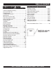
TABLE OF CONTENTS MQ POWER DCA-56SPX WHISPER WATTTM GENERATOR WHISPERW California Proposition 65 Warning ..................................... 2 Here's How To Get Help .................................................... 3 Table Of Contents ............................................................. 4 Parts Ordering Procedures ............................................... 5 Specifications ................................................................... 6 Dimensions (Top, Side, Front) ................
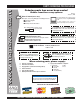
www.mqpower.com PARTS ORDERING PROCEDURES Ordering parts has never been easier! Choose from three easy options: Order via Internet (Dealers Only): Best Deal! Effective: January 1st, 2006 If you have an MQ Account, to obtain a Username and Password, E-mail us at: parts@multiquip. com. Order parts on-line using Multiquip’s SmartEquip website! N View Parts Diagrams N Order Parts N Print Specification Information To obtain an MQ Account, contact your District Sales Manager for more information.
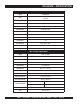
DCA-56SPX — SPECIFICATIONS Table 1. Generator Specifications Model DCA-56SPX Type Revolving field, self ventilated, open protected type synchronous generator Armature Connection Series Phase Single Phase 3-Wire Standby Output 58.8 KW (TBD KVA) Prime Output 56 KW (TBD KVA) Voltage 2 4 0 V /1 2 0 Frequency 60 Hz Speed 1800 r pm Power Factor 1.0 Aux. AC Power Single Phase, 60 Hz Voltage 120 V Output 4.8 KW (2.4 KW x 2) Table 2.
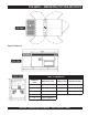
DCA-56SPX — DIMENSIONS (TOP, SIDE AND FRONT) Figure 1. Dimensions TABLE 3. DIMENSIONS Reference Letter Dimension ft. (mm.) Reference Letter Dimension ft. (mm.) A 35.8 in. (910 mm.) F 94.49 in. (2,400 mm.) B 35.8 in. (910 mm.) G 55.12 in. (1,400 mm.) C 29.5 in. (750 mm.) H 35.43 in. (900 mm.) D 35.8 in. (770 mm.) E 29.5 in. (750 mm.) 1 DCA-56SPX— OPERATION AND PARTS MANUAL — REV.
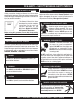
DCA-56SPX — SAFETY MESSAGE ALERT SYMBOLS FOR YOUR SAFETY AND THE SAFETY OF OTHERS! Safety precautions should be followed at all times when operating this equipment. Failure to read and understand the Safety Messages and Operating Instructions could result in injury to yourself and others. NOTE This Owner's Manual has been developed to provide complete instructions for the safe and efficient operation of the MQ Power Model DCA-56SPX Whisperwatt™ Generator.
DCA-56SPX — SAFETY MESSAGE ALERT SYMBOLS WARNING - ROTATING PARTS NEVER operate equipment with covers, or guards removed. Keep fingers, hands, hair and clothing away from all moving parts to prevent injury. CAUTION - ACCIDENTAL STARTING ALWAYS place the engine ON/OFF switch (MPEC) in the OFF/RESET position when the generator is not in use. CAUTION - OVER-SPEED CONDITIONS NEVER tamper with the factory settings of the engine governor or settings.
DCA-56SPX — RULES FOR SAFE OPERATION DANGER - READ THIS MANUAL! Failure to follow instructions in this manual may lead to serious injury or even DEATH! This equipment is to be operated by trained and qualified personnel only! This equipment is for industrial use only. The following safety guidelines should always be used when operating the DCA-56SPX Whisperwatt™ AC Generator. ■ NEVER use accessories or attachments, which are not recommended by Multiquip for this equipment.
DCA-56SPX — RULES FOR SAFE OPERATION ■ ALWAYS be sure the operator is familiar with proper safety precautions and operation techniques before using generators. NEVER leave the generator unattended, turn off engine when unattended. Unauthorized equipment modifications will void all warranties. ALWAYS ensure generator is on level ground before use. DO NOT place hands or fingers inside generators engine compartment when engine is running. NEVER run engine without air cleaner. Severe engine damage may occur.
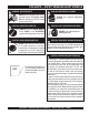
DCA-56SPX — RULES FOR SAFE OPERATION WARNING - BURN HAZARDS To prevent burns, DO NOT touch or open any of the below mentioned components while the engine is running or immediately after operations. Always allow sufficient time for the engine and generator to cool before performing maintenance.
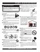
DCA-56SPX — RULES FOR SAFE OPERATION Using a generator indoors CAN KILL YOU IN MINUTES. Generator exhaust contains carbon monoxide. This is a posion you cannot see or smell 20A 2900 120 V OFF GA-2.9R 120V 20A 2900 120V ON OFF AC CIRCUIT BREAKER 20A 2900 120 V GA-2.9R 22A NEVER grab or touch a live power cord with wet hands, the possibility exist of electrical shock, electrocution, and even death! DANGER 120 V ON GA-2.
DCA-56SPX — RULES FOR SAFE OPERATION If your generator is trailer mounted, please read the towing and safety requirements listed below. Towing and Transporting Safety To reduce the possibility of an accident while transporting the generator on public roads, always make sure the trailer that supports the generator and the towing vehicle are in good operating condition and both units are mechanically sound.
NOTE PAGE 1 DCA-56SPX— OPERATION AND PARTS MANUAL — REV.
DCA-56SPX — GENERATOR DECALS The DCA-56SPX generator is equipped with a number of safety decals (Figures 2 and 3). These decals are provided for operator safety and maintenance information. The illustration below and on the preceding page show the decals as they appear on the machine. Should any of these decals become unreadable, replacements can be obtained from your dealer. Figure 2. Generator Decals PAGE 16 — DCA-56SPX— OPERATION AND PARTS MANUAL — REV.
DCA-56SPX — GENERATOR DECALS Figure 3. Generator Decals (Cont inued) DCA-56SPX— OPERATION AND PARTS MANUAL — REV.
DCA-56SPX — INSTALLATION Figure 4. Typical Generator Grounding Application PAGE 18 — DCA-56SPX— OPERATION AND PARTS MANUAL — REV.
DCA-56SPX — INSTALLATION Outdoor Installation Generator Grounding Install the generator in a area that is free of debris, bystanders, and overhead obstructions. Make sure the generator is on secure level ground so that it cannot slide or shift around. Also install the generator in a manner so that the exhaust will not be discharged in the direction of nearby homes. The installation site must be relatively free from moisture and dust. All electrical equipment should be protected from excessive moisture.
DCA-56SPX — GENERAL INFORMATION DCA-56SPX Whisperwatt™ Series Familiarization Generator The MQ Power Model DCA-56SPX is a 56 kW generator (Figure 5) that is designed as a high quality portable (requires a trailer for transport) power source for telecom sites, lighting facilities, power tools, submersible pumps and other industrial and construction machinery.
DCA-56SPX — MAJOR COMPONENTS Table 4. Generator Major Components ITEM NO. Figure 5. Major Components DESCRIPTION 1 Output Terminal Assembly 2 Output Receptacles Assembly 3 Muffler Assembly 4 Air Filter Assembly 5 Battery Assembly 6 Generator Assembly 7 Engine Assembly 8 Fuel Tank Assembly 9 Circuit Breaker Assembly 10 Engine Control Panel Assembly 11 Generator Control Panel Assembly DCA-56SPX— OPERATION AND PARTS MANUAL — REV.
NOTE PAGE PAGE 22 — DCA-56SPX— OPERATION AND PARTS MANUAL — REV.
DCA-56SPX — GENERATOR CONTROL PANEL Figure 6. Generator Control Panel The definitions below describe the controls and functions of the DCA-56SPX Generator Control Panel (Figure 6). 1. Frequency Meter – Indicates the output frequency in hertz (Hz). Normally 60 Hz. 2. 3. 4. 5. 6. Located behind the generator control panel is the Generator Control Box. This box contains some of the necessary electronic components required to make the generator function.
DCA-56SPX — ENGINE OPERATING PANEL 1 3 2 4 5 AUTO MANUAL OFF/RESET 10 LOW OIL PRESSURE HIGH COOLANT TEMPERATURE OVERCRANK OVERSPEED ENGINE RUNNING 6 MOOOOO-20001Q 7 8 9 Figure 7. Engine Operating Panel PAGE 24 — DCA-56SPX— OPERATION AND PARTS MANUAL — REV.
DCA-56SPX — ENGINE OPERATING PANEL The definitions below describe the controls and functions of the DCA-56SPX Engine Operating Panel (Figure 7). 1. Panel Light – Normally used in dark areas or at night time. When activated, panel lights will illuminate. When the generator is not in use be sure to turn the panel light switch to the OFF position. 2. Panel Light Switch – When activated will turn on control panel light. 3.
DCA-56SPX — OUTPUT TERMINAL PANEL FAMILIARIZATION Output Terminal Panel The Output Terminal Panel (Figure 8) shown below is located on the right-hand side (left from control panel) of the generator. Lift up on the cover to gain access to receptacles and terminal lugs.
DCA-56SPX — OUTPUT TERMINAL PANEL FAMILIARIZATION 100 VAC GFCI Receptacles There are two 120 VAC, 20 amp GFCI (Duplex Nema 5-20R) recepacles provided on the output terminal panel. These receptacles can be accessed in any voltage selector switch position. Each receptacle is protected by a 20 amp circuit breaker. These breakers are located directly above the GFCI receptacles.
DCA-56SPX — OUTPUT TERMINAL PANEL FAMILIARIZATION Over Current Relay Loads can be connected to the generator by the Ouput An over current relay (Figure 14) is connected to the main Terminal Lugs or the convenience receptacles (Figure 13). circuit breaker. In the event of an overload, both the circuit Make sure to read the operation manual before attempting breaker and the over current relay may trip. If the circuit breaker can not be reset, the reset button on the over curto connect a load to the generator.
DCA-56SPX — LOAD APPLICATION/MAXIMUM AMPERAGE Single Phase Load Always be sure to check the nameplate on the generator and equipment to insure the wattage, amperage, frequency, and voltage requirements are satisfactorily supplied by the generator for operating the equipment. Generally, the wattage listed on the nameplate of the equipment is its rated output.
DCA-56SPX — GAUGE READING/ TERMINAL PANEL CONNECTIONS How to Read the Output Terminal Gauges. The gauges on the control panel are provided to help observe how much power is being supplied at the Output terminals lugs. Reading Amperage To determine the amperage at a terminal lug, set the AC Ammeter Change-Over Switch to the appropriate setting (Figure 15) to activate the AC Ammeter Gauge (Figure 16) and read the available amperage at the terminal lug.
DCA-56SPX — SETUP Fuel Check Circuit Breakers To protect the generator from an overload, a 3-pole, 90 amp, main circuit breaker is provided to protect the U,O, and V Output Terminals from overload. In addition two single-pole, 20 amp GFCI circuit breakers are provided to protect the GFCI receptacles from overload. Two 50 amp load circuit breakers have also been provided to protect the auxiliary receptacles from overload.
DCA-56SPX — SETUP Refueling Procedure: NOTE WARNING - RESPIRATORY HAZARDS Diesel fuel and its vapors are dangerous to your health and the surrounding environment. Avoid skin contact and/or inhaling fumes. 3. 1. Level Tanks – Make sure fuel cells are level with the ground. Failure to do so will cause fuel to spill from the tank before reaching full capacity (Figure 22). If generator is equipped with an environmental fuel tank, reference Figures 24 and 25.
DCA-56SPX — SETUP Coolant (Antifreeze/Summer Coolant/Water) ISUZU recommends antifreeze/summer coolant for use in their engines, which can be purchased in concentrate (and mixed with 50% demineralized water) or pre-diluted. See the ISUZU Engine Owner's Manual for further details. Cleaning the Radiator The engine may overheat if the radiator fins become overloaded with dust or debris. Periodically clean the radiator fins with compressed air.
DCA-56SPX — SETUP Battery When connecting battery do the following: This unit is of negative ground DO NOT connect in reverse. 1. NEVER connect the battery cables to the battery terminals when the MPEC Control Switch is in either Always maintain battery fluid level between the specified marks. Battery life will be shortened, if the fluid level are not the MANUAL position. ALWAYS make sure that the MPEC Control Switch is in the OFF/RESET position when properly maintained.
DCA-56SPX — GENERATOR START-UP PROCEDURE (MANUAL) Manual Start-up Procedure Before Starting CAUTION - LETHAL EXHAUST HAZARD The engine's exhaust contains harmful emissions. ALWAYS have adequate ventilation when operating. Direct exhaust away from nearby personnel. 1. Place the MPEC Control Switch in the MANUAL position to start the engine (Figure 30). WARNING - STARTING THE GENERATOR NEVER! manually start the engine with the main, GFCI or auxiliary circuit breakers in the ON (closed) position.
DCA-56SPX — GENERATOR START-UP PROCEDURE (MANUAL) 6. The generator's AC-voltmeter (Figure 33) will display the generator’s output in VOLTS. If the voltage is not within the specified tolerance, use the voltage adjustment control knob (Figure 34) to increase or decrease the desired voltage. 9. The coolant temperature gauge (Figure 37) will indicate the coolant temperature. Under normal operating conditions the coolant temperature should be between 180~221 °F (82~105 °C), Green Zone. Figure 37.
DCA-56SPX — GENERATOR START-UP PROCEDURE (AUTO MODE) When starting generator in AUTO mode use the "Manual Start-up" procedure except where noted (see below). Starting (Auto Mode) DANGER - ELECTRICAL SYSTEM HAZARDS Before connecting this generator to any building’s electrical system, a licensed electrician must install an isolation (transfer) switch. Serious damage to the building’s electrical system may occur without this transfer switch.
DCA-56SPX — GENERATOR SHUT-DOWN PROCEDURES WARNING - SHUTTING DOWN THE GENERATOR NEVER stop the engine suddenly except in an emergency. Normal Shutdown Procedure To shutdown the generator use the following procedure: 1. Place both the MAIN, GFCI and LOAD circuit breakers as shown in Figure 39 to the OFF position. Emergency Shutdown Procedure 1. Place the MPEC Control Switch switch (Figure 42) to the OFF/RESET position. 2.
DCA-56SPX — MAINTENANCE 10 Hrs DAILY TABLE 11.
DCA-56SPX — MAINTENANCE Flushing Out Radiator and Replacing Coolant Air Removal If air enters the fuel injection system of a diesel engine, Open both cocks located at the crankcase side and at the lower part of the radiator and drain coolant. Open the starting becomes impossible. After running out of fuel, or after disassembling the fuel system, bleed the system radiator cap while draining. Remove the overflow tank according to the following procedure. See the VOLVO Engine and drain. Manual for details.
DCA-56SPX — MAINTENANCE Jacket Water Heater and Internal Battery Charger 120 VAC Input Receptacles (OPTIONAL) This generator can be optionally equipped with two 120 VAC, 20 amp input receptacles located on the output terminal panel. The purpose of these receptacles is to provide power via commercial power to the jacket water heater and internal battery charger. These receptacles will ONLY function when commercial power has been supplied to them (Figure 43).
DCA-56SPX — TRAILER MAINTENANCE 8. Tire Size - Indicates the diameter of the tire in inches (10,12,14, etc.), and the width in millimeters This section is intended to provide the user with generic (175,185,205, etc.). The tire diameter must match the trailer service and maintenance information. The service and diameter of the tire rim. maintenance guidelines referenced in this section refer to a wide range of trailers. 9. Tire Ply - The tire ply (layers) number is rated in letters; 2-ply,4-ply,6-ply, etc.
DCA-56SPX — TRAILER MAINTENANCE Brakes Trailer brakes should be inspected the first 200 miles of operation. This will allow the brake shoes and drums to seat properly. After the first 200 mile interval, inspect the brakes every 3,000 miles. If driving over rough terrain, inspect the brakes more frequently. Figure 44 displays the major hydraulic surge brake components that will require inspection and maintenance.
DCA-56SPX — TRAILER MAINTENANCE Tires/Wheels/Lug Nuts Tires and wheels are a very important and critical components of the trailer. When specifying or replacing the trailer wheels it is important the wheels, tires, and axle are properly matched. CAUTION - EYESIGHT HAZARD Suspension The leaf suspension springs and associated components (Figure 45) should be visually inspected every 6,000 miles for signs of excessive wear, elongation of bolt holes, and loosening of fasteners.
DCA-56SPX — TRAILER MAINTENANCE Lug Nut Torque Requirements It is extremely important to apply and maintain proper wheel mounting torque on the trailer. Be sure to use only the fasteners matched to the cone angle of the wheel. Proper procedure for attachment of the wheels is as follows: 1. Start all wheel lug nuts by hand. 2. Torque all lug nuts in sequence (see Figure 46). DO NOT torque the wheel lug nuts all the way down. Tighten each lug nut in 3 separate passes as defined by Table 15. 3.
DCA-56SPX — TRAILER WIRING DIAGRAM Figure 47. Trailer/Towing Vehicle Wiring Diagram PAGE 46 — DCA-56SPX— OPERATION AND PARTS MANUAL — REV.
DCA-56SPX — GENERATOR WIRING DIAGRAM Figure 48. Generator Wiring Diagram 1 DCA-56SPX— OPERATION AND PARTS MANUAL — REV.
DCA-56SPX — ENGINE WIRING DIAGRAM Figure 49. Engine Wiring Diagram PAGE 48 — DCA-56SPX— OPERATION AND PARTS MANUAL — REV.
DCA-56SPX — TROUBLESHOOTING (ENGINE) Practically all breakdowns can be prevented by proper handling and maintenance inspections, but in the event of a breakdown, use Table 16 shown below for diagnosis of the engine. If the problem cannot be remedied, consult our company's business office or service plant. TABLE 16. ENGINE TROUBLESHOOTING SYMPTOM Engine does not star t. POSSIBLE PROBLEM SOLUTION No fuel? Replenish fuel. Air in the fuel system? Bleed system.
DCA-56SPX — TROUBLESHOOTING (ENGINE) TABLE 16. ENGINE TROUBLESHOOTING (CONTINUED) SYMPTOM POSSIBLE PROBLEM Engine revolution is not smooth. Either white or blue exhaust gas is observed. Either black or dark gray exhaust gas is observed. Deficient output. SOLUTION Fuel filter clogged or dir ty? Clean or change. Air cleaner clogged? Clean or change. Fuel leak due to loose injection pipe retaining nut? Tighten nut. Injection pump malfunctioning? Repair or replace.
DCA-56SPX — TROUBLESHOOTING (GENERATOR) Practically all breakdowns can be prevented by proper handling and maintenance inspections, but in the event of a breakdown, use Table 17 shown below for diagnosis of the generator. If the problem cannot be remedied, consult our company's business office or service plant. TABLE 17.
DCA-56SPX — TROUBLESHOOTING (ENGINE CONTROLLER) Practically all breakdowns can be prevented by proper handling and maintenance inspections, but in the event of a breakdown, use Table 18 (Engine Controller Troubleshooting) as a basic guideline for troubleshooting the Microprocessor Engine Controller unit (MPEC). If the problem cannot be remedied, consult our company's business office or service plant. TABLE 18. ENGINE CONTROLLER TROUBLESHOOTING (MPEC) SYMPTOM POSSIBLE PROBLEM Low oil pressure light is on.
NOTE PAGE 1 DCA-56SPX— OPERATION AND PARTS MANUAL — REV.
DCA-56SPX — EXPLANATION OF CODE IN REMARKS COLUMN The following section explains the different symbols and remarks used in the Parts section of this manual. Use the help numbers found on the back page of the manual if there are any questions. NOTICE The contents and part numbers listed in the parts section are subject to change without notice. Multiquip does not guarantee the availability of the parts listed. SAMPLE PARTS LIST NO. 1 2% 2% 3 4 PART NO. PART NAME QTY. REMARKS 12345 BOLT.....................
DCA-56SPX — SUGGESTED SPARE PARTS DCA-56SPX WHISPER WATTGENRATOR W/ISUZU FF-4BGIT DIESEL ENGINE 1 TO 3 UNITS Qty. P/N Description 1 ......... B5310500003 ..... HOSE, RADIATOR UPPER 1 ......... B5310500103 ..... HOSE, RADIATOR LOWER 1 ......... 0845500104 ....... FUEL CAP 1 ......... 0602122272 ....... UNIT, OIL PRESSURE 1 ......... 0602123260 ....... UNIT, WATER TEMPERATURE 6 ......... 1132400791 ....... FILTER, FUEL CARTRIDGE 6 ......... 1132402321 ....... FILTER, OIL CARTRIDGE 3 ......... 0602046365 .....
DCA-56SPX — GENERATOR ASSY. GENERATOR ASSY. PAGE 56 — DCA-56SPX— OPERATION AND PARTS MANUAL — REV.
DCA-56SPX — GENERATOR ASSY. GENERATOR ASSY. NO. 1 1-1 1-2 1-3 1-4 1-5 1-6 1-7 1-8 1-9 1-10 1-11 1-12 1-14 1-15 1-16 1-17 2 3 4 5 6 7 8 9 10 11 12 13 14 15 16 17 18 19 20 21 22 23 24 25 26 27 28 29 29A 29B 30 PART NO.
DCA-56SPX— CONTROL BOX ASSY. CONTROL BOX ASSY. (S/N 7800001~7800129) PAGE 58 — DCA-56SPX— OPERATION AND PARTS MANUAL — REV.
DCA-56SPX— CONTROL BOX ASSY. CONTROL BOX ASSY. NO. 1 2-1 2-2 3 4 5 6 7 8 9 10 11 12 13 14 15 16 17 18 19 20 21 22 23 24 25 26 27 27A 27B 28 29 30 31 32 33 34 35 35A 36 37 38 39 PART NO.
DCA-56SPX— CONTROL BOX ASSY. CONTROL BOX ASSY. (S/N 7800001~7800129) PAGE 60 — DCA-56SPX— OPERATION AND PARTS MANUAL — REV.
DCA-56SPX— CONTROL BOX ASSY. CONTROL BOX ASSY. NO. 40 41 42 43 44 45 46 47 48 49 50 51 52 52A 53 54 55 56 57 58 59 60 61 62 PART NO. 060180271 0601840073 0601840121 B5223100004 0027105010 0027105010 0845056404 0041208000 0080200007 B5351100804 0602202545 0601831340 0021004040 0207004000 0602202506 0602120095 0602122093 0602123090 0602121080 0602125090 0601810141 0601831330 0601831585 0601802149 PART NAME QTY.
DCA-56SPX— ENGINE AND RADIATOR ASSY. ENGINE AND RADIATOR ASSY. PAGE 62 — DCA-56SPX— OPERATION AND PARTS MANUAL — REV.
DCA-56SPX— ENGINE AND RADIATOR ASSY. ENGINE & RADIATOR ASSY. NO. 1 1-1 1-2 2 3 4 5 6 7 8 9 10 11 11-1 11-2 12 13 14 15 16 17 18 19 20 21 22 23 24 25 25A 26 27 28 29 30 31 32 33 34 35 36 37 38 PART NO.
DCA-56SPX— ENGINE AND RADIATOR ASSY. ENGINE & RADIATOR ASSY. PAGE 64 — DCA-56SPX— OPERATION AND PARTS MANUAL — REV.
DCA-56SPX— ENGINE AND RADIATOR ASSY. ENGINE AND RADIATOR ASSY. NO. 39 40 41 42 43 44 45 46 47 48 49 50 51 PART NO. 0605511395 0603306395 0602021070 0269200500 0845031303 0802081104 0199900400 0199900175 0193601800 0605515106 B5316100204 0017108020 8972333820 PART NAME QTY. REMARKS VALVE 1 HOSE JOINT 1 CAP 1 DRAIN HOSE 1 RESERVE TANK 1 RESEREVE TANK CAP 1 HOSE 1 HOSE 1 HOSE 1 HOSE BAND 3 RESERVE TANK BRACKET 1 HEX HEAD BOLT 2 FAN BELT.................................................. 1 .........
DCA-56SPX— OUTPUT TERMINAL ASSY. OUTPUT TERMINAL ASSY. PAGE 66 — DCA-56SPX— OPERATION AND PARTS MANUAL — REV.
DCA-56SPX— OUTPUT TERMINAL ASSY. OUTPUT TERMINAL ASSY. NO. 1 2 3 4 5 6 7 8 9 10 11 11A 11B 12 12A 13 14 15 16 17 18 19 20 20-1 21 22 23 24 24A 25 26 27 28 29 30 31 32 33 34 35 PART NO.
DCA-56SPX— ACTUATOR ASSY. ENGINE OPERATING PANEL ASSY. PAGE 68 — DCA-56SPX— OPERATION AND PARTS MANUAL — REV.
DCA-56SPX— ACTUATOR ASSY. ACTUATOR ASSY. NO. 1 1-1 2 3 3A 3B 4 5 6 7 8 9 10 11 12 13 14 15 16 17 18 PART NO.
DCA-56SPX— BATTERY ASSY. BATTERY ASSY. PAGE 70 — DCA-56SPX— OPERATION AND PARTS MANUAL — REV.
DCA-56SPX— BATTERY ASSY. BATTERY ASSY. NO. 1 2 3 4 5 6 7 8 9 10 11 12 13 14 15 16 17 18 19 PART NO.
DCA-56SPX— MUFFLER ASSY. MUFFLER ASSY. PAGE 72 — DCA-56SPX— OPERATION AND PARTS MANUAL — REV.
DCA-56SPX— MUFFLER ASSY. MUFFLER ASSY. NO. 1 2 3 4 5 6 7 8 9 10 11 12 PART NO. B5330100303 0016910025 B5333000203 0602320101 B5333200004 0039308000 0016908040 8102354004 B5332300004 0016908020 0603320116 0030008000 PART NAME QTY. REMARKS MUFFLER 1 HEX HEAD BOLT 4 EXHAUST PIPE 1 GASKET ................................................... 1 .........
DCA-56SPX— FUEL TANK ASSY. FUEL TANK ASSY. PAGE 74 — DCA-56SPX— OPERATION AND PARTS MANUAL — REV.
DCA-56SPX— FUEL TANK ASSY. FUEL TANK ASSY. NO. 1 1-1 1-2 2 2A 3 4 5 6 7 8-1 8-2 8-3 9 10 11 12 13 14 15 16 17 PART NO.
DCA-56SPX— ENCLOSURE ASSY. ENCLOSURE ASSY. PAGE 76 — DCA-56SPX— OPERATION AND PARTS MANUAL — REV.
DCA-56SPX— ENCLOSURE ASSY. ENCLOSURE ASSY. NO. 1 2 3 4 4A 5 6 6A 7 8 9 10 11 12 12A 12B 13 14 14A 15 16 16A 17 17A 18 19 20 21 22 22A 23 24 24A 25 26 27 28 29 29A 30 31 32 33 PART NO.
DCA-56SPX— ENCLOSURE ASSY. (CONT.) ENCLOSURE ASSY. (CONT.) PAGE 78 — DCA-56SPX— OPERATION AND PARTS MANUAL — REV.
DCA-56SPX— ENCLOSURE ASSY. (CONT.) ENCLOSURE ASSY. (CONT.) NO. 34 34A 35 35A 35B 36 37 37B 38 38B 39 39B 40 40B 41 41B 42 42B 43 43B 44 45 46 46B 47 48 49 50 51 52 53 54 55 56 57 58 58B PART NO.
DCA-56SPX— RUBBER SEALS ASSY. RUBBER SEALS ASSY. PAGE 80 — DCA-56SPX— OPERATION AND PARTS MANUAL — REV.
DCA-56SPX— RUBBER SEALS ASSY. RUBBER SEALS ASSY. NO. PART NO.
DCA-56SPX— NAMEPLATE AND DECALS ASSY. NAMEPLATE AND DECALS ASSY. PAGE 82 — DCA-56SPX— OPERATION AND PARTS MANUAL — REV.
NAMEPLATE AND DECALS ASSY. DCA-56SPX— NAMEPLATE AND DECALS ASSY. NAME PLATE AND DECALS ASSY. NO. 1 2 3 4 5 6 7 8 9 10 11 12 13 14 15 16 17 18 19 20 21 22 23 24 25 26 27 28 29 30 31 32 PART NO.
Effective: February 22, 2002 PAYMENT TERMS TERMS AND CONDITIONS OF SALE — PARTS 5. Parts must be in new and resalable condition, in the original Multiquip package (if any), and with Multiquip part numbers clearly marked. 6. The following items are not returnable: Multiquip reserves the right to quote and sell direct to Government agencies, and to Original Equipment Manufacturer accounts who use our products as integral parts of their own products. a.
NOTE PAGE 1 DCA-56SPX— OPERATION AND PARTS MANUAL — REV.
PARTS AND OPERATION MANUAL OPERATION AND PARTS MANUAL HERE’S HOW TO GET HELP PLEASE HAVE THE MODEL AND SERIAL NUMBER ON-HAND WHEN CALLING MULTIQUIP CORPORATE OFFICE 18910 Wilmington Ave Tel. (800) 421-1244 Carson, CA 90746 Fax (800) 537- 3927 Contact: mq@multiquip.com Web: www.multiquip.com MQ Power 1800 Water Ridge Rd. Tel. (800) 883-2551 Suite 500/600 Fax (972) 315-1847 Lewisville, TX 75057 Contact: mqpower@multiquip.com Web: www.mqpower.