Operation and Parts Manual Whisperwatt™ Series MODEL dca300ssc MODEL dca300sscU 60hz generator (cummins qsl9-g3 DIESEL ENGINE) PARTS LIST NO. c2870300204 — DCA300SSC PARTS LIST NO. c2870300104A — DCA300SSCU Revision #1 (08/10/11) To find the latest revision of this publication, visit our website at: www.multiquip.com THIS MANUAL MUST ACCOMPANY THE EQUIPMENT AT ALL TIMES.
proposition 65 warning Diesel engine exhaust and some of page 2 — DCA300SSC / DCA300SSCU Gen. • operation and parts manual — rev.
Reporting Safety Defects If you believe that your vehicle has a defect that could cause a crash or could cause injury or death, you should immediately inform the National Highway Traffic Safety Administration (NHTSA) in addition to notifying Multiquip at 1-800-421-1244. If NHTSA receives similar complaints, it may open an investigation, and if it finds that a safety defect exists in a group of vehicles, it may order a recall and remedy campaign.
Table of Contents DCA300SSC/DCA300SSCU 60 Hz Generators Proposition 65 warning............................................. 2 Reporting Safety Defects.......................................... 3 Table of Contents...................................................... 4 Parts Ordering Procedures....................................... 5 Safety Information............................................... 6-11 Specifications......................................................... 12 Dimensions..................
www.multiquip.com Parts Ordering Procedures Ordering parts has never been easier! Choose from three easy options: Order via Internet (Dealers Only): Best Deal! Effective: January 1st, 2006 If you have an MQ Account, to obtain a Username and Password, E-mail us at: parts@multiquip. com. Order parts on-line using Multiquip’s SmartEquip website! ■ View Parts Diagrams ■ Order Parts ■ Print Specification Information To obtain an MQ Account, contact your District Sales Manager for more information.
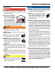
Safety Information Do not operate or service the equipment before reading the entire manual. Safety precautions should be followed at all times when operating this equipment. Failure to read and understand the safety messages and operating instructions could result in injury to yourself and others. Potential hazards associated with the operation of this equipment will be referenced with hazard symbols which may appear throughout this manual in conjunction with safety messages.
Safety Information general SaFetY CaUtion never operate this equipment without proper protective clothing, shatterproof glasses, respiratory protection, hearing protection, steel-toed boots and other protective devices required by the job or city and state regulations. never operate this equipment when not feeling well due to fatigue, illness or when under medication. never operate this equipment under the influence of drugs or alcohol.
Safety Information engine SaFetY Danger The engine fuel exhaust gases contain poisonous carbon monoxide. This gas is colorless and odorless, and can cause death if inhaled. The engine of this equipment requires an adequate free flow of cooling air. never operate this equipment in any enclosed or narrow area where free flow of the air is restricted. If the air flow is restricted it will cause injury to people and property and serious damage to the equipment or engine.
Safety Information FUel SaFetY Danger Do not start the engine near spilled fuel or combustible fluids. Diesel fuel is extremely flammable and its vapors can cause an explosion if ignited. Make sure the hitch and coupling of the towing vehicle are rated equal to, or greater than the trailer “gross vehicle weight rating.” alWaYS inspect the hitch and coupling for wear. never tow a trailer with defective hitches, couplings, chains, etc.
Safety Information eleCtriCal SaFetY Danger Do not touch output terminals during operation. Contact with output terminals during operation can cause electrocution, electrical shock or burn. The electrical voltage required to operate the generator can cause severe injury or even death through physical contact with live circuits. Turn generator and all circuit breakers oFF before performing maintenance on the generator or making contact with output terminals.
Safety Information BatterY SaFetY Danger Do not drop the battery. There is a possibility that the battery will explode. Do not expose the battery to open flames, sparks, cigarettes, etc. The battery contains combustible gases and liquids. If these gases and liquids come into contact with a flame or spark, an explosion could occur. Warning environmental SaFetY NOTICE Dispose of hazardous waste properly. Examples of potentially hazardous waste are used motor oil, fuel and fuel filters.
Specifications Model Type Table 1. Generator Specifications DCA300SSC/DCA300SSCU Revolving field, self ventilated, open protected type synchronous generator Star with Neutral 3 264 KW (330 kVA) 240 KW (300 kVA) Armature Connection Phase Standby Output Prime Output 3Ø Voltage (L-L/L-N) 208Y/120, 220Y/127, 240Y/139 Voltage Change-Over Bd. at 3Ø 240/139 3Ø Voltage (L-L/L-N) 416Y/240, 440Y/254, 480Y/277 Voltage Change-Over Bd. at 3Ø 480/277 1Ø Voltage (L-L/L-N) 240/120 Voltage Change-Over Bd.
Dimensions Figure 1. Dimensions Table 3. Dimensions Reference Letter Dimension in. (mm) Reference Letter Dimension in. (mm) A 39.76 in. (1,010 mm) F 43.90 in. (1,115 mm) B 43.90 in. (1,115 mm) G 149.61 in. (3,800 mm) C 23.03 in. (585 mm.) H 70.87 in. (1,800 mm) D 25.20 in. (640 mm) I 55.12 in. (1,400 mm) E 39.76 in. (1,010 mm) DCA300SSC / DCA300SSCU Gen. • operation and parts manual — rev.
Installation Figure 2. Typical Generator Grounding Application page 14 — DCA300SSC / DCA300SSCU Gen. • operation and parts manual — rev.
Installation Outdoor Installation Generator Grounding Install the generator in a area that is free of debris, bystanders, and overhead obstructions. Make sure the generator is on secure level ground so that it cannot slide or shift around. Also install the generator in a manner so that the exhaust will not be discharged in the direction of nearby homes. To guard against electrical shock and possible damage to the equipment, it is important to provide a good EARTH ground.
General Information Generator Open Delta Excitation System The MQ Power DCA300SSC and DCA300SSCU generators (Figure 3) are designed as a high quality portable (requires a trailer for transport) power source for telecom sites, lighting facilities, power tools, submersible pumps and other industrial and construction machinery. Each generator is equipped with the state of the art “OpenDelta” excitation system.
Major Components Table 4. Generator Major Components ITEM NO. DESCRIPTION 1 Muffler Assembly 2 Engine Assembly 3 Enclosure Assembly 4 Generator Assembly 5 Output Terminal Assembly 6 Battery Assembly 7 Fuel Tank Assembly 8 Generator Control Panel Assembly 9 Engine Operating Panel Assembly Figure 3. Major Components DCA300SSC / DCA300SSCU Gen. • operation and parts manual — rev.
Generator Control Panel Figure 4. Generator Control Panel The definitions below describe the controls and functions of the Generator Control Panel (Figure 4). 1. Pilot Lamp — Indicates the system is running. 2. Panel Light — Normally used in dark areas or at night time. When activated, panel lights will illuminate. When the generator is not in use be sure to turn the panel light switch to the OFF position. 3. AC Voltmeter — Indicates the output voltage present at the U,V, and W Output Terminal Lugs. 4.
Generator Control Panel MPEC Control Switch — This switch controls the running of the unit. If this switch is set to the OFF/RESET position, the unit will not run. When this switch is set to the manual position, the generator will start immediately. If the generator is to be connected to a building’s AC power source via a transfer switch (isolation), place the switch in the auto position.
ENGINE OPERATING PANEL 1 2 3 4 5 6 WATER TEMP. OIL PRESS. AIR FILTER COOLANT LEVEL 7 9 8 FUEL LEVEL ON OFF Figure 5. Engine Operating Panel The definitions below describe the controls and functions of the Engine Operating Panel (Figure 5). 1. Tachometer — Indicates engine speed in RPM’s for 60 Hz operation. This meter should indicate 1800 RPM’s when the rated load is applied. In addition a built in hour meter will record the number of operational hours that the generator has been in use. 2.
Notes DCA300SSC / DCA300SSCU Gen. • operation and parts manual — rev.
OUTPUT TERMINAL PANEL FAMILIARIZATION Output Terminal Panel Output Terminal Familiarization The Output Terminal Panel (Figure 6) shown below is located on the right-hand side (left from control panel) of the generator. Lift up on the cover to gain access to receptacles and terminal lugs.
OUTPUT TERMINAL PANEL FAMILIARIZATION 120 VAC GFCI Receptacles There are two 120 VAC, 20 amp GFCI (Duplex Nema 5-20R) receptacles provided on the output terminal panel. These receptacles can be accessed in any voltage change-over board configuration. Each receptacle is protected by a 20 amp circuit breaker. These breakers are located directly above the GFCI receptacles. Remember the load output (current) of both GFCI receptacles is dependent on the load requirements of the U, V, and W output terminal lugs.
OUTPUT TERMINAL PANEL FAMILIARIZATION Connecting Loads Over Current Relay Loads can be connected to the generator by the Output Terminal Lugs or the convenience receptacles (Figure 10). Make sure to read the operation manual before attempting to connect a load to the generator. An over current relay (Figure 11) is connected to the main circuit breaker. In the event of an overload, both the circuit breaker and the over current relay may trip.
Load Application Single Phase Load Three Phase Load Always be sure to check the nameplate on the generator and equipment to insure the wattage, amperage, frequency, and voltage requirements are satisfactorily supplied by the generator for operating the equipment. When calculating the power requirements for 3-phase power use the following equation: Generally, the wattage listed on the nameplate of the equipment is its rated output.
GENERATOR OUTPUTS Generator Output Voltages Maximum Amps A wide range of voltages are available to supply voltage for many different applications. Voltages are selected by applying jumpers (6) to the voltage change-over board (Figure 12). To obtain some of the voltages as listed in Table 7 (see below) will require a fine adjustment using the voltage regulator (VR) control knob located on the control panel. Table 8 shows the maximum amps the generator can provide. DO NOT exceed the maximum amps as listed.
GENERATOR OUTPUTS/gauge reading how to Read the ac ammeter and ac voltage gauges The AC ammeter and AC voltmeter gauges are controlled by the AC ammeter and AC voltmeter change-over switches. Both of these switches are located on the control panel and DO NOT effect the generator output. They are provided to help observe how much power is being supplied, produced at the UVWO terminals lugs.
OUTPUT TERMINAL PANEL CONNECTIONS UVWO Terminal Output Voltages Various output voltages can be obtained using the UVWO output terminal lugs. The voltages at the terminals are dependent on the placement of the jumpers plates (6) on the Voltage Change-Over Board and the adjustment of the Voltage Regulator Control Knob.
OUTPUT TERMINAL PANEL CONNECTIONS 3Ø-480V UVWO Terminal Output Voltages 1Ø-480V UVWO Terminal Output Voltages 1. Jumper the voltage change-over board for 480V operation as shown in Figure 23. This configuration uses 6 jumper plates in 3 different positions. Remember there are 2 jumper plates at every position. Every jumper plate must be used. 1. Make sure the voltage change-over board is jumpered for 480V operation as shown in Figure 23. Figure 23. Voltage Change-Over Board 480V Configuration 2.
inspection/SETUP Circuit Breakers To protect the generator from an overload, a 3-pole, 800 amp, main circuit breaker is provided to protect the U,V, and W Output Terminals from overload. In addition two single-pole, 20 amp GFCI circuit breakers are provided to protect the GFCI receptacles from overload. Three 50 amp load circuit breakers have also been provided to protect the auxiliary receptacles from overload. Make sure to switch ALL circuit breakers to the OFF position prior to starting the engine.
inspection/SETUP Refueling Procedure: WARNING 2. Open cabinet doors on the “right side” of the generator (from generator control panel position). Remove fuel cap and fill tank (Figure 30). Diesel fuel and its vapors are dangerous to your health and the surrounding environment. Avoid skin contact and/or inhaling fumes. 1. Level Tanks — Make sure fuel cells are level with the ground. Failure to do so will cause fuel to spill from the tank before reaching full capacity (Figure 29).
inspection/SETUP Coolant (Antifreeze/Summer Coolant/ Water) Cummins recommends antifreeze/summer coolant for use in their engines, which can be purchased in concentrate (and mixed with 50% demineralized water) or pre-diluted. See the Cummins Engine Owner’s Manual for further details. Cleaning the Radiator The engine may overheat if the radiator fins become overloaded with dust or debris. Periodically clean the radiator fins with compressed air.
inspection/SETUP Battery When connecting battery do the following: This unit is of negative ground DO NOT connect in reverse. Always maintain battery fluid level between the specified marks. Battery life will be shortened, if the fluid level are not properly maintained. Add only distilled water when replenishment is necessary. 1. NEVER connect the battery cables to the battery terminals when the MPEC Control Switch is in either the MANUAL position.
GENERATOR START-UP PROCEDURE (MANUAL) Before Starting Starting (Manual) CAUTION The engine’s exhaust contains harmful emissions. ALWAYS have adequate ventilation when operating. Direct exhaust away from nearby personnel. 1. Place the engine speed switch (Figure 37) in the LOW (down) position. Figure 37. Engine Speed Switch (Low) WARNING NEVER manually start the engine with the main, GFCI or auxiliary circuit breakers in the ON (closed) position. 2.
GENERATOR START-UP PROCEDURE (MANUAL) 6. The generator’s frequency meter (Figure 42) should be displaying the 60 cycle output frequency in HERTZ. 11. The coolant temperature gauge (Figure 47) will indicate the coolant temperature. Under normal operating conditions the coolant temperature should be between 167°~203°F (75°~95°C) (Green Zone). Figure 47. Coolant Temperature Gauge Figure 42. Frequency Meter 7. The generator’s AC-voltmeter (Figure 43) will display the generator’s output in VOLTS.
GENERATOR START-UP PROCEDURE (AUTO MODE) Starting (Auto Mode) DANGER Before connecting this generator to any building’s electrical system, a licensed electrician must install an isolation (transfer) switch. Serious damage to the building’s electrical system may occur without this transfer switch. CAUTION When connecting the generator to a isolation (transfer) switch, ALWAYS have power applied to the generator’s internal battery charger. This will ensure that the engine will not fail due to a dead battery.
GENERATOR SHUT-DOWN PROCEDURES WARNING NEVER stop the engine suddenly except in an emergency. Normal Shutdown Procedure Emergency Shutdown Procedure 1. To stop the engine in the event of an emergency, PUSH the emergency stop button (Figure 55) inward. This button is located on the engine operating panel, see Figure 5. To shutdown the generator, use the following procedure: 1. Place both the MAIN, GFCI and LOAD circuit breakers as shown in Figure 35 to the OFF position. 2.
Maintenance 10 Hrs DAILY X X X X X X Table 12.
Maintenance If the engine is operating in very dusty or dry grass conditions, a clogged air cleaner will result. This can lead to a loss of power, excessive carbon buildup in the combustion chamber and high fuel consumption. Change air cleaner more frequently if these conditions exists. Fuel Addition Add diesel fuel (the grade may vary according to season and locations). Removing Water from the Fuel Tank After prolonged use, water and other impurities accumulate in the bottom of the tank.
Maintenance To restart after running out of fuel, turn the switch to the “ON” position for 15-30 seconds. Try again, if needed. This unit is equipped with an automatic air bleeding system. Check Oil Level Check the crankcase oil level prior to each use, or when the fuel tank is filled. Insufficient oil may cause severe damage to the engine. Make sure the generator is level. The oil level must be between the two notches on the dipstick as shown in Figure 27.
Maintenance Jacket Water Heater and Internal Battery Charger 120 VAC Input Receptacles (OPTIONAL) This generator can be optionally equipped with two 120 VAC, 20 amp input receptacles located on the output terminal panel. The purpose of these receptacles is to provide power via commercial power to the jacket water heater and internal battery charger. If the generator will be used daily, the battery should normally not require charging.
Trailer Maintenance Trailer Maintenance This section is intended to provide the user with generic trailer service and maintenance information. The service and maintenance guidelines referenced in this section refer to a wide range of trailers. Remember periodic inspection of the trailer will ensure safe towing of the generator and will prevent personal injury and damage to the equipment. The definitions below describe some of the major components of a typical trailer that would be used with the generator.
Trailer Maintenance Brakes Hydraulic Surge Brakes Trailer brakes should be inspected the first 200 miles of operation. This will allow the brake shoes and drums to seat properly. After the first 200 mile interval, inspect the brakes every 3,000 miles. If driving over rough terrain, inspect the brakes more frequently. Figure 60 displays the major hydraulic surge brake components that will require inspection and maintenance.
Trailer Maintenance Tires/Wheels/Lug Nuts Suspension Tires and wheels are a very important and critical components of the trailer. When specifying or replacing the trailer wheels it is important the wheels, tires, and axle are properly matched. The leaf suspension springs and associated components (Figure 61) should be visually inspected every 6,000 miles for signs of excessive wear, elongation of bolt holes, and loosening of fasteners. Replace all damaged parts (suspension) immediately.
Trailer Maintenance Lug Nut Torque Requirements It is extremely important to apply and maintain proper wheel mounting torque on the trailer. Be sure to use only the fasteners matched to the cone angle of the wheel. Proper procedure for attachment of the wheels is as follows: 1. Start all wheel lug nuts by hand. 2. Torque all lug nuts in sequence (see Figure 62). DO NOT torque the wheel lug nuts all the way down. Tighten each lug nut in 3 separate passes as defined by Table 16. 3.
Trailer Wiring Diagram Figure 63. Trailer/Towing Vehicle Wiring Diagram page 46 — DCA300SSC / DCA300SSCU Gen. • operation and parts manual — rev.
Generator Wiring Diagram Figure 64. Generator Wiring Diagram DCA300SSC / DCA300SSCU Gen. • operation and parts manual — rev.
Engine Wiring Diagram Figure 65. Engine Wiring Diagram page 48 — DCA300SSC / DCA300SSCU Gen. • operation and parts manual — rev.
NOTES DCA300SSC / DCA300SSCU Gen. • operation and parts manual — rev.
Troubleshooting (Generator) Practically all breakdowns can be prevented by proper handling and maintenance inspections, but in the event of a breakdown, use Table 17 shown below for diagnosis of the Generator. If the problem cannot be remedied, consult our company’s business office or service plant. Symptom No Voltage Output Low Voltage Output High Voltage Output Circuit Breaker Tripped Table 17.
Troubleshooting (Engine Controller) Practically all breakdowns can be prevented by proper handling and maintenance inspections, but in the event of a breakdown, use Table 18 (Engine Controller Troubleshooting) as a basic guideline for troubleshooting the Microprocessor Engine Controller unit (MPEC). If the problem cannot be remedied, consult our company's business office or service plant. Table 18. Engine Controller Troubleshooting (MPEC) Symptom Possible Problem Solution Low oil level? Fill oil level.
Troubleshooting (Diagnostic lamp) The engine controller of this generator diagnoses problems that arise from the engine control system and the engine itself. Press the diagnostic button (Figure 66) on the diagnostic panel to determine if an engine malfunction has occurred. Figure 66. Diagnostic Panel Method of Operation 1. Normally, the diagnostic lamp will be dimly lit when the MPEC Control Switch is placed in the MANUAL position. 2.
notes DCA300SSC / DCA300SSCU Gen. • operation and parts manual — rev.
Explanation of Code in Remarks Column The following section explains the different symbols and remarks used in the Parts section of this manual. Use the help numbers found on the back page of the manual if there are any questions. NOTICE The contents and part numbers listed in the parts section are subject to change without notice. Multiquip does not guarantee the availability of the parts listed. Sample partS liSt no. 1 2% 2% 3 4 part no. part name QTY. remarKS 12345 BOLT .....................1 .....
Suggested Spare Parts dca300ssC/dca300ssCUWHISPERWATT GENERATOR with cummings qsl9-g3 DIESEL ENGINE 1 to 3 units Qty. P/N Description 1............0602015120...........HOSE, RADIATOR UPPER engine 1............0602015121...........HOSE, RADIATOR UPPER/lower 1............0602015122...........HOSE, RADIATOR LOWER 3............0602015244...........BELT, fan 1............4921744.................SENSOR, oil pressure 1............0602122272...........OIL PRESSURE UNIT 1............0602123267...........
GENERATOR ASSY. page 56 — DCA300SSC / DCA300SSCU Gen. • operation and parts manual — rev.
GENERATOR ASSY. NO. PART NO.
GENERATOR ASSY. (continued) page 58 — DCA300SSC / DCA300SSCU Gen. • operation and parts manual — rev.
GENERATOR ASSY. (continued) NO. 14 15 16 17 17A 18 19 20 20A 21 22 22A 22B 23 24 24A PART NO. C3154400003 0017106015 C3164600103 0010310030 0042510000 C2163700004 0070506208 0010312040 0042512000 C3132300014 0010106030 0041206000 0600815000 0605000012 0030020000 0040020000 PART NAME SUCTION COVER HEX HEAD BOLT COUPLING ADAPTER HEX HEAD BOLT WASHER, LOCK SPACER, BEARING BEARING, 6208ZZ HEX HEAD BOLT WASHER, LOCK COVER, FAN HEX HEAD BOLT WASHER, FLAT NUT RUBBER SUSPENSION HEX NUT WASHER, LOCK QTY.
control box ASSY. page 60 — DCA300SSC / DCA300SSCU Gen. • operation and parts manual — rev.
control box ASSY. NO. 1 2 3 4 4 4-1 5 6 7 8 9 10 11 12 13 14 15 16 17 18 19 20 21 22 23 23A 24 25 26 26A 26B 26C 27 28 28A 29 30 31 32 33 33A 33B 34 35 36 37 38 36 PART NO.
CONTROL BOX ASSY. (continued) page 62 — DCA300SSC / DCA300SSCU Gen. • operation and parts manual — rev.
CONTROL BOX ASSY. (continued) NO. 37 38 38A 39 40 41 42 43 44 45 46 47 48 49 50 51 52 53 54 55 55A 56 57 58 59 60 61 61A 62 63 63A 63B 63C 64 65 66 67 68 69 70 71 72 73 74 PART NO.
engine AND Radiator ASSY. page 64 — DCA300SSC / DCA300SSCU Gen. • operation and parts manual — rev.
engine AND Radiator ASSY. NO. 1 1A 1-1 1-1A 1-2 1-3 1-4 1-5 1-6 1-7 2 3 3A 3B 3C 3C 4 5 5A 6 7 8 9 10 11 11 12 13 14 15 16 17 18 19 20 21 22 23 24 25 26 27 28 29 30 31 32 PART NO.
engine and radiator ASSY. (continued) page 66 — DCA300SSC / DCA300SSCU Gen. • operation and parts manual — rev.
engine and radiator ASSY. (continued) NO. 33 34 35 36 37 38 39 39 40 41 42 43 44 45 46 47 48 49 50 51 52 52 53 53 54 55 56 57 58 59 60 60 61 61 62 63 64 65 66 67 68 69 69A 70 PART NO.
ENGINE operating panel ASSY. page 68 — DCA300SSC / DCA300SSCU Gen. • operation and parts manual — rev.
ENGINE operating panel ASSY. NO. 1 1 2 2 3 4 5 5A 5B 5C 6 7 8 9 10 11 12 13 14 14A 15 16 16 17 17A 17B 17C PART NO. C2351101903 M5351100003 0017106020 0017106016 0207006000 0602101000 0021008080 0030004000 0040008000 0041608000 0601830710 0601831557 0602120095 0602122093 0601842450 0602123092 0602121081 0602125091 0602103090 0601810244 M5483000003 0017110030 0016910030 0017110030 0030010000 0040010000 0041610000 PART NAME QTY. REMARKS OPERATING PANEL.............................................1..........
output terminal ASSY. page 70 — DCA300SSC / DCA300SSCU Gen. • operation and parts manual — rev.
output terminal ASSY. NO. 1 1 2 2 3 3 4 5 6 7 7 8 8A 8B 9 10 11 11 11-1 12 13 14 15 15 15A 16 16 17 17 18 19 19 20 21 21A 22 22 23 24 25 25 26 27 27 28 28 PART NO.
output terminal ASSY. page 72 — DCA300SSC / DCA300SSCU Gen. • operation and parts manual — rev.
output terminal ASSY. NO. 29 29 30 30 31 31 32 32 33 33 34 34 35 35 36 36 37 PART NO. 0017108020 0016908020 C2237102403 M5236100104 0019210030 014210040 0845054204 M9116000004 0805015604 M9310200004 C2237101504 M4236100604 C2237500104 M4236400304 0017106020 0016906016 7538070 PART NAME QTY. REMARKS HEX HEAD BOLT.........................................7.................DCA300SSC HEX HEAD BOLT.........................................7.................DCA300SSCU COVER, OUTPUT TERMINAL.....................1.
battery ASSY. (DCA300ssc) page 74 — DCA300SSC / DCA300SSCU Gen. • operation and parts manual — rev.
battery ASSY. (DCA300ssc) NO. 1 2 3 4 5 6 7 8 9 10 11 12 13 14 15 16 17 18 19 20 PART NO.
battery ASSY. (DCA300sscu) page 76 — DCA300SSC / DCA300SSCU Gen. • operation and parts manual — rev.
battery ASSY. (DCA300sscu) NO. 1 2 3 4 5 6 7 8 9 10 11 12 13 PART NO. 0602220196 M9310500404 M9104000004 0602220921 M5346900404 M5347900104 M4346400314 M5346900504 M5346200104 0017116030 0040516000 0017112025 0040512000 PART NAME BATTERY BATTERY SHEET BATTERY BAND BATTERY BOLT SET BATTERY CABLE BATTERY CABLE BATTERY CABLE BATTERY CABLE EARTH CABLE HEX HEAD BOLT TOOTHED WASHER HEX HEAD BOLT TOOTHED WASHER QTY. 2 2 1 2 1 1 1 1 2 1 1 1 1 REMARKS DCA300SSC / DCA300SSCU Gen.
muffler ASSY. page 78 — DCA300SSC / DCA300SSCU Gen. • operation and parts manual — rev.
muffler ASSY. NO. 1 1 2 3 4 5 5 6 6A 6B 6C 7 7 8 PART NO. C2331100002 M5330100102 0019210025 M5333000003 0602325066 C1334200304 M4333200004 0010312055 0030312000 0042512000 0041612000 C2331300004 M5331300004 0017108020 PART NAME QTY. REMARKS MUFFLER....................................................1.................DCA300SSC MUFFLER....................................................1.................DCA300SSCU HEX HEAD BOLT 4 EXHAUST PIPE 1 BEND BOLT CLAMP 1 GASKET......................................
fuel tank Assy. (DCA300ssc) page 80 — DCA300SSC / DCA300SSCU Gen. • operation and parts manual — rev.
fuel tank Assy. (DCA300ssc) NO. 1 1-1 1-2 1-3 1-4 2 3 4 5 6 7 8 9 10 11 12 13 14 15 16 17 18 19 20 21 PART NO.
fuel tank Assy. (DCA300sscU) page 82 — DCA300SSC / DCA300SSCU Gen. • operation and parts manual — rev.
fuel tank Assy. (DCA300sscU) NO. 1 1-1 2 3 4 5 6 7 8 9 10 11 12 13 14 15 16 17 18 19 20 PART NO.
enclosure ASSY. page 84 — DCA300SSC / DCA300SSCU Gen. • operation and parts manual — rev.
enclosure ASSY. NO. 1 1 2 2A 3 3 4 4A 5 5 5A 5A 6 6 7 7A 8 8A 9 10 11 11A 12 12 12A 12A 13 14 15 16 PART NO. C2413003202 M5413000004 C3414100104 M1413400004 C2414100004 M5413100204 0019208020 0019208020 C2414600304 M5413600104 C2494000304 M5493000004 0017108020 0016908020 M5423000002 M5493100003 M5423000102 M5493100003 0017108020 0019210025 C2424200003 M5424200203 C2424201504 M5424200103 C2494101104 M5494101604 0019208020 0845042703 0019208020 M5433000002 PART NAME QTY. REMARKS BASE.......................
enclosure ASSY. (continued) page 86 — DCA300SSC / DCA300SSCU Gen. • operation and parts manual — rev.
enclosure ASSY. (continued) NO. 17 17A 17B 17C 18 18A 18B 18C 19 19 20 21 21A 21A 22 23 23A 24 24A 25 26 27 28 29 29 30 30A 31 31 32 32A PART NO.
enclosure ASSY. (continued) page 88 — DCA300SSC / DCA300SSCU Gen. • operation and parts manual — rev.
enclosure ASSY. (continued) NO. 33 33 34 34 35 35 36 37 37 38 38 39 40 40A 40A 41 41A 41A 42 43 44 45 45 46 47 48 48A 49 50 51 51 51A 51A 52 53 54 55 PART NO.
enclosure ASSY. (continued) page 90 — DCA300SSC / DCA300SSCU Gen. • operation and parts manual — rev.
enclosure ASSY. (continued) NO. 56 56A 57 57A 58 58A 59 59A 60 60A 61 61A 62 62A 63 63A 64 65 65 66 66 67 67A 68 68 68A 68A 69 69 69A 69A 70 71 72 73 73 74 75 75 76 77 78 PART NO.
RUBBER SEALS ASSY. page 92 — DCA300SSC / DCA300SSCU Gen. • operation and parts manual — rev.
RUBBER SEALS ASSY. NO. 1 2 3 4 5 5 6 7 8 9 10 11 12 13 14 PART NO. 0229201400 0228901015 0228901250 0228901310 0228900650 0228900650 0228900650 0228900710 0229201300 0221200705 0228801210 0228100510 0228100120 0229200470 0229201130 PART NAME QTY. REMARKS SEAL RUBBER 4 SEAL RUBBER 4 SEAL RUBBER 3 SEAL RUBBER 3 SEAL RUBBER...............................................4.................. DCA300SSC SEAL RUBBER...............................................4..................
NAMEPLATE AND DECALS ASSY. (DCA300ssc) page 94 — DCA300SSC / DCA300SSCU Gen. • operation and parts manual — rev.
NAMEPLATE AND DECALS ASSY. (DCA300ssc) NO. 1-1 1-2 PART NO. C3550000703 C9522100003 PART NAME QTY. REMARKS DECAL : HANDLING PROCEDURES..........................1.................. C35000070 DECAL : CAUTION.......................................................2..................
NAMEPLATE AND DECALS ASSY. (Continued DCA300ssc) page 96 — DCA300SSC / DCA300SSCU Gen. • operation and parts manual — rev.
NAMEPLATE AND DECALS ASSY. (Continued DCA300ssc) NO. PART NO. 6-1 0800689404 6-2 0800689504 6-3 C9505300004 PART NAME QTY. REMARKS BATTERY GROUP DECAL : +................................................................ 1....................... S-2090 DECAL : -................................................................. 1....................... S-2091 DECAL : CAUTION.................................................. 1.......................
NAMEPLATE AND DECALS ASSY. (DCA300sscu) page 98 — DCA300SSC / DCA300SSCU Gen. • operation and parts manual — rev.
NAMEPLATE AND DECALS ASSY. (DCA300sscu) NO. 1-1 1-2 PART NO. M5550000303 M9520100603 PART NAME QTY. REMARKS DECAL : HANDLING PROCEDURES..........................1.................. M55000030 DECAL : CAUTION.......................................................2..................
NAMEPLATE AND DECALS ASSY. (Continued DCA300sscU) page 100 — DCA300SSC / DCA300SSCU Gen. • operation and parts manual — rev.
NAMEPLATE AND DECALS ASSY. (Continued DCA300sscU) NO. PART NO. 6-1 M9500300004 6-2 M9500300104 6-3 M9510100403 PART NAME QTY. REMARKS BATTERY GROUP DECAL : -................................................................. 1....................... M90030000 DECAL : +................................................................ 1....................... M90030010 DECAL : WARNING BATTERY CONNECT............. 1.......................
Terms and Conditions of Sale — Parts PAYMENT TERMS 5. Parts must be in new and resalable condition, in the original Multiquip package (if any), and with Multiquip part numbers clearly marked. 6. The following items are not returnable: Multiquip reserves the right to quote and sell direct to Government agencies, and to Original Equipment Manufacturer accounts who use our products as integral parts of their own products. a. SPECIAL EXPEDITING SERVICE Terms of payment for parts are net 30 days.
notes DCA300SSC / DCA300SSCU Gen. • operation and parts manual — rev.
Operation and Parts Manual HERE’S HOW TO GET HELP PLEASE HAVE THE MODEL AND SERIAL NUMBER ON-HAND WHEN CALLING United StateS Multiquip Corporate Office 18910 Wilmington Ave. Carson, CA 90746 Contact: mq@multiquip.com MQ Parts Department Tel.