PARTS AND OPERATION MANUAL OPERATION AND PARTS MANUAL DCA-45USI ULTRA-SILENTTM SERIES GENERATOR PARTS LIST NO. M1871400004B Revision #2 (04/22/05) THIS MANUAL MUST ACCOMPANY THE EQUIPMENT AT ALL TIMES.
PAGE 2 — DCA-45USI — OPERATION AND PARTS MANUAL (STD) — REV.
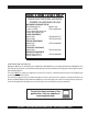
HERE'S HOW TO GET HELP PLEASE HAVE THE MODEL AND SERIAL NUMBER ON-HAND WHEN CALLING MQ POWER CORPORATE OFFICE 18910 Wilmington Ave. 800-421-1244 Carson, CA 90746 FAX: 310-632-2656 Email: mqpower@multiquip.com Internet: www.mqpower.com PARTS DEPARTMENT 800-427-1244 FAX: 800-672-7877 310-537-3700 FAX: 310-637-3284 SERVICE DEPARTMENT 800-835-2551 FAX: 310-638-8046 310-537-3700 TECHNICAL ASSISTANCE 800-478-1244 FAX: 310-631-5032 WARRANTY DEPARTMENT 800-835-2551, EXT. 279 FAX: 310-638-8046 310-537-3700, EXT.
TABLE OF CONTENTS MQ POWER DCA-45USI AC GENERA TOR GENERATOR Here's How To Get Help ............................................. 3 Table Of Contents ....................................................... 4 Parts Ordering Procedures ........................................ 5 DCA-45USI Specifications .......................................... 6 Dimensions .................................................................. 7 Safety Message Alert Symbols ...............................
PARTS ORDERING PROCEDURES When ordering parts, please supply the following information: ❒ ❒ ❒ ❒ ❒ ❒ ❒ Dealer account number Dealer name and address Shipping address (if different than billing address) Return fax number Applicable model number Quantity, part number and description of each part Specify preferred method of shipment: ✓ FedEx or UPS Ground Note: Unless otherwise indicated by customer, all ✓ FedEx or UPS Second Day or Third Day orders are treated as “Standard Orders”, and will ✓ FedEx or UPS Nex
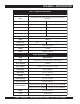
DCA-45USI — SPECIFICATIONS Table 1. Generator Specifications Model DCA-45USI Type Revolving field, self ventilated, open protected type synchronous generator Armature Connection Star with Neutral Zig Zag Phase 3 S in g le Standby Output 47.3 KVA (37.8 KW) 27.3 KW Prime Output 45 KVA (36 KW) 26 KW Voltage 240V or 480V 240/120V Frequency 60 Hz S pe e d 1,800 rpm Power Factor 0.8 1 Aux. AC Power Single Phase, 60 Hz Voltage 120 VAC Output 4.8 KW (2.
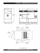
DCA-45USI — DIMENSIONS (SIDE AND FRONT) Figure 1. Dimensions DCA-45USI — OPERATION AND PARTS MANUAL (STD) — REV.
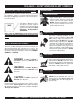
DCA-45USI — SAFETY MESSAGE ALERT SYMBOLS FOR YOUR SAFETY AND THE SAFETY OF OTHERS! Safety precautions should be followed at all times when operating this equipment. Failure to read and understand the Safety Messages and Operating Instructions could result in injury to yourself and others. NOTE This Owner's Manual has been developed to provide complete instructions for the safe and efficient operation of the MQ Power Model DCA45USI ULTRA-SILENT™ GENERATOR.
DCA-45USI — SAFETY MESSAGE ALERT SYMBOLS Accidental Starting ALWAYS place the engine ON/OFF switch in the OFF position, when the trowel is not in use. Over Speed Conditions NEVER tamper with the factory settings of the engine governor or settings. Personal injury and damage to the engine or equipment can result if operating in speed ranges above maximum allowable. Respiratory Hazard ALWAYS wear approved respiratory protection. Sight and Hearing hazard ALWAYS wear approved eye and hearing protection.
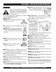
DCA-45USI — RULES FOR SAFE OPERATION ■ NEVER touch the hot exhaust manifold, muffler or cylinder. Allow these parts to Failure to follow instructions in this manual may cool before servicing engine or generator. lead to serious injury or even death! This equipment is to be operated by trained and qualified personnel only! This equipment is for industrial use only.
DCA-45USI — RULES FOR SAFE OPERATION ■ ALWAYS make sure that electrical circuits are properly grounded per the National Electrical Code (NEC) and local codes before operating generator. Severe injury or death! by electrocution can result from operating an ungrounded generator. ■ ALWAYS be sure the operator is familiar with proper safety precautions and operations techniques before using generator. ■ ALWAYS store equipment properly when it is not being used.
DCA-45USI — RULES FOR SAFE OPERATION ■ NEVER run engine without air filter. Severe engine damage Battery may occur. The battery contains acids that can cause injury to the eyes ■ ALWAYS service air cleaner frequently to prevent engine and skin. To avoid eye irritation, always wear safety glasses. Use well insulated gloves when picking up the battery. Use malfunction.
DCA-45USI — RULES FOR SAFE OPERATION Towing Safety Precautions ■ Avoid sharp turns. CAUTION: ■ Trailer should be adjusted to a level position at all times when towing. Conform to Department of Transportation ■ Raise and lock trailer wheel stand in up position when transporting. (DOT) Safety Towing Regulations before towing generator. ■ DOT Requirements include the following: z Connect and test electric brake operation.
DCA-45USI — INSTALLATION Figure 2. Typical Generator Grounding Application PAGE 14 — DCA-45USI — OPERATION AND PARTS MANUAL (STD) — REV.
DCA-45USI — INSTALLATION Outdoor Installation Generator Grounding Install the generator in a clear area. Make sure the generator is on secure level ground so that it cannot slide or shift around. Also install the generator in a manner so that the exhaust will not be discharged in the direction of nearby homes. To guard against electrical shock and possible damage to the equipment, it is important to provide a good EARTH ground. The installation site must be relatively free from moisture and dust.
DCA-45USI — TOWING SAFETY PRECAUTIONS ■ ALWAYS attach trailer’s safety chain to bumper of towing vehicle. Towing Safety Precautions CAUTION CAUTION: Check with your local county or state safety towing regulations before towing your generator. To reduce the possibility of an accident while transporting the generator on public roads, always make sure the trailer (Figure 3) that supports the generator and the towing vehicle are in good operating condition and both units are mechanically sound.
DCA-45USI — TRAILER SPECIFICATIONS 5. Frame Width - Measurement is from fender to fender ALWAYS make sure the trailer is in good 6. Jack Stand - Trailer support device with maximum pound requirement from the tongue of the trailer. operating condition. Check the tires for proper inflation and wear. Also check the 7. Coupler - Type of hitch used on the trailer for towing. wheel lug nuts for proper tightness. 8. Tire Size - Indicates the diameter of the tire in inches (10,12,14, etc.
DCA-45USI — GENERATOR DECALS The DCA-45USI generator is equipped with a number of safety decals. These decals are provided for operator safety and maintenance information. The illustration below and on the preceding page show the decals as they appear on the machine. Should any of these decals become unreadable, replacements can be obtained from your dealer. PAGE 18 — DCA-45USI — OPERATION AND PARTS MANUAL (STD) — REV.
DCA-45USI — GENERATOR DECALS DCA-45USI — OPERATION AND PARTS MANUAL (STD) — REV.
DCA-45USI — GENERAL INFORMATION DCA-45USI FAMILIARIZATION Generator The MQ Power Model DCA-45USI (Figure 4) is a 36 kW generator that is designed as a high quality portable (requires a trailer for transport) power source for telecom sites, lighting facilities, power tools, submersible pumps and other industrial and construction machinery.
DCA-45USI — MAJOR COMPONENTS Table 3. Generator Major Components ITEM NO. Figure 4. Major Components DESCRIPTION 1 Muffler Assembly 2 Engine Assembly 3 Air Cleaner Assembly 4 Generator Assembly 5 Output Terminal Assembly 6 Fuel Tank Assembly 7 Battery Assembly 8 Generator Control Panel Assembly 9 Engine Operating Panel Assembly DCA-45USI — OPERATION AND PARTS MANUAL (STD) — REV.
DCA-45USI — GENERATOR CONTROL PANEL Figure 5. Generator Control Panel The definitions below describe the controls and functions of Located behind the generator control panel is the Generator Control Box. This box contains some of the necessary the DCA-45USI "Generator Control Panel" (Figure 5). 1. Main Circuit Breaker – This three-pole, 110 amp main electronic components required to make the generator breaker is provided to protect the U,V, and W Output function. 2. 3. 4. 5. 6. 7.
DCA-45USI — ENGINE OPERATING PANEL The definitions below describe the controls and functions of the DCA-45USI "Engine Operating Panel" (Figure 6). 1. Panel Light - Normally used in dark places or at night. When activated, panel will luminate. When the generator is not in use, turn the panel light switch to the OFF position. 2. Panel Light Switch- When activated, will turn on control panel light. 3. Oil Pressure Lamp - Indicates that the oil pressure is too low and will shut down the engine. 4.
DCA-45USI — OUTPUT TERMINAL PANEL FAMILIARIZATION Output Terminal Panel The Output Terminal Panel (Figure 7) shown below is located on the right-hand side (left from control panel) of the generator. Lift up on the cover to gain access to receptacles and terminal lugs.
DCA-45USI — OUTPUT TERMINAL PANEL FAMILIARIZATION 120 VAC GFCI Receptacles There are two 120 VAC, 20 amp GFCI (Duplex Nema 5-20R) recepacles provided on the output terminal panel. These receptacles can be accessed in any voltage selector switch position. Each receptacle is protected by a 20 amp circuit breaker. These breakers are located directly above the GFCI receptacles. Remember the load output (current) of both GFCI receptacles is dependent on the load requirements of the UVWO terminals.
DCA-45USI — OUTPUT TERMINAL PANEL FAMILIARIZATION Connecting Loads Loads can be connected to the generator by using the Output Terminal Lugs or the convienience receptacles (See Figure 12). Make sure to read the operation manual before attempting to connect a load to the generator. Blower Fan This unit has an intake fan located at the rear of the machine to draw outside air into the cabinet to cool the engine. The fan has a 10 amp AC fuse located beneath the Voltage Selector Switch (Figure 14).
DCA-45USI — LOAD APPLICATION Single Phase Load Three Phase Load Always be sure to check the nameplate on the generator and equipment to insure the wattage, amperage, frequency, and voltage requirements are satisfactorily supplied by the generator for operating the equipment. Generally, the wattage listed on the nameplate of the equipment is its rated output.
DCA-45USI — GENERATOR OUTPUTS Voltage Selector Switch Generator Amperage The voltage selector switch (Figure 15) is located above Table 7 describes the generator’s current output capability the UVWO Hard Wire Hook-up Panel. It has been provided for both 1Ø-phase and 3Ø phase applications. for ease of voltage selection. Table 7. Generator Ampere Ratings DCA-45USJ kW kVA 120V 208V 240V Single Phase 26 N/A 108A x 2 N/A 108A 480V N/A Three Phase* 36 45 N/A 125A 108A 54A * Power Factor = 0.
DCA-45USI — GAUGE READING How to Read the Output Terminal Gauges. The gauges and selector switches on the control panel DO NOT effect the generator output. They are provided to help observe how much power is being supplied at the Output Terminal Lugs. Reading Amperage To determine the amperage at a terminal lug, set the AC Ammeter Change-Over Switch to the appropriate setting (Figure 19) to activate the AC Ammeter Gauge (Figure 20) and read the available amperage at the terminal lug.
DCA-45USI — OUTPUT TERMINAL PANEL CONNECTIONS 3Ø 208V/1Ø120V Output Terminal Lug Voltages UVWO Terminal Output Voltages Various output voltages can be obtained using the using the 1. Place the voltage selector switch in the 3Ø 240/139 position as shown in Figure 24. Output Terminal Lugs. The voltages at the terminals are dependent on the position of the Voltage Selector Switch Use this position for and the adjustment of the Voltage Regulator Control Knob. 3Ø-208 or 1Ø120V.
DCA-45USI — OUTPUT TERMINAL PANEL CONNECTIONS 3Ø 480/277 Output Terminal Lug Voltages 1Ø 240V/120V Output Terminal Lug Voltages 1. Place the voltage selector switch in the 3Ø 480/277 1. Place the voltage selector switch in the 1Ø 240/120 position as shown in Figure 26. position as shown in Figure 28. Figure 26. Voltage Selector Switch 480/277V Three-Phase Position Figure 28. Voltage Selector Switch 240/120V Single-Phase Position 2. Connect the load wires to the Output Terminal Lugs as 2.
DCA-45USI — PRE-SETUP Circuit Breakers Fuel Check To protect the generator from an overload, a 3-pole, 110 amp, main circuit breaker is provided to protect the UVW output terminals from overload. In addition two single-pole, 20 amp GFCI circuit breakers are provided to protect the GFCI receptacles from overload. Three 50 amp load circuit breakers have also been provided to protect the auxiliary receptacles from overload.
DCA-45USI — PRE-SETUP Refueling Procedure: 2. DANGER: Open cabinet doors on the generator. Locate and remove the fuel tank cap and fill tank (Figure 33). Diesel fuel and its vapors are dangerous to your health and the surrounding environment. Avoid skin contact and/or inhaling fumes. 1. Level Tanks – make sure fuel cells are level with the ground. Failure to do so will cause fuel to spill from the tank before reaching full capacity (Figure 32).
DCA-45USI — PRE-SETUP Coolant (Ethylane Glycol [Green] / Water — 50/50 mix) Use only drinkable tap water. If hard water or water with many impurities is used, the inside of the engine and radiator may become coated with deposits and cooling efficiency will be reduced. An anticorrosion additive added to the water will help prevent deposits and corrosion in the cooling system. See the engine manual for further details.
DCA-45USI — PRE-SETUP Battery When connecting battery do the following: This unit is of negative ground DO NOT connect in reverse. 1. NEVER connect the battery cables to the battery Always maintain battery fluid level between the specified terminals when the ignition switch is in the PRE-HEAT/ marks. Battery life will be shortened, if the fluid level are not RUN position. ALWAYS make sure that the ignition switch properly maintained.
DCA-45USI — GENERATOR START-UP PROCEDURE WARNING: 3. Close all engine enclosure doors (Figure 40). The engine's exhaust contains harmful emissions. ALWAYS have adequate ventilation when operating. Direct exhaust away from nearby personnel. Before Starting CAUTION: NEVER! manually start the engine with the main, GFCI or auxiliary circuit breakers in the ON (closed) position. Figure 40. Engine Enclosure Doors 4. Place the voltage selector switch in the desired voltage position (Figure 41). 1.
DCA-45USI — GENERATOR START-UP PROCEDURE 6. Turn the ignition key to the START position (Figure 44). 9. The generator's voltage meter (Figure 46) displays the Once the engine starts, release the ignition key and output voltage in VOLTS. allow it to return to the PRE-HEAT/RUN position (Figure 42). If the engine fails to start after 10 seconds, wait approximately 30 seconds and repeat steps 5-6. Figure 46. AC Voltmeter Figure 44. Ignition Switch (Start Position) 10.
DCA-45USI — GENERATOR START-UP PROCEDURE 12. The engine oil pressure gauge (Figure 49) will indicate the oil pressure of the engine. Under normal operating conditions the oil pressure is approximately 15. Turn the main, GFCI, and aux. circuit breakers to the ON position (Figure 52). Figure 49. Oil Pressure Gauge 13. The coolant temperature gauge (Figure 50) will indicate the coolant temperature. Under normal operating conditions the coolant temperature is between 165 and 203° degrees Fahrenheit.
DCA-45USI — GENERATOR SHUT-DOWN PROCEDURE Normal Shut-down Procedure To shutdown the generator, use the following procedure: 1. Switch the MAIN, AUX and GFCI circuit breakers (Figure 54) to the OFF position (no load). Emergency Shut-down Procedure 1. To shut-down the engine in the event of an emergency, switch the MAIN, GFCI and LOAD (Figure 54) circuit breakers to OFF position. 2. Turn the ignition switch key to the STOP position (Figure 55).
DCA-45USI — MAINTENANCE 10 Hrs DAILY TABLE 14.
DCA-45USI — MAINTENANCE Air Removal If air enters the fuel injection system of a diesel engine, starting becomes impossible. After running out of fuel, or after disassembling the fuel system, bleed the system according to the following procedure. CAUTION: Allow engine to cool when flushing out radiator. Flushing the radiator while hot could cause serious burns from water or steam. To restart after running out of fuel, turn the switch to the ON position for 15-30 seconds. Try again, if needed.
DCA-45USI — TRAILER BRAKES MAINTENANCE Brakes Trailer brakes should be inspected the first 200 miles of operation. This will allow the brake shoes and drums to seat properly. After the first 200 mile interval, inspect the brakes every 3,000 miles. If driving over rough terrain, inspect the brakes more frequently. Figure 74 displays the major hydraulic surge brake components that will require inspection and maintenance.
DCA-45USI — TRAILER MAINTENANCE Tires/Wheels/Lug Nuts Tires and wheels are a very important and critical components of the trailer. When specifying or replacing the trailer wheels it is important the wheels, tires, and axle are properly matched. CAUTION: Suspension The leaf suspension springs and associated components (Figure 57) should be visually inspected every 6,000 miles for signs of excessive wear, elongation of bolt holes, and loosening of fasteners.
DCA-45USI — TRAILER MAINTENANCE Lug Nut Torque Requirements It is extremely important to apply and maintain proper wheel mounting torque on the trailer. Be sure to use only the fasteners matched to the cone angle of the wheel. Proper procedure for attachment of the wheels is as follows: 1. Start all wheel lug nuts by hand. 2. Torque all lug nuts in sequence. See Figure 58. DO NOT torque the wheel lug nuts all the way down. Tighten each lug nut in 3 separate passes as defined by Table 18. 3.
DCA-45USI — TRAILER WIRING DIAGRAM Figure 59. Trailer/Towing Vehicle Wiring Diagram DCA-45USI — OPERATION AND PARTS MANUAL (STD) — REV.
DCA-45USI — ENGINE WIRING DIAGRAM Figure 60. Engine Wiring Diagram PAGE 46 — DCA-45USI — OPERATION AND PARTS MANUAL (STD) — REV.
DCA-45USI — ENGINE WIRING DIAGRAM Figure 60. Engine Wiring Diagram(Continued) DCA-45USI — OPERATION AND PARTS MANUAL (STD) — REV.
DCA-45USI — GENERATOR WIRING DIAGRAM Figure 61. Generator Wiring Diagram PAGE 48 — DCA-45USI — OPERATION AND PARTS MANUAL (STD) — REV.
DCA-45USI — TROUBLESHOOTING (GENERATOR) Practically all breakdowns can be prevented by proper handling and maintenance inspections, but in the event of a breakdown, use the table (Table 19) shown below for basic Generator Troubleshooting. If the problem cannot be remedied, consult our company's business office or service plant. TABLE 19.
EXPLANATION OF CODE IN REMARKS COLUMN How to read the marks and remarks used in this parts book. Items Found In the “Remarks” Column Serial Numbers-Where indicated, this indicates a serial number range (inclusive) where a particular part is used. Model Number-Where indicated, this shows that the corresponding part is utilized only with this specific model number or model number variant.
DCA-45USI — SUGGESTED SPARE PARTS DCA-45USI w/ ISUZU BB-4JG1T 1 TO 3 UNITS Qty. P/N Description 3 ......... 8970497081 .............. OIL FILTER 3 ......... 8943692993 .............. FUEL FILTER 3 ......... 0602046681 .............. AIR ELEMENT 1 ......... 0602122272 .............. UNIT, OIL PRESSURE 1 ......... 0602123260 .............. UNIT WATER TEMPERATURE 1 ......... 8972606490 .............. FAN BELT 3 ......... 8944024980 .............. KEY, STARTER SWITCH 1 ......... 0605505070 ..............
DCA-45USI — GENERATOR ASSY. GENERATOR ASSY. PAGE 52 — DCA-45USI — OPERATION AND PARTS MANUAL (STD) — REV.
DCA-45USI — GENERATOR ASSY. GENERATOR ASSY. NO. PART NO.
DCA-45USI — CONTROL BOX ASSY. CONTROL BOX ASSY. PAGE 54 — DCA-45USI — OPERATION AND PARTS MANUAL (STD) — REV.
DCA-45USI — CONTROL BOX ASSY. CONTROL BOX ASSY. NO. PART NO. 1 M1214000102 2 0601808825 3 0021005080 4 0601823863 5 0027104016 6 0601820671 7 0027105016 8 0601806116 9 0027106016 10 0601820845 11 0601820846 12 0027104016 12A 0207004000 13 M1213500303 14 0016906016 15 M1201000004 15A TBD 16 M1215601204 17 0027103010 18 0016906016 19 0330000530 20 M1215601104 21 0016906016 22 0016906016 22A 0040506000 23 M1224000003 24 0601807641 25 0601808986 26 0601801040 27 0601806859 28 0601801041 PART NAME QTY.
DCA-45USI — CONTROL BOX ASSY. CONTROL BOX ASSY. PAGE 56 — DCA-45USI — OPERATION AND PARTS MANUAL (STD) — REV.
DCA-45USI — CONTROL BOX ASSY. CONTROL BOX ASSY. NO. PART NO.
DCA-45USI — ENGINE AND RADIATOR ASSY. ENGINE AND RADIATOR ASSY. PAGE 58 — DCA-45USI — OPERATION AND PARTS MANUAL (STD) — REV.
DCA-45USI — ENGINE AND RADIATOR ASSY. ENGINE AND RADIATOR ASSY. NO. PART NO. PART NAME QTY. REMARKS 1 M1924200014 ENGINE ...............................................................1 ........ ISUZU BB-4JG1T 1-1 897049-7081 CARTRIDGE, OIL FILTER ...................................1 ........ REPLACES 0602041214 2 0605000048 RUBBER SUSPENSION 2 3 0030010000 HEX, NUT 2 4 0040010000 SPRING WASHER 2 5 0041210000 PLAIN WASHER 2 6 M1923200084 RADIATOR ...........................................................
DCA-45USI — ENGINE AND RADIATOR ASSY. ENGINE & RADIATOR ASSY. PAGE 60 — DCA-45USI — OPERATION AND PARTS MANUAL (STD) — REV.
DCA-45USI — ENGINE AND RADIATOR ASSY. ENGINE & RADIATOR ASSY. NO. PART NO.
DCA-45USI — OUTPUT TERMINAL ASSY. OUTPUT TERMINAL ASSY. PAGE 62 — DCA-45USI — OPERATION AND PARTS MANUAL (STD) — REV.
DCA-45USI — OUTPUT TERMINAL ASSY. OUTPUT TERMINAL ASSY. NO. PART NO.
DCA-45USI — BATTERY ASSY. BATTERY ASSY. PAGE 64 — DCA-45USI — OPERATION AND PARTS MANUAL (STD) — REV.
DCA-45USI — BATTERY ASSY. BATTERY ASSY. NO. PART NO. 1 0602220187 2 M9310500014 3 M9103000304 4 0602220920 5 0040006000 6 M1347200004 7 M1347200104 8 0016910020 9 0040510000 10 PART NAME QTY. REMARKS BATTERY 1 BATTERY SHEET 1 BATTERY BAND 1 BATTERY BOLT SET 2 SPRING WASHER 2 BATTERY CABLE 1 BATTERY CABLE 1 HEX, HEAD BOLT 2 TOOTHED WASHER 2 CABLE, GROUND ...............................................1 ..................... MAKE LOCALLY DCA-45USI — OPERATION AND PARTS MANUAL (STD) — REV.
DCA-45USI — MUFFLER ASSY. MUFFLER ASSY. PAGE 66 — DCA-45USI — OPERATION AND PARTS MANUAL (STD) — REV.
DCA-45USI — MUFFLER ASSY. MUFFLER ASSY. NO. PART NO. 1 M1331100102 2 0017112030 3 M1334000003 4 0602320101 5 0039308000 6 0602325088 PART NAME QTY. REMARKS MUFFLER 1 HEX, HEAD BOLT 4 EXHAUST PIPE 1 GASKET .............................................................1 ........ 894369-0210 HEX, NUT 6 SEAL CLAMP 1 DCA-45USI — OPERATION AND PARTS MANUAL (STD) — REV.
DCA-45USI — FUEL TANK ASSY. FUEL TANK ASSY. PAGE 68 — DCA-45USI — OPERATION AND PARTS MANUAL (STD) — REV.
DCA-45USI — FUEL TANK ASSY. FUEL TANK ASSY. NO. PART NO. 1 M1364000102 1A 0605505070 1B 0605501072 1C 0605516090 2 M1364200004 3 M9310500104 4 0016908020 5 0016908065 5A 0207008000 6 0191301300 7 0605515109 8 897211-2730 8A 897213-4720 9 M1367700004 10 0016908020 11 0191200550 12 0191201600 13 0605515108 14 0191300750 15 0605515109 15 0222100700 PART NAME QTY.
DCA-45USI — ENCLOSURE ASSY. ENCLOSURE ASSY. PAGE 70 — DCA-45USI — OPERATION AND PARTS MANUAL (STD) — REV.
DCA-45USI — ENCLOSURE ASSY. ENCLOSURE ASSY. NO. PART NO.
DCA-45USI — ENCLOSURE ASSY. ENCLOSURE ASSY. PAGE 72 — DCA-45USI — OPERATION AND PARTS MANUAL (STD) — REV.
DCA-45USI — ENCLOSURE ASSY. ENCLOSURE ASSY. NO. PART NO.
DCA-45USI — ENCLOSURE ASSY. ENCLOSURE ASSY. PAGE 74 — DCA-45USI — OPERATION AND PARTS MANUAL (STD) — REV.
DCA-45USI — ENCLOSURE ASSY. ENCLOSURE ASSY. NO. PART NO. 49A M1494400404 50 M1454000103 50A M1494400104 51 M1454000503 51A M1494400504 52 M1454000303 52A M1494400304 53 M9113000002 53A C9312500004 54 0021806016 54A 0030006000 55 M9112100404 56 M9112100504 57 M9112100604 58 0016908020 59 0016908020 60 0601850097 61 0027208025 62 0605503062 63 M1414800104 64 0017108020 PART NAME QTY.
DCA-45USI — RUBBER SEALS ASSY. RUBBER SEALS ASSY. PAGE 76 — DCA-45USI — OPERATION AND PARTS MANUAL (STD) — REV.
DCA-45USI — RUBBER SEALS ASSY. RUBBER SEALS ASSY. NO. PART NO.
DCA-45USI — NAMEPLATE AND DECALS ASSY. NAME PLATE ASSY. PAGE 78 — DCA-45USI — OPERATION AND PARTS MANUAL (STD) — REV.
DCA-45USI — NAMEPLATE AND DECALS ASSY. NAME PLATE ASSY. NO. PART NO.
Effective: October 1, 2002 PAYMENT TERMS TERMS AND CONDITIONS OF SALE — PARTS 5. Parts must be in new and resalable condition, in the original Multiquip package (if any), and with Multiquip part numbers clearly marked. 6. The following items are not returnable: Terms of payment for parts are net 10 days. FREIGHT POLICY All parts orders will be shipped collect or prepaid with the charges added to the invoice. All shipments are F.O.B. point of origin.
NOTE PAGE DCA-45USI — OPERATION AND PARTS MANUAL (STD) — REV.
PARTS AND OPERATION MANUAL OPERATION AND PARTS MANUAL HERE'S HOW TO GET HELP PLEASE HAVE THE MODEL AND SERIAL NUMBER ON-HAND WHEN CALLING MQ POWER CORPORATE OFFICE 18910 Wilmington Ave. 800-421-1244 FAX: 310-632-2656 Carson, CA 90746 Email: mqpower@multiquip.com Internet: www.mqpower.