OPERATION AND PARTS MANUAL © COPYRIGHT 2002, MULTIQUIP INC. Multiquip Submersible Pump Model ST-3050D Revision #1 (11/18/02) MULTIQUIP INC.
HERE'S HOW TO GET HELP PLEASE HAVE THE MODEL AND SERIAL NUMBER ON-HAND WHEN CALLING PARTS DEPARTMENT 800/427-1244 or 310/537-3700 FAX: 800/672-7877 or 310/637-3284 SERVICE DEPARTMENT 800/478-1244 or 310/537-3700 FAX: 310 - 537-4259 WARRANTY DEPARTMENT 800/421-1244, EXT. 279 or 310/537-3700 FAX: 310 - 537-1173 MAIN 800/421-1244 or 310/537-3700 FAX: 310 - 537-3927 PAGE 2 — ST-3050D — PARTS & OPERATION MANUAL — REV.
ST-3050D SUBMERSIBLE PUMP — TABLE OF CONTENTS Here's How To Get Help ............................................2 Table Of Contents .....................................................3 Parts Ordering Procedures .......................................4 Safety Message Alert Symbols .................................5 Rules For safe Operation ..................................... 6-7 Specifications (Pump) ...............................................7 General Information ...................................
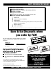
PARTS ORDERING PROCEDURES ■ ■ ■ ■ ■ ■ ■ Dealer account number Dealer name and address Shipping address (if different than billing address) Return fax number Applicable model number Quantity, part number and description of each part Specify preferred method of shipment: • • • • UPS Ground UPS Second Day or Third Day* UPS Next Day* Federal Express Priority One (please provide us with your Federal Express account number)* • • Airborne Express* Truck or parcel post *Normally shipped the same day the order
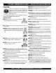
ST-3050D SUBMERSIBLE PUMP— SAFETY MESSAGE ALERT SYMBOLS FOR YOUR SAFETY AND THE SAFETY OF OTHERS! Safety precautions should be followed at all times when operating this equipment. Failure to read and understand the Safety Messages and Operating Instructions could result in injury to yourself and others. NOTE This Owner's Manual has been developed to provide complete instructions for the safe and efficient operation of the Multiquip Model ST-3050D Submersible Pump.
ST-3050D SUBMERSIBLE PUMP — RULES FOR SAFE OPERATION ■ ALWAYS make sure submersible pump is grounded. CAUTION: Failure to follow instructions in this manual may lead to serious injury or even death! This equipment is to be operated by trained and qualified personnel only! This equipment is for industrial use only. The following safety guidelines should always be used when operating the ST-3050D Submersible Pump: GENERAL SAFETY ■ DO NOT operate or service this equipment before reading this entire manual.
ST-3050D SUBMERSIBLE PUMP — RULES FOR SAFE OPERATION ■ ALWAYS make sure that electrical circuits are properly grounded per the National Electrical Code (NEC) and local codes before operating pump. Severe injury or death by electrocution can result from operating an ungrounded pump. . Emergencies ■ ALWAYS know the location of the nearest fire extinguisher. ■ NEVER use this pump to remove water from a swimming pool when people are in the water.
ST-3050D SUBMERSIBLE PUMP — SPECIFICATIONS Table 1. Specifications (Pump) Model ST-3050D Type Submersible Trash Pump Suction & Discharge Size Maximum Pumping Capacity Max. Solids Diameter Max. Head 86 ft. (26.00 meters) 5 HP (3.75 Kw) Voltage Phase 230/460 3ø Star ting Amps 77 @ 230 VAC 39 @ 460 VAC Running Amps 14.2 @ 230 VAC 7.1 @ 460 VAC Control Box Required Yes Thermal Overload Protection Yes 1 Rotation Counter-Clockwise Mechanical Oil Seal Capacity 180 cc. (.
ST-3050D SUBMERSIBLE PUMP — GENERAL INFORMATION Introduction The Multiquip Model ST-3050D submersible pump is designed to pump water and is used for the draining (de-watering) of swimming pools, well casings construction sites, cofferdams, manholes, transformer vaults and excavations. A vortex type impeller is attached to the output shaft of a 5.0 HP electric motor which provides adequate power for general purpose pumping.
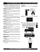
ST-3050D SUBMERSIBLE PUMP — COMPONENTS Figure 1. Submersible Pump Components Figures 1 shows the location of the basic components, for the ST-3050D Submersible Pump. Listed below is a brief explanation of each component. 1. Strainer Base – This strainer base is made of stainless steel which is resistant to hardware corrosion. DO NOT pump large objects or debris with this pump. This pump is for pumping water only. For de-watering purposes, always place the strainer base on a platform. 2.
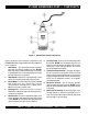
ST-3050D SUBMERSIBLE PUMP — APPLICATION (FLOAT SWITCHES) Float Switch Theory Float Switch (Dual) There is a tilt-sensitive mercury switch hermetically sealed within each float. As the liquid level (water) rises or falls, the float changes its angle until the mercury switch makes (close) or breaks (open) the circuit. Float switches (Figure 2) are used for the unattended operation of the submersible pump. The ST-3050D pump requires the use of a control box to perform this function.
ST-3050D SUBMERSIBLE PUMP — CONTROL BOXES Control Boxes CONTROL BOX Control boxes (Figure 3) are available for remote control and thermal shut-down capability for the submersible pump. These water resistant control boxes provide electronic overload protection, watertight housing and glands to prevent water from leaking into the box, and a float switch interface.
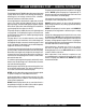
ST-3050D SUBMERSIBLE PUMP/CTRL. BOX — INSTALLATION (CB200) DANGER: POWER CORD REQUIREMENTS When routing the three phase power via a power cord to the control box, ALWAYS use the correct wire size. Please reference Table 3 below (Cord Length/Wire Size) to determine the correct wire size. Incorrect wire size can adversely affect the performance of the pump. To place the ST-3050D submersible pump into operation requires the use of a control box.
ST-3050D SUBMERSIBLE PUMP — 230/460 VAC VOLTAGE SELECTION 230/460 VAC Voltage Selection The ST-3050D submersible pump is factory set at 230 VAC. To change the voltage from 230 VAC to 460 VAC, perform the following: 1. Remove the four retaining screws that secure the power cord gland assembly to the pump casing, and pull the 230 VAC female plug (Figure 4) from the pump's cavity. 2. 3. Re-install the power cord gland assembly back into the pump's cavity. Make sure that the gland is seated correctly.
ST-3050D SUBMERSIBLE PUMP — PUMP WIRING DIAGRAM Figure 5. Pump Wiring Diagram ST-3050D — PARTS & OPERATION MANUAL — REV.
ST-3050D SUB. PUMP/CTRL. BOX — TRANSFORMER WIRING (CB200) TRANSFORMER 230/460 VOLTAGE SETTINGS WARNING: ALWAYS make sure that the transformer is set CAUTION: to the correct output voltage. Incorrect transformer Transformer 230/460 Voltage Settings: Pump motors are factory set at 230 VAC. The transformer (Figure 6) of this control box must be set to the voltage requirements of the pump in use. Refer to the attached wiring diagram located inside the "Control Box" or reference Figures 7 & 8.
ST-3050D SUB. PUMP/CONTRL. BOX — WIRING DIAGRAM (CB200) THREE PHASE WIRING CONNECTIONS EXTERNAL 3-PHASE (230 OR 460 VOLT) POWER SOURCE M CIRCUIT BREAKER RED WHITE BLACK L1 L1 L2 L3 GREEN L2 L3 ELECTRONIC OVERLOAD UNIT TERMINALS H1 GROUND H3 H2 O/L 1 2 3 4 5 6 CONTROL TRANSFORMER 50VA CPT SEE FIGURE 1 FOR JUMPER SELECTION 230 0R 460 VAC SELECTION.
ST-3050D SUB. PUMP/CTRL. BOX — 3Ø PWR. INSTALLATION (CB200) 3-PHASE POWER CORD (INPUT TO BOX) INSTALLATION 3-PHASE POWER INSTALLATION (OUTPUT TO PUMP) 1. The three phase input power cord should have four wires. Each wire is color coded. The colors are RED, WHITE, BLACK and GREEN. 1. The three phase output power cord should have four wires. Each wire is color coded. The colors are RED, WHITE, BLACK and GREEN. 2.
ST-3050D SUB. PUMP/CTRL BOX — 3Ø PWR. INSTALLATION (CB200) Figure 8. Three Phase Control Box/Pump System Diagram ST-3050D — PARTS & OPERATION MANUAL — REV.
ST-3050D SUBMERSIBLE PUMP/CTRL. BOX — PRE SETUP (CB200) ELECTRONIC OVERLOAD UNIT SETTINGS Class Dial Setting CAUTION: Electronic Overload Unit: Always make sure that the electronic unit supplied with the control box is set to the correct amperage. This overload unit must MATCH the amperage requirements of the pump motor. Using an electronic overload unit with incorrect settings may result in serious damage to the pump.
ST-3050D SUBMERSIBLE PUMP/CTRL. BOX — PRE SETUP (CB-200) 3. Verify that the ON indicator (Figure 12) on the control box is LIT. This means that power is being supplied to the control box. Shut-Down 1. Place the 3-position operation switch on the control box to the OFF position (Figure 14). Figure 12. Control Box Power ON Indicator 4. 5. In the manual mode the pump will run continuously. Pay close attention when running the pump in this mode.
ST-3050D SUB. PUMP/CTRL. BOX — INSTALLATION (MCP102/104) DANGER: It is recommended that the power being supplied to the control box ALWAYS be connected to a circuit breaker or a quick disconnect switch. This safety feature allows for quick removal of power from the control box in the event of an emergency. 4. Using a small flat-blade screwdriver, set the amperage dial pointer on the electronic overload unit to 14.2 amps. 3 1. 5.
ST-3050D SUB. PUMP/CTRL. BOX — WIRING DIAGRAM (MCP102/104) CONTROL BOX CAUTION CONTROL BOX MOUNT CONTROL BOX IN AN UPRIGHT VERTICAL POSITION AS SHOWN. MCP102 CAUTION MCP104 HIGH VOLTAGE HIGH VOLTAGE (460 VAC, 3Ø) (230 VAC, 3Ø) AC POWER INPUT AC POWER INPUT TO PUMP EXTERNAL 3-PHASE (230/460 VAC) POWER SOURCE MCP102/MCP104 ELECTRONIC OVERLOAD UNIT CIRCUIT BREAKER L2 L3 RED WHITE BLACK 3/L2 1/L1 5/L3 TERMINAL BLOCK GREEN L1 TO PUMP 6.3 5.
ST-3050D SUBMERSIBLE PUMP — OPERATION Operation 1. Attach a suitable lifting cable (rope) to the carrying handle (Figure 16) on the pump and lower the pump into place. For applications where there is an excessive amount of mud, grit or silt, the use of a support platform is desirable. When pumping water from swimming pool type applications where there is little or no debris, the support platform is not required. 2. Make sure the pump is always placed in an upright position, not tilted (Figure 17).
ST-3050D SUBMERSIBLE PUMP — OPERATION 4. NEVER! grab or touch a live power cord (Figure 18) with wet hands, the possibility exists of electrical shock, electrocution and even death. WET HANDS Pump Shut-Down/Clean-up 1. Remove the power from the pump by turning off the circuit breaker or switch that provides power to the pump. Remember to make sure that hands are dry (not wet), and feet are not standing in water when removing disconnecting power from the pump. 2.
ST-3050D SUBMERSIBLE PUMP — MAINTENANCE LUBRICATION To check the oil level of the mechanical seal perform the following: 1. Lay the pump (Figure 19) on its side with the oil plug facing upwards. 2. Remove oil fill plug. 3. Visually inspect oil plug hole to verify that oil cavity is full enough to cover seal spring. Check every 300 hours, change hydraulic oil every 6 months (1,000 hours) or as needed. 5. If oil level is low fill with SAE 10 weight non-detergent hydraulic oil (i.e.
ST-3050D SUBMERSIBLE PUMP — TROUBLESHOOTING TABLE X. PUMP TROUBLESHOOTING SYMPTOM POSSIBLE PROBLEM Pump Fails To Start SOLUTION Incorrect voltage/amps? Check that proper voltage (230/460 3Ø) is being supplied to the pump. Also check that there is an adequate amount of current (amps) to run the pump. Check power source circuit breaker. Check electrical connections? If using float switches check wiring, inspect power cord. Blown power fuse? Replace fuse, check cause of blown fuse.
EXPLANATION OF CODE IN REMARKS COLUMN How to read the marks and remarks used in this parts book. NOTE Items Found In the “Remarks” Column Serial Numbers-Where indicated, this indicates a serial number range (inclusive) where a particular part is used. Model Number-Where indicated, this shows that the corresponding part is utilized only with this specific model number or model number variant. The contents of this parts catalog are subject to change without notice.
ST-3050D — SUGGESTED SPARE PARTS ST-3050D SUBMERSIBLE PUMP 1 TO 3 UNITS 1 to 3 Units Qty. ........ P/N .............................. Description 1 ............ 0203050120 ................ AC CORD W/CORD GLAND 1 ............ 0203050060 ................ MECHANICAL SEAL 1 ............ 0203050081 ................ OIL SEAL 1 ............ 0203050047 ................ LINER 1 ............ 0203050003 ................ IMPELLER 1 ............ 0202020004 ................ IMPELLER NUT 2 ............ 0203050214 .......
ST-3050D — ELECTRIC SUBMERSIBLE PUMP ASSY. ELECTRIC SUBMERSIBLE PUMP ASSY. PAGE 30 — ST-3050D — PARTS & OPERATION MANUAL — REV.
ST-3050D — ELECTRIC SUBMERSIBLE PUMP ASSY. ELECTRIC SUBMERSIBLE PUMP ASSY.
ST-3050 D— ELECTRIC SUBMERSIBLE PUMP ASSY. PAGE 32 — ST-3050D — PARTS & OPERATION MANUAL — REV.
ST-3050D — ELECTRIC SUBMERSIBLE PUMP ASSY. ELECTRIC SUBMERSIBLE PUMP ASSY.
ST-3050D — ELECTRIC MOTOR ASSY. ELECTRIC MOTOR ASSY. PAGE 34 — ST-3050D — PARTS & OPERATION MANUAL — REV.
ST-3050D — ELECTRIC MOTOR ASSY. ELECTRIC MOTOR ASSY. NO 131 132 268 269 270 273 322 540 541 606 607 608 PART NO 0203050131 0202020B132 0203050268 0203050269 0203050270 0203050D273 0202020B322 0203050540 0203050541 0203050606 0203050607 0202020B608 PART NAME BOLT WASHER, LOCK MOTOR A BRACKET MOTOR B BRACKET MOTOR ROTOR MOTOR STATOR NUT A PACKING B PACKING A BEARING, MOTOR B BEARING, MOTOR WASHER, WAVE QTY. 4 4 1 1 1 1 4 1 1 1 1 1 REMARK ST-3050D — PARTS & OPERATION MANUAL — REV.
Effective: October 1, 2002 PAYMENT TERMS TERMS AND CONDITIONS OF SALE — PARTS 5. Parts must be in new and resalable condition, in the original Multiquip package (if any), and with Multiquip part numbers clearly marked. 6. The following items are not returnable: Terms of payment for parts are net 10 days. FREIGHT POLICY All parts orders will be shipped collect or prepaid with the charges added to the invoice. All shipments are F.O.B. point of origin.
NOTE PAGE ST-3050D — PARTS & OPERATION MANUAL — REV.
PARTS AND OPERATION MANUAL HERE'S HOW TO GET HELP PLEASE HAVE THE MODEL AND SERIAL NUMBER ON-HAND WHEN CALLING PARTS DEPARTMENT 800/427-1244 or 310/537-3700 FAX: 800/672-7877 or 310/637-3284 SERVICE DEPARTMENT 800/478-1244 or 310/537-3700 FAX: 310 - 537-4259 WARRANTY DEPARTMENT 800/421-1244, EXT. 279 or 310/537-3700 FAX: 310 - 537-1173 MAIN 800/421-1244 or 310/537-3700 FAX: 310 - 537-3927 MULTIQUIP INC.