OPERATION AND PARTS MANUAL Submersible Pumps Model S-500 Series Revision #0 (10/01/04) THIS MANUAL MUST ACCOMPANY THE EQUIPMENT AT ALL TIMES.
HERE'S HOW TO GET HELP PLEASE HAVE THE MODEL AND SERIAL NUMBER ON-HAND WHEN CALLING MULTIQUIP CORPORATE OFFICE 18910 Wilmington Ave. Carson, CA 90746 Email: mq@multiquip.com Internet: www.multiquip.com PARTS DEPARTMENT 800-427-1244 310-537-3700 MAYCO PARTS 800-306-2926 310-537-3700 SERVICE DEPARTMENT 800-421-1244 310-537-3700 TECHNICAL ASSISTANCE 800-478-1244 WARRANTY DEPARTMENT 800-421-1244, EXT. 279 310-537-3700, EXT.
S-500 SERIES SUB. PUMP — TABLE OF CONTENTS Multiquip S-500 Series Submersible Pumps Submersible Pump Component Drawings Here's How To Get Help ............................................ 2 Table Of Contents ..................................................... 3 Parts Ordering Procedures ....................................... 4 Safety Message Alert Symbols ................................. 5 Rules For Safe Operation ...................................... 6-7 Dimensions ..................................
S-500 SERIES SUB.
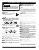
S-500 SERIES SUB. PUMP — SAFETY MESSAGE ALERT SYMBOLS FOR YOUR SAFETY AND THE SAFETY OF OTHERS! Safety precautions should be followed at all times when operating this equipment. Failure to read and understand the Safety Messages and Operating Instructions could result in injury to yourself and others. NOTE This Owner's Manual has been developed to provide complete instructions for the safe and efficient operation of the Multiquip Model S-500 Series Submersible Pumps.
S-500 SERIES SUB. PUMP — RULES FOR SAFE OPERATION CAUTION Failure to follow instructions in this manual may lead to serious injury or even death! This equipment is to be operated by trained and qualified personnel only! This equipment is for industrial use only. The following safety guidelines should always be used when operating the S- 500 Series Submersible Pumps: GENERAL SAFETY ■ DO NOT operate or servicing this equipment before reading this entire manual.
S-500 SERIES SUB. PUMP ■ ALWAYS make sure that electrical circuits are properly grounded per the National Electrical Code (NEC) and local codes before operating pump. Severe injury or death by electrocution can result from operating an ungrounded pump. — RULES FOR SAFE OPERATION . Emergencies ■ ALWAYS know the location of the nearest fire extinguisher. ■ NEVER use this pump to remove water from a swimming pool when people are in the water.
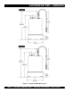
S-500 SERIES SUB. PUMP — DIMENSIONS Figure 1. S-500P, S-500UL Dimensions PAGE 8 — S-500 SERIES SUBMERSIBLE PUMPS — OPERATION & PARTS MANUAL — REV.
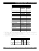
S-500 SERIES SUB. PUMP — SPECIFICATIONS TABLE 1. SPECIFICATIONS Model S-500P S-500UL Type Centrifugal Submersible Pump Centrifugal Submersible Pump Rubber Rubber Impeller Suction & Discharge Size 2.00 in. (51 mm) Maximum Pumping Capacity 61 gallons/minute (230 liters/minute) 63 gallons/minute (238 liters/minute) N/A N/A 34 ft. (10.4 meters) 36 ft (11.0 meters) 0.5 HP (0.37kw) 0.5 HP (0.37kw) Voltage Phase 1Ø 115V 1Ø 115V Starting Amps 50.4 44.1 Running Amps 7.2 6.
S-500 SERIES SUB. PUMP — GENERAL INFORMATION Introduction The Multiquip Model S-500 series submersible pumps are designed to pump water and is used for the draining (dewatering) of swimming pools, well casings construction sites, cofferdams, manholes, transformer vaults and excavations. A rubber type impeller is attached to the output shaft of a 0.5 HP electric motor which provides adequate power for general purpose pumping.
S-500 SERIES SUB. PUMP — COMPONENTS Figure 2. Submersible Pump Components Figure 2 shows the location of the basic components, for the S-500 series submersible pumps. Listed below is a brief explanation of each component. 1. Strainer Base – This strainer base is made of stainless steel which is resistant to hardware corrosion. DO NOT pump large objects or debris with this pump. This pump is for pumping water only. For de-watering purposes, always place the strainer base on a platform. 6.
S-500 SERIES SUB. PUMP — FLOAT SWITCHES Float Switch Theory Design Features Mercury monitoring is a mercury-switch actuated, liquid level control that has proven to be more economical and longer lasting than other types of liquid-level control systems, easily replacing and improving upon diaphragm switches, air bubble systems and electromechanical switches most often relied upon in the past. Constructed of rigid, durable ABS polymer ultrasonically welded.
S-500 SERIES SUB. PUMP — FLOAT SWITCH (PIGGY-BACK) Float Switch Single or dual control float switches can be used for the unattended operation of the submersible pump. When using the piggyback power configuration (plug), the S-500 series pumps DO NOT require the use of a control box. In this configuration (piggy-back), the SW-1 (single float switch) or SW-2 (dual float switch) are required. Figure 6 is an example of a single float switch application. Mounting The Float Switch 1.
S-500 SERIES SUB. PUMP — FLOAT SWITCH (CONTROL BOX) Control Box (CB3) For special remote pumping applications of the submersible pump, a control box (Model CB3) may be required. This water resistant control box provides watertight housing and glands to prevent water from leaking into the box, and a float switch interface. When using the CB3 control box, only the SW-1WOP float switch (2) can be used (no plug, bare wires). Shown below (Figure 7) is a wiring layout of the CB3 control box.
S-500 SERIES SUB. PUMP — OPERATION Hose Connections 1. Connect a 2-inch hose to the discharge port on the pump as shown in Figure 8. Make sure that the hose is attached correctly to the discharge port. Pump Power Connections (Piggy-Back Cord Only) 1. Make sure the circuit breaker supplying power to the pump is in the OFF position. 2. Connect the float switch or switches to the AC power receptacle as shown in Figure 6. Attaching Lifting Rope 1.
S-500 SERIES SUB. PUMP— CONTROL BOX INSTALLATION DANGER The S-500 series submersible pumps are also designed to work with a control box (Model CB3). This control box contains the necessary electronics (float switch connections) to operate the pump. Remember this control box contains hazardous voltages. Disconnect all sources of power before installing or servicing.
S-500 SERIES SUB. PUMP— CONTROL BOX INSTALLATION Connecting AC Power to the Control Box 1. 2. 3. The AC power cord (input) should have three wires. Each wire is color coded. The colors are WHITE, BLACK and GREEN. Remove the AC input connector housing from the control box, then route the power cord through the cable gland on the control box. Connect the AC power cord to the contactor as shown in Figure 7 and Table 6. 2.
S-500 SERIES SUB. PUMP — CLEAN-UP Pump Shut-Down/Clean-up 1. Remove the power from the pump by turning off the circuit breaker or switch that provides power to the pump. Remember to make sure that hands are dry (not wet), and feet are not standing in water when removing disconnecting power from the pump. 2. Using the lifting rope, lift the pump up from its current position. Remove the discharge hose from the discharge port on the pump. 3. Remove all power cables and float switches from the control box.
S-500 SERIES SUB. PUMP — MAINTENANCE LUBRICATION To check the oil level of the mechanical seal perform the following: DISASSEMBLY Refer to Figure 11 for location of parts to be removed. 2. While checking the hydraulic oil level, also check the condition of the hydraulic oil in the seal cavity . Block the opening with a finger and roll pump to one side to drain oil into a small transparent container. If oil is cloudy or has water in it, drain oil from pump cavity and replace hydraulic oil.
S-500 SERIES SUB. PUMP — TROUBLESHOOTING Practically all breakdowns can be prevented by proper handling and maintenance inspections, but in the event of a breakdown, use Table 8 (Pump Troubleshooting) as a basic guideline for troubleshooting the pump. If the problem cannot be remedied, contact Multiquip's service department. TABLE 8. PUMP TROUBLESHOOTING SYMPTOM POSSIBLE PROBLEM SOLUTION Incorrect voltage/amps? Check that proper voltage (115 VAC, 60 Hz, single-phase ) is being supplied to the pump.
S-500 SERIES SUB. PUMP — PERFORMANCE CURVES Total Head ( ft ) ST-500UL Performance Curve 60 TOTAL HEAD Max 3536 FT CAPACITY Max 63 G.P.M G 40 20 0 0 10 20 30 40 50 Capacity(US.G.P.M) Quantity (G.P.M) Total Head ( ft ) ST-500P Performance Curve 60 Max 34 FT CAPACITY Max 61 G.P.M G 40 20 0 0 TOTAL HEAD 10 20 30 Capacity(US.G acity(US.G.P.M) Quantity (G.P.M) Figure 12. Pump Performance Curves S-500 SERIES SUBMERSIBLE PUMPS — OPERATION & PARTS MANUAL — REV.
S-500 SERIES SUB. PUMP — WIRING DIAGRAMS 115 VAC, 60 Hz. ELECTRIC MOTOR WIRING DIAGRAM LEAD WIRES U V AC POWER CORD MAIN COIL BLACK (LINE) WHITE (NEUTRAL) AUXILIARY COIL GREEN (GROUND) CENTRIFUGAL SWITCH CONTROL BOX WIRING DIAGRAM CONTACTOR PUMP POWER CORD SUBMERSIBLE PUMP BLACK WHITE GREEN WHITE T1 INPUT POWER CORD L1 BLACK COIL EXTERNAL 1-PHASE (115 VAC, 60 Hz.) POWER SOURCE CIRCUIT BREAKER L1 L2 GND BLACK WHITE GREEN GREEN POWER ON LAMP T2 CHASSIS GND.
NOTE PAGE S-500 SERIES SUBMERSIBLE PUMPS — OPERATION & PARTS MANUAL — REV.
S-500 SERIES SUB. PUMP — EXPLANATION OF CODE IN REMARKS COLUMN How to read the marks and remarks used in this parts book. NOTE Items Found In the “Remarks” Column T he contents of this parts catalog are subject to change without notice. Serial Numbers-Where indicated, this indicates a serial number range (inclusive) where a particular part is used. Model Number-Where indicated, this shows that the corresponding part is utilized only with this specific model number or model number variant.
S-500 SERIES SUB. PUMP — SUGGESTED SPARE PARTS S-500P/UL SUBMERSIBLE PUMP 1 TO 3 UNITS Qty. P/N Description 1 ............ 020S500UL120 .............. AC CORD W/ GLAND 1 ............ 020S500UL060 .............. MECHANICAL SEAL 1 ............ 020S500UL074 .............. PACKING 1 ............ 0202S500UL214 ............ PACKING 1 ............ 020S500UL003 .............. IMPELLER S-500 SERIES SUBMERSIBLE PUMPS — OPERATION & PARTS MANUAL — REV.
S-500P/UL/CE — ELECTRIC SUBMERSIBLE PUMP ASSY. S-500P, S-500UL, S-500CE SUBMERSIBLE PUMP ASSY. 444 7 67 127 265 34 125 431 65 102 895 120 121 103 893 894 829 174 3 829 53 5 214 4 170 1 224 119 238 264 146 891 74 60 918 302 300 299 PAGE 26 — S-500 SERIES SUBMERSIBLE PUMPS — OPERATION & PARTS MANUAL — REV.
S-500P/UL/CE — ELECTRIC SUBMERSIBLE PUMP ASSY. S-500P, S-500UL, S-500CE SUBMERSIBLE PUMP ASSY. NO 1 3 3 4 5 7 34 53 60 65 67 74 102 102 102 103 119 119 120 120 121 125 125 PART NO 020S500UL001 020S500UL003 020S500CE003 020S500UL004 020S500UL005 020S500UL007 020S500UL034 020S500UL053 020S500UL060 020S500UL065 020S500UL067 020S500UL074 020S500CE102 020S500P102 020S500UL02 020S500UL103 020S500UL119 020S500CE119 020S500UL120 020S500CE120 020S500UL121 020S500UL125 020S500CE125 PART NAME QTY.
S-500P/UL/CE — ELECTRIC SUBMERSIBLE PUMP ASSY. S-500P, S-500UL, S-500CE SUBMERSIBLE PUMP ASSY. 444 7 67 127 265 34 125 431 65 102 895 120 121 103 893 894 829 174 3 829 53 5 214 4 170 1 224 119 238 264 146 891 74 60 918 302 300 299 PAGE 28 — S-500 SERIES SUBMERSIBLE PUMPS — OPERATION & PARTS MANUAL — REV.
S-500P/UL/CE — ELECTRIC SUBMERSIBLE PUMP ASSY. S-500P, S-500UL, S-500CE SUBMERSIBLE PUMP ASSY.
S-500P/UL — ELECTRIC MOTOR ASSY. S-500P/UL ELECTRIC MOTOR ASSY. PAGE 30 — S-500 SERIES SUBMERSIBLE PUMPS — OPERATION & PARTS MANUAL — REV.
S-500P/UL — ELECTRIC MOTOR ASSY. S-500P/UL ELECTRIC MOTOR ASSY. NO 156* 157-1* 157-2* 158* 270* 273* 400* 445* 446* 567* A PART NO 020S500UL156 020S500UL1571 020S500UL1572 020S500UL158 020S500UL270 020S500UL273 020S500UL400 020S500UL445 020S500UL446 020S500UL567 020S500UL119 PART NAME QTY. REMARK MOTOR HEAD COVER 1 HEAD COVER PACKING A 1 HEAD COVER PACKING B 1 BOLT 4 MOTOR ROTOR 1 MOTOR STATOR 1 SPRING WASHER 4 CAPACITOR 1 AUTO-CUT (PROTECTOR) 1 WASHER 4 MOTOR ASSEMBLY ..................... 1.............
S-500CE — ELECTRIC MOTOR ASSY. S-500CE ELECTRIC MOTOR ASSY. PAGE 32 — S-500 SERIES SUBMERSIBLE PUMPS — OPERATION & PARTS MANUAL — REV.
S-500CE — ELECTRIC MOTOR ASSY. S-500CE ELECTRIC MOTOR ASSY. NO 156* 157-1* 157-2* 158* 270* 273* 400* 445* 446* 567* A PART NO 020S500UL156 020S500CE1571 020S500CE1572 020S500UL158 020S500UL270 020S500CE273 020S500UL400 020S500CE445 020S500CE446 020S500UL567 020S500CE119 PART NAME QTY. REMARK MOTOR HEAD COVER 1 HEAD COVER PACKING A 1 HEAD COVER PACKING B 1 BOLT 4 MOTOR ROTOR 1 MOTOR STATOR 1 SPRING WASHER 4 CAPACITOR 1 AUTO-CUT (PROTECTOR) 1 WASHER 4 MOTOR ASSEMBLY ..................... 1.................
Effective: October 1, 2002 PAYMENT TERMS TERMS AND CONDITIONS OF SALE — PARTS 5. Parts must be in new and resalable condition, in the original Multiquip package (if any), and with Multiquip part numbers clearly marked. 6. The following items are not returnable: Terms of payment for parts are net 10 days. FREIGHT POLICY All parts orders will be shipped collect or prepaid with the charges added to the invoice. All shipments are F.O.B. point of origin.
NOTE PAGE S-500 SERIES SUBMERSIBLE PUMPS — OPERATION & PARTS MANUAL — REV.
OPERATION AND PARTS MANUAL HERE'S HOW TO GET HELP PLEASE HAVE THE MODEL AND SERIAL NUMBER ON-HAND WHEN CALLING MULTIQUIP CORPORATE OFFICE 18910 Wilmington Ave. Carson, CA 90746 Email: mq@multiquip.com Internet: www.multiquip.com PARTS DEPARTMENT 800-427-1244 310-537-3700 MAYCO PARTS 800-306-2926 310-537-3700 SERVICE DEPARTMENT 800-421-1244 310-537-3700 TECHNICAL ASSISTANCE 800-478-1244 WARRANTY DEPARTMENT 800-421-1244, EXT. 279 310-537-3700, EXT.