Operation and Parts Manual MODEL gaC-6HZ portable generator (HONDA GX340 GASOLINE ENGINE) Revision #1 (03/31/10) To find the latest revision of this publication, visit our website at: www.multiquip.com THIS MANUAL MUST ACCOMPANY THE EQUIPMENT AT ALL TIMES.
Table of Contents GAC6HZ Portable 60 Hz Generator Table Of Contents..................................................... 2 Parts Ordering Procedures....................................... 3 Safety Information................................................. 4-8 Specifications (Generator)...................................... 12 Specifications (Engine)........................................... 11 Dimensions............................................................. 12 Installation.......................
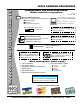
www.multiquip.com parts ordering procedures Ordering parts has never been easier! Choose from three easy options: Order via internet (dealers Only): Best deal! Effective: January 1st, 2006 If you have an MQ Account, to obtain a Username and Password, E-mail us at: parts@multiquip. com. Order parts on-line using Multiquip’s SmartEquip website! ■ View Parts Diagrams ■ Order Parts ■ Print Specification Information To obtain an MQ Account, contact your District Sales Manager for more information.
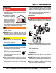
Safety Information Do not operate or service the equipment before reading the entire manual. Safety precautions should be followed at all times when operating this equipment. Failure to read and understand the safety messages and operating instructions could result in injury to yourself and others. Potential hazards associated with the operation of this equipment will be referenced with hazard symbols which may appear throughout this manual in conjunction with safety messages.
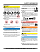
Safety Information geNeRal saFeTY CauTiON NeveR operate this equipment without proper protective clothing, shatterproof glasses, respiratory protection, hearing protection, steel-toed boots and other protective devices required by the job or city and state regulations. NeveR operate this equipment when not feeling well due to fatigue, illness or when under medication. NeveR operate this equipment under the influence of drugs or alcohol.
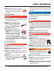
Safety Information eNgiNe saFeTY daNgeR The engine fuel exhaust gases contain poisonous carbon monoxide. This gas is colorless and odorless, and can cause death if inhaled. The engine of this equipment requires an adequate free flow of cooling air. NeveR operate this equipment in any enclosed or narrow area where free flow of the air is restricted. If the air flow is restricted it will cause injury to people and property and serious damage to the equipment or engine.
Safety Information NeveR use fuel as a cleaning agent. dO NOT smoke around or near the equipment. Fire or explosion could result from fuel vapors or if fuel is spilled on a hot engine. eleCTRiCal saFeTY daNgeR Make sure power cables are securely connected to the generator’s output receptacles. Incorrect connections may cause electrical shock and damage to the generator. NOTICE alWaYs make certain that proper power or extension cord has been selected for the job.
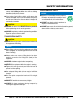
Safety Information If the battery liquid (dilute sulfuric acid) comes into contact with clothing or skin, rinse skin or clothing immediately with plenty of water. eNviRONmeNTal saFeTY If the battery liquid (dilute sulfuric acid) comes into contact with eyes, rinse eyes immediately with plenty of water and contact the nearest doctor or hospital to seek medical attention. Dispose of hazardous waste properly. Examples of potentially hazardous waste are used motor oil, fuel and fuel filters.
NOTES GAC-6HZ 60 hz GENERATOR • operation and parts manual — rev.
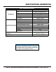
SPECIFICATIONS (gENERATOR) Table 1. Specifications (Generator) Model Type Excitation AC Generator Speed Cooling System Fuel Capacity Continuous Power Output Max Power Output Rated Voltage Current Max/Continuous (120V) 60 Hz AC Power Source Current Max/Continuous (240V) Phase Frequency Power Factor Dimensions (L x W x H) Dry Net Weight GAC6HZ Brushless Revolving Field Type Solid State, Statically Excited System 3,600 RPM Self-Ventilation 5 gallons (19 liters) 5.0 kW 6.0 kW 120/240V 50.0/41.6 amps 25.0/20.
SPECIFICATIONS (engine) Engine Dimensions (L x W x H) Dry Net Weight Table 2. Specifications (Engine) HONDA GX340K1EDE2 Model HONDA GX340U1EDE2 Air-cooled 4 stroke, Single Cylinder, OHV, Type Horizontal Shaft Gasoline Engine 3.23 in. X 2.52 in. Bore X Stroke (82 mm x 64 mm.) Displacement 20.63 cu-in (389 cm3) Max Output 11.0 H.P./3600 R.P.M. Fuel Unleaded Automobile Gasoline Lube Oil Capacity 1.16 quarts (1.
dimensions 6000 18.9 IN (480 MM.) 30.70 IN (780 MM.) GAC-6HZ 120 POWERED by 211052 V 240 Honda Engines AC VOLTMETER VOLTOMETRE CA OFF MARCHE ON MARCHE ON 240V ARRET OFF OFF ARRET AC CIRCUIT IDLE OPERATION GFCI CIRCUIT BREAKER CONTROL SWITCH BREAKER (for main) INTERRUPTEUR INTERRUPTEUR DE INTERRUPTEUR DE CONTROL DE RALENTI COURANT DE OPERATION COURANT PRINCIPAL START BUTTON BOUTON DE DEMARRAGE 120V 20.27 IN (515 MM.) Figure 1.
note GAC-6HZ 60 hz GENERATOR • operation and parts manual — rev.
installation Connecting the Ground The nut and ground terminal on the generator should always be used to connect the generator to a suitable ground. The ground cable should be #8 size wire minimum. At the generator, connect the terminal of the ground cable between the lock washer and the nut (Figure 2) and tighten the nut fully. Connect the other end of the ground cable to a suitable earth ground (ground rod). Figure 2.
installation Outdoor Installation Generator Grounding If possible install the generator in a area that is free of debris, bystanders, and overhead obstructions. Make sure the generator is on secure level ground so that it cannot slide or shift around. To guard against electrical shock and possible damage to the equipment, it is important to provide a good EARTH ground. The installation site must be relatively free from moisture and dust.
general information FAMILIARIZATION Generator The Multiquip GAC6HZ generator is designed as a portable dual purpose power source for 60 Hz (single phase) lighting facilities, power tools, submersible pumps and other industrial and construction machinery. DANGER Before connecting this generator to any building’s electrical system, a licensed electrician must install an isolation (transfer) switch. Serious injury or death may result without this transfer switch.
components (generator) 1 2 3 5 6 4 9 7 8 GAC-6HZ 120 POWERED by 211052 V 240 Honda Engines AC VOLTMETER VOLTOMETRE CA OFF MARCHE ON MARCHE ON 240V ARRET OFF OFF ARRET AC CIRCUIT IDLE OPERATION GFCI CIRCUIT BREAKER CONTROL SWITCH BREAKER (for main) INTERRUPTEUR INTERRUPTEUR DE INTERRUPTEUR DE CONTROL DE RALENTI COURANT DE OPERATION COURANT PRINCIPAL START BUTTON BOUTON DE DEMARRAGE 120V 10 11 Figure 3. Generator Components 1.
components (generator) 15 GAC-6HZ 120 POWERED by 211052 V 240 Honda Engines 16 AC VOLTMETER VOLTOMETRE CA OFF MARCHE ON MARCHE ON 240V ARRET OFF OFF ARRET AC CIRCUIT IDLE OPERATION GFCI CIRCUIT BREAKER CONTROL SWITCH BREAKER (for main) INTERRUPTEUR INTERRUPTEUR DE INTERRUPTEUR DE CONTROL DE RALENTI COURANT DE OPERATION COURANT PRINCIPAL START BUTTON BOUTON DE DEMARRAGE 17 120V 12 13 14 20 18 19 21 22 Figure 4. Generator Components (continued) 12.
INSPECTION/SETUP General Inspection Prior to Operation Ground Power Tools When using power tools or electrical equipment requireing AC power from the generator, make sure power tool cord has a ground pin or is double insulated as shown in Figure 5. NOTICE Double-insulated power tools and small appliances have specially insulated housings that eliminate the need for a ground pin.
INSPECTION/SETUP Before Starting 1. Read safety instructions at the beginning of manual. 2. Clean the generator, removing dirt and dust, particularly the engine cooling air inlet, carburetor and air cleaner. 3. Check the air filter for dirt and dust. If air filter is dirty, replace air filter with a new one as required. 4. Check carburetor for external dirt and dust. Clean with dry compressed air. 5. Check fastening nuts and bolts for tightness Engine Oil Check Table 4.
operation This section is intended to assist the operator with the initial start-up of the portable generator. It is extremely important that this section be read carefully before attempting to use the generator in the field. 2. Place the choke lever (Figure 13) in the CLOSED position if starting a cold engine. Before Starting the Engine 1. Be sure to disconnect all electrical loads from the generator prior to starting the engine. 2. NEVER start the engine with the main circuit breaker in the ON position.
operation NOTICE DO NOT pull the starter rope all the way to the end. 10. Place main circuit breaker (Figure 19) in the ON position. DO NOT release the starter rope after pulling. Allow it to rewind as soon as possible.. 7. If the engine has started, slowly return the choke lever (Figure 13) to the OPEN position. If the engine has not started repeat steps 1 through 8. 8. Before the generator is placed into operation, run the engine for 3-5 minutes.
operation/shutdown 13. Read voltmeter on front panel of generator (Figure 22) and verify that 240 VAC is displayed. Using an external voltmeter as shown in Figure 20, verify that 240 VAC is present at the 240V twist-lock receptacle. 2. Place GFCI circuit breaker (Figure 24) in the OFF positing. Figure 24. GFCI Circuit Breaker (OFF) 3. Place idle control switch (Figure 25) in the OFF position. Figure 25. Idle Control switch (OFF) 4. Let engine run at idle with no load for 2-3 minutes. 5.
preparation for long term storage Generator Storage For storage of the generating set for over 30 days, the following is required: Drain the fuel tank completely, or add STA-BIL to the fuel. Run the engine until the gasoline in the carburetor is completely consumed. Completely drain the oil from the crankcase and refill with fresh oil. Remove the spark plug, pour 2 or 3 cc of SAE 30 oil into the cylinder and crank slowly to distribute the oil.
maintenance Use Table 5 as a general maintenance guideline when servicing your engine. For more detail engine maintenance information, refer to the engine owner's manual supplied with your engine. Table 5.
maintenance Maintenance Perform the scheduled maintenance procedures as defined by Table 5 and below: Daily Thoroughly remove dirt and oil from the engine and control area. Clean or replace the air cleaner elements as necessary. Check and retighten all fasteners as necessary. Weekly Remove the fuel filter cap and clean the inside of the fuel tank. Remove or clean the filter at the bottom of the tank. Remove and clean the spark plug (Figure 28), then adjust the spark gap to 0.024 ~0.028 inch (0.
generator wiring digram SYMBOL PART NAME Ar Armature Winding Fg-PN Field Winding EXW1~2 Excitation Winding V AC Voltmeter (120/240) Re1~3 Rectifier CON1 Receptacle L5-30R CON2 Receptacle L6-20R CON3 CB Wiring Color Code Symbol Color Symbol B BLACK R Color RED L BLUE W WHITE Receptacle 5-15R BR BROWN Y YELLOW UPM-2 20A G GREEN LB LIGHT BLUE CB1 CP-31E/15N 15A GR GRAY LG LIGHT GREEN SW1 Idle Control Switch V VIOLET O ORANGE SW2 Operation Switch P PINK SW3
troubleshooting (ENGINE) Table 6. Engine Troubleshooting Symptom Difficult to start. Fuel is available but no SPARK at spark plug. Difficult to start. Fuel is available and SPARK is present at the spark plug. Difficult to start. Fuel is available, SPARK is present at the spark plug and compression is normal. Difficult to start. Fuel is available, SPARK is present at the spark plug and compression is low. No fuel present at carburetor. Weak in power. Compression is proper and does not misfire.
troubleshooting (ENGINE) Table 6. Engine Troubleshooting (Continued) Symptom Possible Cause Solution Weak in power. Compression is proper but misfires. Water in fuel system? Flush fuel system and replace with correct type of fuel. Dirty spark plug? Clean or replace spark plug Ignition coil defective? Replace ignition coil. Spark plug heat value improper? Replace with correct type of spark plug. Incorrect type of fuel? Replace with correct type of fuel. Cooling fins dirty? Clean cooling fins.
troubleshooting (GENERATOR) Symptom Low voltage Low voltage. Engine speed normal 3650 RPM (unloaded), 2500 RPM (idle) Table 7. Generator Troubleshooting Possible Problem Solution Engine speed too low? Raise engine speed to rated RPM. AC voltmeter not working? Replace Ac voltmeter. Control box internal wiring Check control box wiring. malfunction? Check red and green ignition wires. Defective ignition coil? Replace ignition wires if necessary. Rotor winding malfunction? Check or replace rotor.
notes GAC-6HZ 60 hz GENERATOR • operation and parts manual — rev.
Explanation of Code in Remarks Column The following section explains the different symbols and remarks used in the Parts section of this manual. Use the help numbers found on the back page of the manual if there are any questions. NOTICE The contents and part numbers listed in the parts section are subject to change without notice. Multiquip does not guarantee the availability of the parts listed. sample paRTs lisT NO. 1 2% 2% 3 4 paRT NO. paRT Name QTY. RemaRKs 12345 BOLT......................1 .....
Suggested Spare Parts GAC6HZ portable 60 hZ generator with HONDA GX340K1EDE2/gx340u1ede2 gasoline engines 1 to 3 units Qty. P/N Description 1............0810106004...........CAP FUEL TANK 1............0810107103...........FILTER FUEL 1............3015419604...........rubber suspension 4............1725419214...........rubber suspension 3............9807955846...........SPARK PLUG 1♦..........15510ZE2043........SWITCH ASSY., OIL ALERT 1◊ .........15510ZE2053........SWITCH ASSY., OIL ALERT 1............
GAC6HZ— nameplate and decalS ASSY. S/N 5561048 AND BELOW Insulation System --- B Maximum ambient Temperature --- 40°C (104°F) Systéme d’insulation --- B Température ambiante maximum --- 40°C (104°F) 10 A33210030A 6000 8 CAUTION 7 Do not use in rain or snow. ATTENTION 1 Ne pas utiliser en cas de pluie ou neige. A3520000A FUEL COCK ROBINET’ D ESSENCE ON/OUVERT CAUTION/ATTENTION OFF/ FERMER HOT PARTS can burn skin. A90820000 DO NOT touch until the lamp has sufficiently cooled.
GAC6HZ— nameplate and decals ASSY. NO. PART NO. 1 A3552000004A 2 A6552000404A 3 A6532100904A 4 A6532101004A 5 A5552000804 6 A5552000704A 7 A9508200004 8 W7900631302 10 A3532100304A 11 A9511100204 12 A9504000104 13 A9504000204 14 A6532101104A 15 A6532101404 PART NAME QTY. REMARKS DECAL; CAUTION, RAIN SNOW........................1................A35200000A DECAL; CAUTION, HOT PARTS........................1................A65300040A DECAL; WARNING, EXHAUST GASES.............1................
GAC6HZ — GENERATOR ASSY. page 36 — GAC-6HZ 60 hz gENERATOR• operation and parts manual — rev.
GAC6HZ — GENERATOR ASSY. NO. PART NO. 1 7901002403 1-1# 1-2# 0601823213 0601822638 1-3# 0071706304 2 7901017004 3 0801086104 4 0040010000 5 A5136001103 6 7901315502 7 7871315022 8 7875021523 9 7871331003 10 7901316004 11 0040008000 12 0041208000 13 7871329514 14 0601851760 15 0013608020 15A 0040008000 PART NAME QTY. REMARKS ROTOR ASSY......................................................1................INCLUDES ITEMS W/# FIELD ASSY........................................................1................
GAC6HZ — CONTROL BOX ASSY. page 38 — GAC-6HZ 60 hz gENERATOR• operation and parts manual — rev.
GAC6HZ — CONTROL BOX ASSY. NO. 1 2 3 4 5 6 7 8 9 10 11 12 13 13A 14 15 16 17 18 19 20 21 22 23 24 25 26 27 27A 28 28A 28B 29 30 30A 30B 31 31A 32 32A PART NO.
GAC6HZ — MUFFLER ASSY. page 40 — GAC-6HZ 60 hz gENERATOR• operation and parts manual — rev.
GAC6HZ — MUFFLER ASSY. NO. 1 2 3 4 5 6 7 8 9 10 11 12 13 13A 14 15 16 17 PART NO. 7912310003 18320ZC2000 18325ZB4000 18329ZB4000 18335ZB4630 90183671003 0017106012 18333ZB4800 957000802000 7905461004 0017108020 7905469004 0017108025 0207008000 0017108020 7905469004 0017106020 0017106012 PART NAME QTY. REMARKS MUFFLER 1 PROTECTOR......................................................1................REPLACES P/N 0602302001 PROTECTOR......................................................1................
GAC6HZ — PIPE FRAME ASSY. page 42 — GAC-6HZ 60 hz gENERATOR• operation and parts manual — rev.
GAC6HZ — PIPE FRAME ASSY. NO. 1 2 3 4 5 6 7 8 8A 9 10 11 12 13 14 15 16 17 18 19 20 21 22 23 24 25 26 27 28 29 30 31 32 33 PART NO.
HONDA GX340K1/U1EDE2 — AIR CLEANER ASSY. page 44 — GAC-6HZ 60 hz gENERATOR• operation and parts manual — rev.
HONDA GX340K1/U1EDE2 — AIR CLEANER ASSY. NO. 1 2 3♦ 3◊ 3◊ 4♦ 4◊ 4◊ 5 6 7 8 9 10 11 12 13◊ PART NO. 15721ZB4000 17211899000 17212ZB4003 17212ZB4003 17212Z5R000 17220ZB4003 17220ZB4003 17220Z5R000 17222ZC2000 17231899000 17235899000 17236899000 17252899000 17367413690 9405005000 9405006000 17232898000 PART NAME QTY. REMARKS TUBE BREATHER 1 ELEMENT, AIR CLEANER 1 SEPARATOR, AIR CLEANER 1 SEPARATOR, AIR CLEANER.............................1................S/N 1157236 AND BELOW SEPARATOR, AIR CLEANER..........
HONDA GX340K1/U1EDE2 ENGINE — CAMSHAFT ASSY. page 46 — GAC-6HZ 60 hz gENERATOR• operation and parts manual — rev.
HONDA GX340K1/U1EDE2 ENGINE — CAMSHAFT ASSY. NO. PART NO. 1♦ 14100ZE3010 1♦ 14100ZE3020 1◊ 14100ZE3020 2 14410ZE3013 3♦ 14431ZE2010 3 14431ZE2010 4 14441ZE2000 5 14451ZE1013 6$ 14568ZE1000 7 14711ZE3000 8 14721ZE3000 9 14751ZE2003 10 14771ZE2000 11 14773ZE2000 12 14775ZE2010 13 14781ZE2000 14 14791ZE2010 15 90012ZE0010 16 90206ZE1000 17 12209ZE8003 PART NAME QTY. REMARKS CAMSHAFT ASSY..............................................1................S/N 2708026 AND BELOW . ...............................
HONDA GX340K1/U1EDE2 ENGINE — CARBURETOR ASSY. page 48 — GAC-6HZ 60 hz gENERATOR• operation and parts manual — rev.
HONDA GX340K1/U1EDE2 ENGINE — CARBURETOR ASSY. NO. PART NO. 1 16010ZE3701 2$ 16011ZA0931 3$ 16013ZA0931 4$ 16015ZA0931 5$ 16016ZH7W01 6♦$ 16024124761 7$ 16028ZA0931 8♦ 16100ZE3F10 PART NAME QTY. REMARKS GASKET SET 1 VALVE SET, FLOAT 1 FLOAT SET 1 CHAMBER SET, FLOAT 1 SCREW SET 1 SCREW SET, DRAIN 1 SCREW SET B 1 CARBURETOR ASSY., (BE82B A).....................1................USE S/N 2374606~2521477 . ............................................................................................
HONDA GX340K1/U1EDE2 ENGINE — CARBURETOR ASSY. page 50 — GAC-6HZ 60 hz gENERATOR• operation and parts manual — rev.
HONDA GX340K1/U1EDE2 ENGINE — CARBURETOR ASSY. NO. 18# 19# 20# 21# 22# 23# 24 25♦# 25◊ # 25◊ # 26# 27# 28# 29 30# 31 32# 33# 34# 35# 36 37# 38 39 40# 41# 42# 43# 44 45 46 47 47 47$ 48$ PART NO.
HONDA GX340K1/U1EDE2 ENGINE — CONTROL ASSY. page 52 — GAC-6HZ 60 hz gENERATOR• operation and parts manual — rev.
HONDA GX340K1/U1EDE2 ENGINE — CONTROL ASSY. NO. 1 3 4 5 9 19$ 23 24 30$ 33 PART NO. 16550ZE3700 16555ZE3000 16561ZE3000 16562ZE3700 16570ZE3700 16584883300 90013883000 90015ZE5010 93500050350A 9405006000 PART NAME QTY. REMARKS ARM, GOVERNOR 1 ROD, GOVERNOR 1 SPRING, GOVERNOR 1 SPRING, THROTTLE RETURN 1 CONTROL ASSY.................................................1................
HONDA GX340K1/U1EDE2 ENGINE — CRANKCASE COVER ASSY. page 54 — GAC-6HZ 60 hz gENERATOR• operation and parts manual — rev.
HONDA GX340K1/U1EDE2 ENGINE — CRANKCASE COVER ASSY. NO. 2♦ 2◊ 3 4 5 6% 7$ 8#$ 9#$ 10#$ 11♦$ 11♦$ 11◊ $ 12$ 13 14$ 15# 16 17$ 18$ PART NO. 11300ZE3020 11300ZE3040 11381ZE3801 15600ZG4003 15600735003 15625ZE1003 16510ZE3000 16511ZE8000 16512ZE3000 16513ZE2000 16531ZE2000 16531ZOA000 16531ZOA000 90602ZE1000 90701HC4000 92102ZE3004 9410106800 957010804000 961006202000 961006207000 PART NAME QTY. REMARKS COVER ASSY., CRANKCASE (S-TYPE)............1................INCLUDES ITEMS W/$ COVER ASSY.
HONDA GX340K1/U1EDE2 ENGINE — CRANKSHAFT ASSY. page 56 — GAC-6HZ 60 hz gENERATOR• operation and parts manual — rev.
HONDA GX340K1/U1EDE2 ENGINE — CRANKSHAFT ASSY. NO. 1♦ 1◊ 2 5# PART NO. 13310ZE3701 13310ZE3702 13351ZE3010 961006207000 PART NAME QTY. REMARKS CRANKSHAFT COMP.........................................1................INCLUDES ITEM W/# CRANKSHAFT COMP.........................................1................INCLUDES ITEM W/# WEIGHT, BALANCER 1 BEARING, RADIAL BALL (6207) 1 ♦GX340K1EDE2: Model GAC6HZ AUG. 2007 AND BELOW ◊ GX340U1EDE2: Model GAC6HZ JAN.
HONDA GX340K1/U1EDE2 ENGINE — CYLINDER BARREL ASSY. page 58 — GAC-6HZ 60 hz gENERATOR• operation and parts manual — rev.
HONDA GX340K1/U1EDE2 ENGINE — CYLINDER BARREL ASSY. NO. 1♦ 1◊ 2♦ 2◊ 2◊ 3 4 5 6 7 8$ 9$ 10 11 12 13 14 15$ 16 PART NO. 12000ZE3827 12000ZE3417 15510ZE2043 15510ZE2043 15510ZE2053 16541ZE3010 31161ZE2000 90013883000 90131883000 90446KE1000 91201ZE3004 91203952771 91353671004 9405010000 9410912000 9425110000 957010601200 961006202000 84150ZH7003 PART NAME QTY. REMARKS CYLINDER ASSY. (ALERT)................................1................INCLUDES ITEMS W/$ CYLINDER ASSY. (ALERT)..............................
HONDA GX340K1/U1EDE2 ENGINE — CYLINDER HEAD ASSY. page 60 — GAC-6HZ 60 hz gENERATOR• operation and parts manual — rev.
HONDA GX340K1/U1EDE2 ENGINE — CYLINDER HEAD ASSY. NO. 1♦ 1◊ 2 3$ 4$ 5 6 8 10 11 12 13 14 15 16 16 PART NO. 12200ZF6W01 12200ZF6W01 12204ZE2306 12205ZE2305 12216ZE2300 12251ZE3W00 12310ZE2020 12391ZE2020 90014ZE2000 90042ZE3700 92900080320E 90441ZE2010 9430112200 957011008000 9807955846 9807955855 PART NAME QTY. REMARKS CYLINDER HEAD...............................................1................INCLUDES ITEMS W/$ CYLINDER HEAD...............................................1................
HONDA GX340K1/U1EDE2 ENGINE — FAN cover ASSY. page 62 — GAC-6HZ 60 hz gENERATOR• operation and parts manual — rev.
HONDA GX340K1/U1EDE2 ENGINE — FAN cover ASSY. NO. 2 3 6 7 8 PART NO. 19610ZE3700ZB 19631ZE3W00 81329567020 90013883000 90654SA4003 PART NAME COVER, FAN *NH1* (BLACK) SHROUD GROMMET, DRAIN HOLE BOLT, FLANGE (6X12) (CT200) CLIP, WIRE HARNESS (6MM) (WHITE) QTY. 1 1 1 6 2 REMARKS GAC-6HZ 60 hz GENERATOR • operation and parts manual — rev.
HONDA GX340K1/U1EDE2 ENGINE — FLYWHEEL ASSY. page 64 — GAC-6HZ 60 hz gENERATOR• operation and parts manual — rev.
HONDA GX340K1/U1EDE2 ENGINE — FLYWHEEL ASSY. NO. 1 2 3 4♦ 4♦ 4◊ 4◊ 5 PART NO. 19511ZE3000 28451ZE3W01 31100ZE3722 90201ZE3790 90201ZE3V00 90201ZE3V00 90201ZE3790 90741ZE2000 PART NAME QTY. REMARKS FAN, COOLING 1 PULLEY, STARTER 1 FLYWHEEL COMP., (LAMP) 1 NUT, SPECIAL 16MM.........................................1................USE UP TO S/N 2536522 NUT, SPECIAL 16MM.........................................1................USE FROM S/N 2536523 NUT, SPECIAL 16MM.........................................1...
HONDA GX340K1/U1EDE2 ENGINE — IGNITION COIL ASSY. page 66 — GAC-6HZ 60 hz gENERATOR• operation and parts manual — rev.
HONDA GX340K1/U1EDE2 ENGINE — IGNITION COIL ASSY. NO. 1♦ 1◊ 2 3 3 6 7 10 11 12 13 15 PART NO. 30500ZE2023 30500ZF6W03 30700ZE1013 31510ZE1811 31510ZE3003 31511ZE3000 31512ZE2000 36101ZE3800 36103ZE1000 90012888000 90013883000 90015883000 PART NAME COIL ASSY., IGNITION COIL ASSY., IGNITION CAP ASSY., NOISE SUPPRESSOR COIL ASSY., LAMP (12V/25W) COIL ASSY.
HONDA GX340K1/U1EDE2 ENGINE — PISTON ASSY. page 68 — GAC-6HZ 60 hz gENERATOR• operation and parts manual — rev.
HONDA GX340K1/U1EDE2 ENGINE — PISTON ASSY. NO. 1♦ 1◊ 1♦ 1◊ 1♦ 1◊ 1♦ 1◊ 2♦ 2♦ 2♦ 2♦ 2◊ 2◊ 2◊ 2◊ 3 4 5$ 6 PART NO. 13010ZE3003 13010Z5L004 13011ZE3003 13011ZE5L004 13012ZE3003 13012ZE5L004 13013ZE3003 13013ZE5L004 13101ZE3W00 13102ZE3W00 13103ZE3W00 13104ZE3W00 13101ZE3W01 13102ZE3W01 13103ZE3W01 13104ZE3W01 13111ZF6000 13200ZE3020 90001ZE8000 90601ZE3000 PART NAME QTY. REMARKS RING SET, PISTON (STD) 1 RING SET, PISTON (STD) 1 RING SET, PISTON (OS 0.25) (OPTIONAL) 1 RING SET, PISTON (OS 0.
HONDA GX340K1/U1EDE2 ENGINE — RECOIL STARTER ASSY. page 70 — GAC-6HZ 60 hz gENERATOR• operation and parts manual — rev.
HONDA GX340K1/U1EDE2 ENGINE — RECOIL STARTER ASSY. NO. 1 2$ 3$ 4$ 5$ 6$ 7$ 8$ 9♦$ 10♦$ 10♦$ 10◊ $ 10◊ $ 11$ 13$ 14 PART NO. 28400ZE3W01ZB 28410ZE3W01ZB 28421ZE3W01 28422ZE2W01 28441ZE2W01 28442ZE2W01 28443ZE2W01 28444ZE2W01 28445ZE2W01 28461ZE2W01 28461ZE2W02 28461ZE2W02 28461ZE2W03 28462ZE3W01 90004ZE2W01 90008ZE2003 PART NAME QTY. REMARKS STARTER ASSY., RECOIL *NH1* (BLACK).......1................
HONDA GX340K1/U1EDE2 ENGINE — SOLENOID ASSY. page 72 — GAC-6HZ 60 hz gENERATOR• operation and parts manual — rev.
HONDA GX340K1/U1EDE2 ENGINE — SOLENOID ASSY. NO. 1 2 3♦ 3◊ 3◊ 4 5 PART NO. 16268893000 17850ZD1E30 36160ZB4003 36160ZB4003 36160ZB4013 90013883000 93500050080A PART NAME QTY. REMARKS SPRING, CHOKE RETURN 1 LEVER, THROTTLE 1 SOLENOID ASSY. 1 SOLENOID ASSY................................................1................USE UP TO S/N 1135653 SOLENOID ASSY................................................1................
HONDA GX340K1/U1EDE2 ENGINE — Starter motor ASSY. page 74 — GAC-6HZ 60 hz gENERATOR• operation and parts manual — rev.
HONDA GX340K1/U1EDE2 ENGINE — Starter motor ASSY. NO. PART NO. 1# 31204ZA0003 2# 31206ZE3003 3# 31207ZE3003 4♦# 31201ZE3013 4◊ # 31201ZE3013 4◊ # 31201ZE3023 5# 31211ZE2003 6# 31212ZE3003 7% 31213ZE2003 8# 31215ZE2003 9# 31218ZE3003 10# 31219ZE2003 11% 31222ZE3791 12# 31231ZE2003 13# 31232ZE3003 14# 31233ZE2003 15# 90110ZE2003 16# 91601ZE2003 17# 90007ZE2003 18# 938920503218 19# 9407206080 20 957010803508 PART NAME QTY. REMARKS CONTACTOR ASSY, 1 ARMATURE COMP 1 CLUTCH COMP, OVER RUNNING..............
HONDA GX340K1/U1EDE2 ENGINE — FUEL COCK ASSY. page 76 — GAC-6HZ 60 hz gENERATOR• operation and parts manual — rev.
HONDA GX340K1/U1EDE2 ENGINE — FUEL COCK ASSY. NO. 1# 2 3# 4#% 5# 6# 7 8 9♦ 9◊ PART NO. 16173001004 16950ZB4015 16952ZB4005 16958397771 16959471831 16967GA6671 90854ZB2000 950014519040 9500202080 950024080008 PART NAME QTY. REMARKS PACKING, FUEL STRAINER CUP 1 COCK ASSY., FUEL...........................................1................INCLUDES ITEMS W/# SCREEN, FUEL STRAINER...............................1................
HONDA GX340K1/U1EDE2— ENGINE DECALS ASSY. page 78 — GAC-6HZ 60 hz gENERATOR• operation and parts manual — rev.
HONDA GX340K1/U1EDE2— ENGINE DECALS ASSY. NO. 1 2♦ 2◊ 2◊ 3♦ 3◊ 3◊ 4 5◊ 5◊ 5◊ 5◊ PART NO. 87533ZC0630 87528898620 87528ZH7000 87528898620 87521ZE2W02 87521ZE2W03 87521ZE2W04 87594ZB4A00 87516ZH7000 87516ZH7010 87516ZH7800 87519ZH7801 PART NAME QTY. REMARKS DECAL, AIR CLEANER 1 DECAL, CHOKE 1 DECAL, CHOKE (GRAY) 1 DECAL, CHOKE.................................................1................USE FROM S/N 1100778 EMBLEM (GX240 HONDA 8.0) 1 EMBLEM (GX240 HONDA 8.0)..........................1................
HONDA GX340K1/U1EDE2 ENGINE — TOOL KIT page 80 — GAC-6HZ 60 hz gENERATOR• operation and parts manual — rev.
HONDA GX340K1/U1EDE2 ENGINE — TOOL KIT NO. 1 2# 3# 4# 5# 6# PART NO. 89000ZE1000 89218ZE1000 89219805000 9900110120 9900114170 9900802300 PART NAME QTY. REMARKS TOOL KIT............................................................1................INCLUDES ITEMS W/# WRENCH COMP. (SPARK PLUG) 1 HANDLE, BOX WRENCH 1 SAPNNER, 10X12 1 SAPNNER, 14X17 1 BAG TOOL 1 GAC-6HZ 60 hz GENERATOR • operation and parts manual — rev.
Terms and Conditions of Sale — Parts paYmeNT TeRms 5. Parts must be in new and resalable condition, in the original Multiquip package (if any), and with Multiquip part numbers clearly marked. 6. The following items are not returnable: Multiquip reserves the right to quote and sell direct to Government agencies, and to Original Equipment Manufacturer accounts who use our products as integral parts of their own products. a. speCial eXpediTiNg seRviCe Terms of payment for parts are net 30 days.
notes GAC-6HZ 60 hz GENERATOR • operation and parts manual — rev.
Operation and Parts Manual HERE’S HOW TO GET HELP PLEASE HAVE THE MODEL AND SERIAL NUMBER ON-HAND WHEN CALLING UNITED STATES Multiquip Corporate Office 18910 Wilmington Ave. Carson, CA 90746 Contact: mq@multiquip.com MQ Parts Department Tel. (800) 421-1244 Fax (800) 537-3927 Mayco Parts 800-427-1244 310-537-3700 Fax: 800-672-7877 Fax: 310-637-3284 Warranty Department 800-306-2926 310-537-3700 Fax: 800-672-7877 Fax: 310-637-3284 Service Department 800-421-1244, Ext. 279 310-537-3700, Ext.