OPERATION AND PARTS MANUAL WHISPERWATT™ SERIES MODEL DCA45SSIU3 50HZ GENERATOR (ISUZU BB-4JG1T DIESEL ENGINE) PARTS LIST NO. M1870300904 Revision #2 (12/19/08) To find the latest revision of this publication, visit our website at: www.mqpower.com THIS MANUAL MUST ACCOMPANY THE EQUIPMENT AT ALL TIMES.
PROPOSITION 65 WARNING Diesel engine exhaust and some of PAGE 2 — DCA45SSIU3 50 HZ GENERATOR • OPERATION AND PARTS MANUAL — REV.
REPORTING SAFETY DEFECTS If you believe that your vehicle has a defect that could cause a crash or could cause injury or death, you should immediately inform the National Highway Traffic Safety Administration (NHTSA) in addition to notifying Multiquip at 1-800-421-1244. If NHTSA receives similar complaints, it may open an investigation, and if it finds that a safety defect exists in a group of vehicles, it may order a recall and remedy campaign.
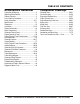
TABLE OF CONTENTS DCA45SSIU3 Generator Component Drawings Proposition 65 Warning ........................................... 2 Reporting Safety Defects......................................... 3 Table of Contents..................................................... 4 Parts Ordering Procedures ...................................... 5 Safety Information .............................................. 6-11 Specifications ........................................................ 12 Dimensions .................
www.mqpower.com PARTS ORDERING PROCEDURES Ordering parts has never been easier! Choose from three easy options: Effective: January 1st, 2006 Order via Internet (Dealers Only): Best Deal! If you have an MQ Account, to obtain a Username and Password, E-mail us at: parts@multiquip.com. Order parts on-line using Multiquip’s SmartEquip website! ■ View Parts Diagrams ■ Order Parts ■ Print Specification Information To obtain an MQ Account, contact your District Sales Manager for more information.
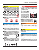
SAFETY INFORMATION Do not operate or service the equipment before reading the entire manual. Safety precautions should be followed at all times when operating this equipment. Failure to read and understand the safety messages and operating instructions could result in injury to yourself and others. Potential hazards associated with the operation of this equipment will be referenced with hazard symbols which may appear throughout this manual in conjunction with safety messages.
SAFETY INFORMATION GENERAL SAFETY CAUTION NEVER operate this equipment without proper protective clothing, shatterproof glasses, respiratory protection, hearing protection, steel-toed boots and other protective devices required by the job or city and state regulations. NEVER operate this equipment when not feeling well due to fatigue, illness or when under medication. NEVER operate this equipment under the influence of drugs or alcohol.
SAFETY INFORMATION ENGINE SAFETY WARNING DO NOT place hands or fingers inside engine compartment when engine is running. NEVER operate the engine with heat shields or guards removed. Keep fingers, hands hair and clothing away from all moving parts to prevent injury. DO NOT remove the radiator cap while the engine is hot. High pressure boiling water will gush out of the radiator and severely scald any persons in the general area of the generator.
SAFETY INFORMATION FUEL SAFETY DANGER DO NOT start the engine near spilled fuel or combustible fluids. Diesel fuel is extremely flammable and its vapors can cause an explosion if ignited. Make sure the hitch and coupling of the towing vehicle are rated equal to, or greater than the trailer “gross vehicle weight rating.” ALWAYS inspect the hitch and coupling for wear. NEVER tow a trailer with defective hitches, couplings, chains, etc.
SAFETY INFORMATION ELECTRICAL SAFETY DANGER DO NOT touch output terminals during operation. Contact with output terminals during operation can cause electrocution, electrical shock or burn. The electrical voltage required to operate the generator can cause severe injury or even death through physical contact with live circuits. Turn generator and all circuit breakers OFF before performing maintenance on the generator or making contact with output terminals.
SAFETY INFORMATION BATTERY SAFETY DANGER DO NOT drop the battery. There is a possibility that the battery will explode. DO NOT expose the battery to open flames, sparks, cigarettes, etc. The battery contains combustible gases and liquids. If these gases and liquids come into contact with a flame or spark, an explosion could occur. ENVIRONMENTAL SAFETY NOTICE Dispose of hazardous waste properly. Examples of potentially hazardous waste are used motor oil, fuel and fuel filters.
SPECIFICATIONS Model Type Armature Connection Phase Standby Output Prime Output Voltage Frequency Speed Aux. AC Power Aux. Voltage/Output Model Type No. of Cylinders Bore x Stroke Displacement Starting Coolant Capacity Lube Oil Capacity Fuel Type Fuel Tank Capacity Fuel Consumption Battery Table 1. Generator Specifications DCA-45SSIU3 Revolving field, self ventilated, open protected type synchronous generator Star with Neutral Zigzag 3 Single 37.8 KVA (30.0 kW) 23.1 KW 36.1 kVA (28.
DIMENSIONS Figure 1. Dimensions Table 3. Dimensions Reference Letter Dimension in. (mm) Reference Letter Dimension in. (mm) A 30.31 in. (770 mm.) F 74.80 in. (1,900 mm.) B 25.00 in. (635 mm.) G 49.21 in. (1,250 mm.) C 29.05 in. (738 mm.) H 35.43 in. (900 mm.) D 24.21 in. (615 mm.) E 29.05 in. (945 mm.) DCA45SSIU3 50 HZ GENERATOR • OPERATION AND PARTS MANUAL — REV.
INSTALLATION Figure 2. Typical Generator Grounding Application PAGE 14 — DCA45SSIU3 50 HZ GENERATOR • OPERATION AND PARTS MANUAL — REV.
INSTALLATION OUTDOOR INSTALLATION GENERATOR GROUNDING Install the generator in a area that is free of debris, bystanders, and overhead obstructions. Make sure the generator is on secure level ground so that it cannot slide or shift around. Also install the generator in a manner so that the exhaust will not be discharged in the direction of nearby homes. To guard against electrical shock and possible damage to the equipment, it is important to provide a good EARTH ground.
GENERAL INFORMATION GENERATOR OPEN DELTA EXCITATION SYSTEM The MQ Power Model DCA45SSIU3 generator (Figure 3) is a high quality portable (requires a trailer for transport) power source for telecom sites, lighting facilities, power tools, submersible pumps and other industrial and construction machinery. The DCA45SSIU3 generator is equipped with the state of the art “Open-Delta” excitation system.
MAJOR COMPONENTS Table 4. Generator Major Components ITEM NO. DESCRIPTION 1 Output Terminal Panel Assembly 2 Output Receptacles Assembly 3 Air Filter Assembly 4 Muffler Assembly 5 Fuel Tank Assembly 6 Engine Assembly 7 Battery Assembly 8 Generator Assembly 9 Engine Operating Panel Assembly 10 Generator Control Panel Assembly Figure 3. Major Components DCA45SSIU3 50 HZ GENERATOR • OPERATION AND PARTS MANUAL — REV.
GENERATOR CONTROL PANEL Figure 4. Generator Control Panel The definitions below describe the controls and functions of the DCA45SSIU3 Generator Control Panel (Figure 4). 1. Main Circuit Breaker—This three-pole, 110A main breaker is provided to protect the the U,V, and W Output Terminal Lugs from overload. 2. Voltage Regulator Control — Allows ±15% manual adjustment of the generator’s output voltage. 3. Frequency Meter — Indicates the output frequency in hertz (Hz). Normally 50 Hz.
NOTES DCA45SSIU3 50 HZ GENERATOR • OPERATION AND PARTS MANUAL — REV.
ENGINE OPERATING PANEL Figure 5. Engine Operating Panel The definitions below describe the controls and functions of the DCA-45SSIU3 Engine Operating Panel (Figure 5). 1. Panel Light — Normally used in dark areas or at night time. When activated, panel lights will illuminate. When the generator is not in use be sure to turn the panel light switch to the OFF position. 2. Panel Light Switch — When activated will turn on control panel light. 8.
NOTES DCA45SSIU3 50 HZ GENERATOR • OPERATION AND PARTS MANUAL — REV.
OUTPUT TERMINAL PANEL FAMILIARIZATION OUTPUT TERMINAL PANEL OUTPUT TERMINAL FAMILIARIZATION The Output Terminal Panel (Figure 6) shown below is located on the right-hand side (left from control panel) of the generator. Lift up on the cover to gain access to receptacles and terminal lugs.
OUTPUT TERMINAL PANEL FAMILIARIZATION 100 VAC GFCI Receptacles There are two 100 VAC, 20 amp GFCI (Duplex Nema 5-20R) receptacles provided on the output terminal panel. These receptacles can be accessed in any voltage selector switch position. Each receptacle is protected by a 20 amp circuit breaker. These breakers are located directly above the GFCI receptacles. Remember the load output (current) of both GFCI receptacles is dependent on the load requirements of the U, V, and W output terminal lugs.
OUTPUT TERMINAL PANEL FAMILIARIZATION Connecting Loads Over Current Relay Loads can be connected to the generator by the Output Terminal Lugs or the convenience receptacles (Figure 10). Make sure to read the operation manual before attempting to connect a load to the generator. An over current relay (Figure 11) is connected to the main circuit breaker. In the event of an overload, both the circuit breaker and the over current relay may trip.
LOAD APPLICATION SINGLE PHASE LOAD THREE PHASE LOAD Always be sure to check the nameplate on the generator and equipment to insure the wattage, amperage, frequency, and voltage requirements are satisfactorily supplied by the generator for operating the equipment. When calculating the power requirements for 3-phase power use the following equation: Generally, the wattage listed on the nameplate of the equipment is its rated output.
GENERATOR OUTPUTS GENERATOR OUTPUT VOLTAGES Maximum Amps A wide range of voltages are available to supply voltage for many different applications. Voltages are selected by using the voltage selector switch (Figure 12). To obtain some of the voltages as listed in Table 7 (see below) will require a fine adjustment using the voltage regulator (VR) control knob located on the control panel. Table 8 shows the maximum amps the generator can provide. DO NOT exceed the maximum amps as listed..
GENERATOR OUTPUTS/GAUGE READING HOW TO READ THE OUTPUT TERMINAL GAUGE Reading Amperage The AC ammeter and AC voltmeter change-over switches on the control panel DO NOT effect the generator output. They are provided to help observe how much power is being supplied, produced at the UVWO terminals lugs.
OUTPUT TERMINAL PANEL CONNECTIONS UVWO TERMINAL OUTPUT VOLTAGES Various output voltages can be obtained using the UVWO output terminal lugs. The voltages at the terminals are dependent on the position of the Voltage Selector Switch and the adjustment of the Voltage Regulator Control Knob. Remember the voltage selector switch determines the range of the output voltage. The voltage regulator (VR) allows the user to increase or decrease the selected voltage. 3Ø-220/127 UVWO Terminal Output Voltages 1.
OUTPUT TERMINAL PANEL CONNECTIONS 3Ø-440/254V UVWO Terminal Output Voltages 1Ø-200/100V UVWO Terminal Output Voltages 1. Place the voltage selector switch in the 3Ø 480/277 position as shown in Figure 23. 1. Place the voltage selector switch in the 1Ø 240/120 position as shown in Figure 25. Figure 23. Voltage Selector Switch 3Ø-480/277V Position Figure 25. Voltage Selector Switch 1Ø-240/120V Position 2. Connect the load wires to the UVWO terminals as shown in Figure 24. 2.
INSPECTION/SETUP CIRCUIT BREAKERS To protect the generator from an overload, a 3-pole, 110 amp, main circuit breaker is provided to protect the U,V, and W Output Terminals from overload. In addition two single-pole, 20 amp GFCI circuit breakers are provided to protect the GFCI receptacles from overload. Three 50 amp load circuit breakers have also been provided to protect the auxiliary receptacles from overload. Make sure to switch ALL circuit breakers to the OFF position prior to starting the engine.
INSPECTION/SETUP Refueling Procedure: WARNING 2. Open cabinet doors on the “right side” of the generator (from generator control panel position). Remove fuel cap and fill tank (Figure 30). Diesel fuel and its vapors are dangerous to your health and the surrounding environment. Avoid skin contact and/or inhaling fumes. 1. Level Tanks — Make sure fuel cells are level with the ground. Failure to do so will cause fuel to spill from the tank before reaching full capacity (Figure 29).
INSPECTION/SETUP COOLANT (ANTIFREEZE/SUMMER COOLANT/ WATER) ISUZU recommends ISUZU antifreeze/summer coolant for use in their engines, which can be purchased in concentrate (and mixed with 50% demineralized water) or pre-diluted. See the ISUZU Engine Owner’s Manual for further details. CLEANING THE RADIATOR The engine may overheat if the radiator fins become overloaded with dust or debris. Periodically clean the radiator fins with compressed air.
INSPECTION/SETUP BATTERY When connecting battery do the following: This unit is of negative ground DO NOT connect in reverse. Always maintain battery fluid level between the specified marks. Battery life will be shortened, if the fluid level are not properly maintained. Add only distilled water when replenishment is necessary. 1. NEVER connect the battery cables to the battery terminals when the MPEC Control Switch is in either the MANUAL position.
GENERATOR START-UP PROCEDURE BEFORE STARTING STARTING CAUTION The engine’s exhaust contains harmful emissions. ALWAYS have adequate ventilation when operating. Direct exhaust away from nearby personnel. 1. Place the voltage selector switch in the desired voltage position (Figure 37).. WARNING NEVER manually start the engine with the main, GFCI or auxiliary circuit breakers in the ON (closed) position. 1. Place the main, G.F.C.I., and aux.
GENERATOR START-UP PROCEDURE 5. he generator’s frequency meter (Figure 40) should be displaying the 50 cycle output frequency in HERTZ. 9. The coolant temperature gauge (Figure 45) will indicate the coolant temperature. Under normal operating conditions the coolant temperature should be between 167°~203°F (75°~95°C) (Green Zone). Figure 40. Frequency Meter 6. The generator’s AC-voltmeter (Figure 41) will display the generator’s output in VOLTS.
GENERATOR SHUT-DOWN PROCEDURES WARNING NEVER stop the engine suddenly except in an emergency. NORMAL SHUTDOWN PROCEDURE EMERGENCY SHUTDOWN PROCEDURE 1. Place the MAIN, GFCI and LOAD (Figure 51) circuit breakers to “OFF” position. 2. Turn the ignition switch key to the “STOP” position. To shutdown the generator, use the following procedure: 1. Place both the MAIN, GFCI and LOAD circuit breakers as shown in Figure 49 to the OFF position.. Figure 51. Ignition Switch (Emergency) Figure 49.
MAINTENANCE 10 Hrs DAILY X X X X X X Table 12.
MAINTENANCE If the engine is operating in very dusty or dry grass conditions, a clogged air cleaner will result. This can lead to a loss of power, excessive carbon buildup in the combustion chamber and high fuel consumption. Change air cleaner more frequently if these conditions exists. FUEL TANK INSPECTION In addition to cleaning the fuel tank, the following components should be inspected for wear: FUEL ADDITION Rubber Suspension — look for signs of wear or deformity due to contact with oil.
MAINTENANCE CHECK OIL LEVEL RADIATOR CLEANING Check the crankcase oil level prior to each use, or when the fuel tank is filled. Insufficient oil may cause severe damage to the engine. Make sure the generator is level. The oil level must be between the two notches on the dipstick as shown in Figure 27. The radiator (Figure 54) should be sprayed (cleaned) with a high pressure washer when excessive amounts of dirt and debris have accumulated on the cooling fins or tube.
TRAILER MAINTENANCE TRAILER MAINTENANCE This section is intended to provide the user with generic trailer service and maintenance information. The service and maintenance guidelines referenced in this section refer to a wide range of trailers. Remember periodic inspection of the trailer will ensure safe towing of the generator and will prevent personal injury and damage to the equipment. The definitions below describe some of the major components of a typical trailer that would be used with generator. 1.
TRAILER MAINTENANCE BRAKES Hydraulic Surge Brakes Trailer brakes should be inspected the first 200 miles of operation. This will allow the brake shoes and drums to seat properly. After the first 200 mile interval, inspect the brakes every 3,000 miles. If driving over rough terrain, inspect the brakes more frequently. Figure 55 displays the major hydraulic surge brake components that will require inspection and maintenance.
TRAILER MAINTENANCE TIRES/WHEELS/LUG NUTS Suspension Tires and wheels are a very important and critical components of the trailer. When specifying or replacing the trailer wheels it is important the wheels, tires, and axle are properly matched. The leaf suspension springs and associated components (Figure 56) should be visually inspected every 6,000 miles for signs of excessive wear, elongation of bolt holes, and loosening of fasteners. Replace all damaged parts (suspension) immediately.
TRAILER MAINTENANCE Lug Nut Torque Requirements It is extremely important to apply and maintain proper wheel mounting torque on the trailer. Be sure to use only the fasteners matched to the cone angle of the wheel. Proper procedure for attachment of the wheels is as follows: 1. Start all wheel lug nuts by hand. 2. Torque all lug nuts in sequence (see Figure 57). DO NOT torque the wheel lug nuts all the way down. Tighten each lug nut in 3 separate passes as defined by Table 16. 3.
TRAILER WIRING DIAGRAM Figure 58. Trailer/Towing Vehicle Wiring Diagram PAGE 44 — DCA45SSIU3 50 HZ GENERATOR • OPERATION AND PARTS MANUAL — REV.
GENERATOR WIRING DIAGRAM Figure 59. Generator Wiring Diagram DCA45SSIU3 50 HZ GENERATOR • OPERATION AND PARTS MANUAL — REV.
ENGINE WIRING DIAGRAM Figure 60. Engine Wiring Diagram PAGE 46 — DCA45SSIU3 50 HZ GENERATOR • OPERATION AND PARTS MANUAL — REV.
TROUBLESHOOTING (GENERATOR) Practically all breakdowns can be prevented by proper handling and maintenance inspections, but in the event of a breakdown, use Table 17 shown below for diagnosis of the Generator. If the problem cannot be remedied, consult our company’s business office or service plant. Symptom No Voltage Output Low Voltage Output High Voltage Output Circuit Breaker Tripped Table 17.
EXPLANATION OF CODE IN REMARKS COLUMN The following section explains the different symbols and remarks used in the Parts section of this manual. Use the help numbers found on the back page of the manual if there are any questions. The contents and part numbers listed in the parts section are subject to change without notice. Multiquip does not guarantee the availability of the parts listed. * * Numbers Used - Item quantity can be indicated by a number, a blank entry, or A/R.
SUGGESTED SPARE PARTS DCA45SSIU3 WHISPERWATT GENERATOR WITH ISUZU BB-4JG1T DIESEL ENGINE 1 to 3 units QTY. P/N DESCRIPTION 5............8943672922..........FILTER, OIL 5............8943692993..........FILTER, FUEL, CARTRIDGE 3............0602046366..........ELEMENT, AIR 1............8941618410..........BELT, FAN 1............0605505070..........CAP. FUEL TANK 1............0602122272..........UNIT, OIL PRESSURE 1............0602123261..........UNIT, WATER TEMPERATURE 1............1518183040..........
GENERATOR ASSY. PAGE 50 — DCA45SSIU3 50 HZ GENERATOR • OPERATION AND PARTS MANUAL — REV.
GENERATOR ASSY. NO. 1 1-1* 1-2* 1-3* 1-4* 1-5* 1-6* 1-7* 1-8* 1-9* 1-10* 1-11* 1-12* 1-13* 1-14* 1-15* 1-16* 1-17* 2 3 4 4-1 5 6 7 8 9 10 11 12 13 14 15 16 17 18 19 20 21 22 23 24 25 25A 25B PART NO.
CONTROL BOX ASSY. PAGE 52 — DCA45SSIU3 50 HZ GENERATOR • OPERATION AND PARTS MANUAL — REV.
CONTROL BOX ASSY. NO. 1 2 2-1 3 4 5 6 7 8 9 10 11 12 12A 13 14 15 16 16A 17 18 19 20 21 22 23 23A 24 25 26 27 28 29 30 31 32 33 34 35 36 37 38 39 40 41 42 43 PART NO.
ENGINE AND RADIATOR ASSY. PAGE 54 — DCA45SSIU3 50 HZ GENERATOR • OPERATION AND PARTS MANUAL — REV.
ENGINE AND RADIATOR ASSY. NO. 1 1-1 2 3 4 5 6 6-1 6-2 7 8 9 10 11 12 13 14 15 16 16A 17 18 19 20 21 22 23 24 25 26 27 28 29 30 31 32 33 34 PART NO.
ENGINE AND RADIATOR ASSY. (CONTINUED) PAGE 56 — DCA45SSIU3 50 HZ GENERATOR • OPERATION AND PARTS MANUAL — REV.
ENGINE AND RADIATOR ASSY. (CONTINUED) NO. 35 36 37 38 39 40 41 42 43 44 45 46 47 48 49 50 51 52 53 54 55 56 57 58 59 60 61 62 63 PART NO. 0150000018 0016906020 0199900700 0605515106 M9300000003 M9300100003 0199100215 M1317100004 0016908020 0199100800 0193601200 0605515106 0602220910 0016908020 0199800700 0269200900 0605515198 0602220911 0016908020 0602120465 1718939010 M9200100004 0602123260 9095720140 1819001902 M1354200404 0027106016 0016908025 8941618410 PART NAME QTY.
OUTPUT TERMINAL ASSY. ADD THE FOLLOWING DIGITS AFTER THE PART NUMBER WHEN ORDERING ANY PAINTED PANEL TO INDICATE COLOR OF UNIT: 1-ORANGE 5-BLACK 2-WHITE 6-CATERPILLAR YELLOW 3-SPECTRUM GREY 7-CATO GOLD 4-SUNBELT GREEN 8-RED THE SERIAL NUMBER MAY BE REQUIRED. PAGE 58 — DCA45SSIU3 50 HZ GENERATOR • OPERATION AND PARTS MANUAL — REV.
OUTPUT TERMINAL ASSY. NO. 1 2 3 4 5 6 7 8 9 10 11 11A 11B 12 12A 13 14 15 16 17 18 19 20 20-1 21 22 23 24 2A 25 26 27 28 29 PART NO.
ENGINE OPERATING PANEL ASSY. PAGE 60 — DCA45SSIU3 50 HZ GENERATOR • OPERATION AND PARTS MANUAL — REV.
ENGINE OPERATING PANEL ASSY. NO. 1 PART NO. 8970444180 1A* 2 2A# 3 4 5 6 7 8 8A+ 9 10 11 12 13 8944024980 0602103092 0601810245 0602120095 0602122093 0602123090 0602121080 0602125090 0602103092 0601810245 9826800370 0601831330 M1357201302 0602122272 1518183040 PART NAME QTY. REMARKS STARTER SWITCH .....................................1 ................REPLACES P/N 0602100009 .......................................................................................
BATTERY ASSY. PAGE 62 — DCA45SSIU3 50 HZ GENERATOR • OPERATION AND PARTS MANUAL — REV.
BATTERY ASSY. NO. 1 2 3 4 5 6 7 8 9 PART NO. 0602220187 M9310500014 M9103000304 0602220920 0040006000 M1347200004 M1347200104 0016910020 0040510000 PART NAME QTY. REMARKS BATTERY ....................................................1 ................627MFD BATTERY SHEET 1 BATTERY BAND 1 BATTERY BOLT SET ..................................2 ................BHL-10J SPRING WASHER 2 BATTERY CABLE 1 BATTERY CABLE 1 HEX HEAD BOLT 2 TOOTHED WASHER 2 DCA45SSIU3 50 HZ GENERATOR • OPERATION AND PARTS MANUAL — REV.
MUFFLER ASSY. PAGE 64 — DCA45SSIU3 50 HZ GENERATOR • OPERATION AND PARTS MANUAL — REV.
MUFFLER ASSY. NO. 1 1 2 3 4 5 6 7 8 9 10 11 PART NO. M3330100902 M1330100703 0016910025 M1333001903 8943690210 M1333200114 0039308000 0016908035 M1330400304 M1333300004 0016906016 0602326090 PART NAME QTY. REMARKS MUFFLER 1 MUFFLER 1 HEX HEAD BOLT 4 EXHAUST PIPE 1 GASKET ......................................................1 ................ REPLACES P/N 0602320101 GASKET 1 HEX NUT 6 HEX HEAD BOLT 4 COVER 1 BRACKET 1 HEX HEAD BOLT 4 U BOLT SET ................................................1 ...........
FUEL TANK ASSY. PAGE 66 — DCA45SSIU3 50 HZ GENERATOR • OPERATION AND PARTS MANUAL — REV.
FUEL TANK ASSY. NO. 1 2 3 4 5 6 7 8 9 10 11 12 13 14 14A 15 16 17 18 19 20 21 22 PART NO. M1363001602 0605505070 M1363200104 M9310500104 0016908020 0207308000 0222100600 M9200000003 M9200200004 0150000018 0016906020 M1363400104 0605515198 8943672922 8943692993 0016908020 0602220911 0016908020 0191201150 0191201500 0191301100 0605515108 0605515109 PART NAME QTY.
ENCLOSURE ASSY. ADD THE FOLLOWING DIGITS AFTER THE PART NUMBER WHEN ORDERING ANY PAINTED PANEL TO INDICATE COLOR OF UNIT: 1-ORANGE 5-BLACK 2-WHITE 6-CATERPILLAR YELLOW 3-SPECTRUM GREY 7-CATO GOLD 4-SUNBELT GREEN 8-RED THE SERIAL NUMBER MAY BE REQUIRED. PAGE 68 — DCA45SSIU3 50 HZ GENERATOR • OPERATION AND PARTS MANUAL — REV.
ENCLOSURE ASSY. NO. 1 2 3 4 4A 5 6 6A 7 8 9 10 11 12 12A 12B 13 13A 13B 14 14A 15 16 17 17A 18 19 20 21 22 22A 23 24 24A 25 26 27 28 29 29A 30 PART NO.
ENCLOSURE ASSY. (CONTINUED) ADD THE FOLLOWING DIGITS AFTER THE PART NUMBER WHEN ORDERING ANY PAINTED PANEL TO INDICATE COLOR OF UNIT: 1-ORANGE 5-BLACK 2-WHITE 6-CATERPILLAR YELLOW 3-SPECTRUM GREY 7-CATO GOLD 4-SUNBELT GREEN 8-RED THE SERIAL NUMBER MAY BE REQUIRED. PAGE 70 — DCA45SSIU3 50 HZ GENERATOR • OPERATION AND PARTS MANUAL — REV.
ENCLOSURE ASSY. (CONTINUED) NO. 31 32 32-1 33 33A 34 35 36 36A 37 37A 38 38A 39 39A 40 40A 41 41A 42 43 44 44A 45 46 47 48 49 50 51 52 53 54 54A 55 55A PART NO.
RUBBER SEALS ASSY. PAGE 72 — DCA45SSIU3 50 HZ GENERATOR • OPERATION AND PARTS MANUAL — REV.
RUBBER SEALS ASSY. NO. 1 2 3 4 5 6 7 8 9 10 11 12 13 14 15 16 17 18 19 PART NO.
NAMEPLATE AND DECALS ASSY. PAGE 74 — DCA45SSIU3 50 HZ GENERATOR • OPERATION AND PARTS MANUAL — REV.
NAMEPLATE AND DECALS ASSY. NO. 1 2 3 4 5 6 7 8 9 10 11 12 13 14 15 16 17 18 19 20 21 22 23 24 25 26 27 28 29 30 31 32 33 34 35 PART NO.
TERMS AND CONDITIONS OF SALE — PARTS PAYMENT TERMS 5. Parts must be in new and resalable condition, in the original Multiquip package (if any), and with Multiquip part numbers clearly marked. 6. The following items are not returnable: Terms of payment for parts are net 30 days. FREIGHT POLICY All parts orders will be shipped collect or prepaid with the charges added to the invoice. All shipments are F.O.B. point of origin.
NOTES DCA45SSIU3 50 HZ GENERATOR • OPERATION AND PARTS MANUAL — REV.
OPERATION AND PARTS MANUAL HERE’S HOW TO GET HELP PLEASE HAVE THE MODEL AND SERIAL NUMBER ON-HAND WHEN CALLING MQ Power 1800 Water Ridge Rd. Tel. (800) 883-2551 Suite 500/600 Fax (972) 315-1847 Lewisville, TX 75057 Contact: mqpower@multiquip.com Web: www.mqpower.com MQ Parts Department 800-427-1244 Fax: 800-672-7877 310-537-3700 Fax: 310-637-3284 Service/Tech Support/Warranty 800-835-2551 Fax: 310-638-8046 © COPYRIGHT 2008, MULTIQUIP INC.