OPERATION AND PARTS MANUAL MODEL GAW-135H PORTABLE DC WELDER/AC GENERATOR (GASOLINE ENGINE) Revision #1 (06/23/04) THIS MANUAL MUST ACCOMPANY THE EQUIPMENT AT ALL TIMES.
PAGE 2 — GAW-135H DC WELDER/AC GENERATOR — OPERATION MANUAL — REV.
HERE'S HOW TO GET HELP PLEASE HAVE THE MODEL AND SERIAL NUMBER ON-HAND WHEN CALLING MULTIQUIP CORPORATE OFFICE 18910 Wilmington Ave. Carson, CA 90746 Email: mq@multiquip.com Internet: www.multiquip.com PARTS DEPARTMENT 800-427-1244 310-537-3700 MAYCO PARTS 800-306-2926 310-537-3700 SERVICE DEPARTMENT 800-478-1244 310-537-3700 TECHNICAL ASSISTANCE 800-478-1244 WARRANTY DEPARTMENT 800-421-1244, EXT. 279 310-537-3700, EXT.
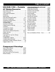
TABLE OF CONTENTS MQ GAW-135H — Portable AC Welder/Generator Here's How To Get Help ............................................ 3 Table Of Contents ..................................................... 4 Parts Ordering Procedures ....................................... 5 Dimensions ............................................................... 6 Specifications ............................................................ 7 Safety Alert Message Symbols .............................
PARTS ORDERING PROCEDURES When ordering parts, please supply the following information: ❒ ❒ ❒ ❒ ❒ ❒ ❒ Dealer account number Dealer name and address Shipping address (if different than billing address) Return fax number Applicable model number Quantity, part number and description of each part Specify preferred method of shipment: ✓ FedEx or UPS Ground ✓ FedEx or UPS Second Day or Third Day Note: Unless otherwise indicated by customer, all orders are treated as “Standard Orders”, and will ✓ FedEx or UPS Nex
GAW-135H — DIMENSIONS Figure 1. Dimensions PAGE 6 — GAW-135H DC WELDER/AC GENERATOR — OPERATION MANUAL — REV.
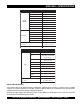
GAW-135H — SPECIFICATIONS Table 1. Specifications (Generator/Welder) Model Rated Output DC ARC WELDER GAW-135H 3.28 kW Max. Current 135 Amps Rated Current 130 Amps Rated Voltage 25.2 VAC Duty Cycle Rated Speed Current Range (Selectable) Applicable Electrode Size 40% 3600 RPM 40, 60, 80, 115 and 135 Amps 3/32" ~ 5/32" Rated Output 1.5 kVA Rated Voltage 120 VAC Rated Current 12.5 Amps AC Generator Phase Frequency Single-phase 60 Hz Power Factor Dimensions (L x W x H) 1 21.9 x 17.7 X 18.
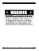
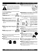
GAW-135H — SAFETY MESSAGE ALERT SYMBOLS FOR YOUR SAFETY AND THE SAFETY OF OTHERS! Safety precautions should be followed at all times when operating this equipment. Failure to read and understand the Safety Messages and Operating Instructions could result in injury to yourself and others. This Owner's Manual has been developed to provide instructions for the safe and efficient operation of the Multiquip Model GAW-135H Portable Generator/Welder.
GAW-135H — SAFETY MESSAGE ALERT SYMBOLS Accidental Starting Respiratory Hazard ALWAYS place the engine ON/OFF switch in the OFF position when the generator is not in use. ALWAYS wear approved respiratory protection. Equipment Damage Messages Sight and Hearing hazard ALWAYS wear approved eye and hearing protection. Other important messages are provided throughout this manual to help prevent damage to your generator, other property, or the surrounding environment.
GAW-135H — RULES FOR SAFE OPERATION DANGER: Failure to follow instructions in this manual may lead to serious injury or even death! This equipment is to be operated by trained and qualified personnel only! This equipment is for industrial use only. The following safety guidelines should always be used when operating the generator/welder GENERAL SAFETY ■ DO NOT operate or service this equipment before reading this entire manual. ■ This equipment should not be operated by persons under 18 years of age.
GAW-135H — RULES FOR SAFE OPERATION ■ NEVER run engine without air cleaner. Severe engine damage may occur. ■ ALWAYS read, understand, and follow procedures in Operator’s Manual before attempting to operate equipment. ■ ALWAYS be sure the operator is familiar with proper safety precautions and operation techniques before using generator. ■ NEVER leave the generator unattended, turn off engine when unattended. ■ Unauthorized equipment modifications will void all warranties.
GAW-135H — RULES FOR SAFE OPERATION DANGER Never use damaged or worn cables when connecting equipment to the generator. Make sure power connecting cables are securely connected to the generator’s output receptacles, incorrect connections may cause damage to the generator and electrical shock.
NOTE PAGE GAW-135H DC WELDER/AC GENERATOR — OPERATION MANUAL — REV.
GAW-135H — OPERATION AND SAFETY DECALS Machine Safety Decals The MQ GAW-135H portable generator/welder is equipped with a number of safety decals (see below and on preceeding page). These decals are provided for operator safety and maintenance information. The illustration below shows these decals as they appear on the machine. Should any of these decals become unreadable, replacements can be obtained from your dealer. PAGE 14 — GAW-135H DC WELDER/AC GENERATOR — OPERATION MANUAL — REV.
GAW-135H — OPERATION AND SAFETY DECALS GAW-135H DC WELDER/AC GENERATOR — OPERATION MANUAL — REV.
GAW-135H — GENERAL INFORMATION GAW-135H Familarization General Inspection Prior to Operation This generator/welder has been thoroughly inspected and accepted prior to shipment from the factory. However, be sure to check for damaged parts or components, or loose nuts and bolts, which could have become disloged in transit.
GAW-135H — LOAD APPLICATION Single Phase Load Always be sure to check the nameplate on the generator and equipment to insure the wattage, amperage and frequency requirements are satisfactorily supplied by the generator for operating the equipment. Generally, the wattage listed on the nameplate of the equipment is its rated output. Equipment may require 130— 150% more wattage than the rating on the nameplate, as the wattage is influenced by the efficiency, power factor and starting system of the equipment.
GAW-135H — CONTROLS AND INDICATORS Figure 2. Generator Controls and Components PAGE 18 — GAW-135H DC WELDER/AC GENERATOR — OPERATION MANUAL — REV.
GAW-135H — CONTROLS AND INDICATORS 1. Engine ON/OFF Switch – Place this switch in the "ON" position to start the engine. To turn-off the engine place this switch in the "OFF" position. 11. Fuel Cock Lever – Turn this lever downward to start (down)the flow of fuel to the carburetor. Turn upward to stop (up) the flow of fuel. 2. Current Selector Knob – Place this knob in the desired setting when welding is required. There are 6 selectable settings that range from 40 amps to 135 amps. 3.
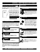
GAW-135H — WELDER/GENERATOR REFUELING DANGER Adding fuel to the tank should be done only when the engine is stopped and has had an opportunity to cool down. In the event of a fuel spill, DO NOT attempt to start the engine until the fuel residue has been completely wiped up, and the area surrounding the engine is dry. If generator is placed in a truck bed with a plastic liner, REMOVE generator from truck bed and place on ground (Figure 3) to refuel.
GAW-135H — INSTALLATION Outdoor Installation Install the generator/welder in a area that is free of debris, bystanders, and overhead obstructions. Make sure the generator is on secure level ground so that it cannot slide or shift around. Also install the generator in a manner so that the exhaust will not be discharged in the direction of nearby homes. Indoor Installation The installation site must be relatively free from moisture and dust.
GAW-135H — INSTALLATION Connecting the Ground The nut and ground terminal on the generator should always be used to connect the generator to a suitable ground. The ground cable should be #8 size wire minimum. At the generator, connect the terminal of the ground cable between the lock washer and the nut (Figure 4) and tighten the nut fully. Connect the other end of the ground cable to a suitable earth ground (ground rod). Figure 4.
GAW-135H — PRE-INSPECTION (ENGINE) CAUTION NEVER operate the generator in a confined area or enclosed area structure that does not provide ample free flow of air. Figure 6. Engine Oil Dipstick (Oil Level) ALWAYS wear approved eye and hearing protection before operating the generator. Before Starting 1. Read safety instructions at the beginning of manual. 2. Clean the generator, removing dirt and dust, particularly the engine cooling air inlet, carburetor and air cleaner. 3.
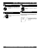
GAW-135H — INITIAL START-UP (ENGINE) CAUTION 2. Place the choke lever (Figure 10) in the "CLOSED " position if starting a cold engine. DO NOT attempt to operate this generator until the Safety, General Information and Inspection sections of this manual have been read and thoroughly understood. This section is intended to assist the operator with the initial start-up of the trash generator. It is extremely important that this section be read carefully before attempting to use the generator in the field.
GAW-135H — INITIAL START-UP/GENERATOR OPERATION 6. If the engine has started, slowly return the choke lever (Figure 13 ) to the “OPEN” position. If the engine has not started repeat steps 1 through 6. 9. Place the main circuit breaker (Figure 15) in the ON position. 7. Before the generator is placed into operation, run the engine for 3-5 minutes. Check for abnormal smells, fuel leaks, and noises that would associate with lose components. 8.
GAW-135H — INITIAL START-UP/GENERATOR OPERATION Stopping The Engine Normal Shutdown 1. Place the main circuit breaker (Figure 11) in the OFF position. 2. Remove the load from the generator, and let the engine run at idle for 3-5 minutes with the idle control switch in the ON position (Up) 3. Place the engine ON/OFF (Figure 24) in the OFF position. Figure 24. Operation Switch (Stop) 4. Place the engine fuel valve lever (Figure 25) to the "OFF" position.” Figure 25.
GAW-135H — WELDER OPERATION Connecting the Welding Cables 1. Make sure the generator/welder is OFF (not running). 2. Attach the correct size terminal connector to the free end of each cable. NEVER connect bare or exposed wires (Figure 23) directly to the terminals. Exposed wiring may cause electrical arcing or dilectric breakdown from poor connection. 3. When connecting the cables NEVER allow the cable or welder output terminals to touch each other. 4.
GAW-135H — WELDER OPERATION Duty Cycle Because of the different types of job applications for which this equipment is intended, the welding-generator is not designed to withstand continuous welding. To avoid overloads, select an appropriate duty cycle. See Table 7. Regulate the welding current with the current selector knob. Never regulate the current by increasing or decreasing the engine operating speed. The operating range of the welding current is listed in Table 8.
GAW-135H — MAINTENANCE General Inspection At least daily or prior to each use, the generating set should be cleaned and inspected for deficiencies. Check for loose, missing or damaged nuts, bolts or other fasteners. Also check for fuel or oil leaks. Service Daily Engine Side (Refer to the Robin Engine Instruction Manual) Cleaning the Fuel Strainer Check Oil Level Clean the fuel strainer if it contains dust or water. Remove dust or water in the strainer cap and wash it in gasoline.
GAW-135H — PREPARATION FOR LONG -TERM STORAGE Generator Storage For storage of the generating set for over 30 days, the following is required: z Drain the fuel tank completely. z Run the engine until the gasoline in the carburetor is completely consumed. z Completely drain the oil from the crankcase and refill with fresh oil. z Remove the spark plug, pour 2 or 3 cc of SAE 30 oil into the cylinder and crank slowly to distribute the oil.
GAW-135H — WIRING DIAGRAM GAW-135H DC WELDER/AC GENERATOR — OPERATION MANUAL — REV.
GAW-135H — TROUBLESHOOTING (ENGINE) Practically all breakdowns can be prevented by proper handling and maintenance inspections, but in the event of a breakdown, please take a remedial action following the diagnosis based on the Engine Troubleshooting (Table 10) information shown below and on the proceeding page. If the problem cannot be remedied, please leave the unit just as it is and consult our company's business office or service plant. TABLE 10.
GAW-135H — TROUBLESHOOTING (ENGINE) TABLE 10. ENGINE TROUBLESHOOTING (CONTINUED) SYMPTOM Insufficient power output "compression" and overheats Burns to much fuel Exhaust color is continiously "WHITE" Exhaust color is continiously "BLACK" POSSIBLE PROBLEM SOLUTION Malfunction in blower? Check or replace blower. Air in-take filter clogged? Clean or replace air in-take filter. Over accumulation of exhaust products? Clean and check valves. Check muffler, replace if necessary.
GAW-135H — TROUBLESHOOTING (GENERATOR) Practically all generator breakdowns can be prevented by proper handling and maintenance inspections, but in the event of a breakdown, please take a remedial action following the diagnosis based on the Generator Troubleshooting (Table 11) information shown below and on the preceding page. If the problem cannot be remedied, please leave the unit just as it is and consult our company's business office or service plant. TABLE 11.
GAW-135H — TROUBLESHOOTING (GENERATOR) TABLE 11. GENERATOR TROUBLESHOOTING (CONTINUED) SYMPTOM Does not decelerate no "VOLTAGE OUTPUT". Does not decelerate but has "VOLTAGE OUTPUT". POSSIBLE PROBLEM SOLUTION Defective rotor windings? Check or replace rotor. Defective solenoid? Check or replace solenoid. Defective idle control device? Check or replace idle control device. Defective solenoid? Check or replace idle control device.
GAW-135H — EXPLANATION OF CODE IN REMARKS COLUMN How to read the marks and remarks used in this parts book. Items Found In the “Remarks” Column NOTE Serial Numbers-Where indicated, this indicates a serial number range (inclusive) where a particular part is used. If more than one of the same reference number is listed, the last one listed indicates newest (or latest) part available.
GAW-135H — SUGGESTED SPARE PARTS MQ GAW-135H WELDER/GENERATOR WITH HONDA GX200VEN2 GASOLINE ENGINE 1 to 3 Units Qty. ... P/N ...................... Description 1 ....... 9924800014 ......... CAP, FUEL TANK 1 ....... 9924800004 ......... FILTER, FUEL TANK 3 ....... 17211ZB2000 ...... ELEMENT, AIR CLEANER 3 ....... 9807956846 ......... SPARK PLUG 1 ....... 28462ZH8003 ...... ROPE, RECOIL STARTER GAW-135H DC WELDER/AC GENERATOR — OPERATION MANUAL — REV.
GAW-135H— NAMEPLATE AND DECALS NAMEPLATE AND DECALS PAGE 38 — GAW-135H DC WELDER/AC GENERATOR — OPERATION MANUAL — REV.
GAW-135H— NAMEPLATE AND DECALS NAMEPLATE AND DECALS NO. PART NO. PART NAME QTY. REMARKS 1 0561200004 DECAL; MQ MULTIQUIP 135A GAW-135H 1 2 9504200004 DECAL; CAUTION NEVER ATTEMPT ................. 1.............REPLACES D90420000 3 0521100003 DECAL; CONTROL PANEL 1 4 8700611904 DECAL; ELECTRICAL SHOCK HAZARD ............. 1.............S-4985 5 0800690804 DECAL; WELDING OUTPUT TERMINAL ............. 1.............S-1238A 6 0820610404 DECAL; WARNING, TRANSFER SWITCH ........... 1.............
GAW-135H— GENERATOR ASSY. GENERATOR ASSY. PAGE 40 — GAW-135H DC WELDER/AC GENERATOR — OPERATION MANUAL — REV.
GAW-135H— GENERATOR ASSY. GENERATOR ASSY. NO. PART NO. 1 0924200004 1A 0101000003 2 0110000913 2 0135000002 3 0155100003 4 0012808020 5 0012308045 6 0012108070 7 0040008000 8 0801086004 9 1153300114 10 1153400212 11 0416700033 12 7935416004 13 0016908045 14 7935419204 15 0207208000 PART NAME ENGINE, HONDA GX200VEN2 GENERATOR ASSY. ROTAR ASSY. ARAMATURE ASSY.
GAW-135H— CONTROL BOX CONTROL BOX ASSY. PAGE 42 — GAW-135H DC WELDER/AC GENERATOR — OPERATION MANUAL — REV.
GAW-135H— CONTROL BOX CONTROL BOX ASSY. NO. PART NO.
GAW-135H— PIPE FRAME AND FUEL TANK ASSY. PIPE FRAME AND FUEL TANK ASSY. PAGE 44 — GAW-135H DC WELDER/AC GENERATOR — OPERATION MANUAL — REV.
GAW-135H— PIPE FRAME AND FUEL TANK ASSY. PIPE FRAME AND FUEL TANK ASSY. NO. PART NO. PART NAME 1 0417000002 PIPE FRAME 2 0416400114 GENERATOR GUARD 3 0016906016 HEX HEAD BOLT 4 0454100003 SIDE GUARD 5 0016906016 HEX HEAD BOLT 6 0019206016 HEX HEAD BOLT 7 0040506000 TOOTHED WASHER 8 0363000022 FUEL TANK 9 0416400204 OVERFLOW GUARD 10 0016998020 HEX HEAD BOLT 11 0602125031 FUEL GUAGE 12 9924800014 CAP, FUEL TANK 13 9924800004 FILTER 14 16950898633 FUEL COCK QTY.
GAW-135H— MUFFLER ASSY. MUFFLER ASSY. PAGE 46 — GAW-135H DC WELDER/AC GENERATOR — OPERATION MANUAL — REV.
GAW-135H— MUFFLER ASSY. MUFFLER ASSY. NO. PART NO.
GX-200VEN2 — CYLINDER HEAD ASSY. CYLINDER HEAD ASSY. PAGE 48 — GAW-135H DC WELDER/AC GENERATOR — OPERATION MANUAL — REV.
GX-200VEN2 —CYLINDER HEAD ASSY. CYLINDER HEAD ASSY. NO. PART NO. 12204ZE1306 1 * 2 122052ZE1315 * 12210ZL00100 3 4 12216ZE5300 * 12251ZL0003 5 6 12310ZE1020 7 12391ZE1000 8 15721883030 9 90013883000 10 90043ZB2003 11 90047ZE1000 12 9430110160 14 957230806000 15 9807956846 15 9807956855 PART NAME QTY. REMARKS GUIDE, IN VALVE O.S. 1 GUIDE, EX. VALVE O.S. 1 HEAD COMP. CYLINDER ................. 1 ................INCLUDES ITEMS W/ * CLIP, VALVE GUIDE 1 GASKET 1 COVER COMP.
GX-200VEN2 — CYLINDER BARREL ASSY. CYLINDER BARREL ASSY. PAGE 50 — GAW-135H DC WELDER/AC GENERATOR — OPERATION MANUAL — REV.
GX-200VEN2 — CYLINDER BARREL ASSY. CYLINDER BARREL ASSY. NO. PART NO. 1 12000ZL0811 2 15510ZE1033 3 16506ZL0000 4 16531ZE1000 5 16541ZE1000 6 90131ZE1000 7 90451ZE1000 8 90601ZE1000 9 90602ZE1000 10 91001ZF1003 * 10 * 91001ZF1004 91202883005 11 * 12 91353671004 13 9405010000 14 9410106800 15 9425108000 16 957010601200 PART NAME QTY. REMARKS CYLINDER BARREL ASSY. .......................... 1 ............ INCLUDES ITEMS W/ * OIL LEVEL SWITCH ASSY. 1 GOVERNOR ASSY.
GX-200VEN2 — CRANKCASE COVER ASSY. CRANKCASE COVER ASSY. PAGE 52 — GAW-135H DC WELDER/AC GENERATOR — OPERATION MANUAL — REV.
GX-200VEN2 — CRANKCASE COVER ASSY. CRANKCASE COVER ASSY. NO. PART NO. PART NAME QTY. REMARKS 2 11300ZE1633 COVER ASSY., CRANKCASE ...................... 1 ............ INCLUDES ITEMS W/ * 4 11381ZL0000 PACKING, CASE COVER 1 5 15600ZE1003 CAP ASSY., OIL FILLER .............................. 1 ............ INCLUDES ITEMS W/# 6 15600ZG4003 CAP ASSY., OIL FILLER .............................. 1 ............
GX-200VEN2 — CRANKSHAFT ASSY. CRANKSHAFT ASSY. PAGE 54 — GAW-135H DC WELDER/AC GENERATOR — OPERATION MANUAL — REV.
GX-200VEN2 — CRANKSHAFT ASSY. CRANKSHAFT ASSY. NO. PART NO. 13 13310ZL0A00 PART NAME CRANKSHAFT COMP. QTY. 1 REMARKS GAW-135H DC WELDER/AC GENERATOR — OPERATION MANUAL — REV.
GX-200VEN2 — PISTON ASSY. PISTON ASSY. PAGE 56 — GAW-135H DC WELDER/AC GENERATOR — OPERATION MANUAL — REV.
GX-200VEN2 — PISTON ASSY. PISTON ASSY. NO. PART NO. 2 11300ZE1633 1 13010ZL0003 1 13011ZL0003 1 13012ZL0003 1 13013ZL0003 2 13101ZL0010 2 13102ZL0010 2 13103ZL0010 2 13104ZL0010 3 13111ZE1000 4 13200ZE1010 5 90001ZE1000 * 6 90551ZE1000 PART NAME QTY. REMARKS COVER ASSY., CRANKCASE 1 RING SET, PISTON STD TEKOKU 1 RING SET, PISTON 0.25 TEKOKU 1 RING SET, PISTON 0.50 TEKOKU 1 RING SET, PISTON 0.75 TEKOKU 1 PISTON, STD 1 PISTON, 0.25 1 PISTON 0.50 1 PISTON 0.75 1 PIN, PISTON 1 ROD ASSY., CONNECTING ROD .......
GX-200VEN2 — CAMSHAFT ASSY. CAMSHAFT ASSY. PAGE 58 — GAW-135H DC WELDER/AC GENERATOR — OPERATION MANUAL — REV.
GX-200VEN2 — CAMSHAFT ASSY. CAMSHAFT ASSY. NO. PART NO. 1 12209ZH8003 2 14100ZL0000 4 14410ZE1000 6 14431ZE1000 7 14451ZE1013 14568ZE1000 8 * 14711ZF1000 9 10 14721ZF1000 11 14731ZL0000 12 14751ZF1000 13 14771ZE1000 14 14773ZE1000 15 14781ZE1000 16 14791ZE1010 17 90012ZE0010 18 90206ZE1000 PART NAME QTY. REMARKS SEAL, VALVE STEM 1 CAMSHAFT ASSY. ....................................... 1 ............
GX-200VEN2 — RECOIL STARTER ASSY. RECOIL STARTER ASSY. PAGE 60 — GAW-135H DC WELDER/AC GENERATOR — OPERATION MANUAL — REV.
GX-200VEN2 — RECOIL STARTER ASSY. RECOIL STARTER ASSY. NO. PART NO. 1 28400ZH8013ZB 2 28405ZL0000ZA 3 28410ZH8003ZB 4 28420ZH8013 5 28422ZH8013 6 28433ZH8003 7 28441ZH8003 8 28442ZH8003 9 28443ZH8003 10 28461ZH8003 11 28462ZH8003 12 9003ZH8003 13 957010601800 PART NAME QTY. REMARKS STARTER ASSY., RECOIL NH1 BLACK .........1 ................ INCLUDES ITEMS W/ * * * SPACER, MOUNTING NH1 BLACK 1 * * CASE COMP.
GX-200VEN2 — FAN COVER ASSY. FAN COVER ASSY. PAGE 62 — GAW-135H DC WELDER/AC GENERATOR — OPERATION MANUAL — REV.
GX-200VEN2 — FAN COVER ASSY. FAN COVER ASSY. NO. PART NO. 1 16584883300 * 19610ZL0000ZD 2 3 19611ZH8820 5 19620ZL0V30 6 196740ZL0V30 8 36100ZH7003 9 36101ZE1010 10 90013883000 11 90022888010 13 906901ZH7D02 14 93500050350A * 957010600800 15 19 34150ZH7003 21 957010600800 PART NAME QTY. REMARKS SPRING, CONTROL ADJUSTING 1 COVER COMP., FAN NH1 BLACK 1 * * PLATE COMP., SIDE ALERT & LAMP 1 SHROUD ASSY., UPPER ............................. 1 ............ INCLUDES ITEMS W/ * SHROUD COMP., LOWER 1 SWITCH ASSY.
GX-200VEN2 — CARBURETOR ASSY. CARBURETOR ASSY. PAGE 64 — GAW-135H DC WELDER/AC GENERATOR — OPERATION MANUAL — REV.
GX-200VEN2 — CARBURETOR ASSY. CARBURETOR ASSY. NO. PART NO. 1 #%+ 16010ZB1015 * 16011ZE0005 2 * 3 16013ZE0005 4 16015ZE0831 6 % 16024ZE1811 * 16028ZE0005 7 * 8 16044ZE0005 * 9 16100ZL0V31 10 16124ZE0005 * 16166ZL0000 11 * 12 16211ZL0000 13 16212ZH8800 14 16221ZH8801 15 16269ZE1800 16 16610ZB2000 17> 9430520122 99101ZH80720 18 * 18 99101ZH80750 * 99101ZH80780 18 * 19 99204ZE20400 * 20 16016ZH7W01 * PART NAME QTY. REMARKS GASKET SET 1 VALVE SET FLOAT 1 FLOAT SET 1 CHAMBER SERT FLOAT ........................
GX-200VEN2 — AIR CLEANER ASSY. AIR CLEANER ASSY. PAGE 66 — GAW-135H DC WELDER/AC GENERATOR — OPERATION MANUAL — REV.
GX-200VEN2 — AIR CLEANER ASSY. AIR CLEANER ASSY. NO. PART NO. 1 17211ZB2000 2 17212ZB2000 3 17220ZB2000 4 17222ZL0V30 5 17231ZB2000 6 17252ZB2000 7 90115459770 8 9405006080 9 957010601000 PART NAME ELEMENT SEPARATOR CASE COMP. STAY COVER SEAL BOLT, WINKER SETTING NUT, FLANGE 6MM BOLT, FLANGE 6X10 QTY. 1 1 1 1 1 1 4 2 1 REMARKS GAW-135H DC WELDER/AC GENERATOR — OPERATION MANUAL — REV.
GX-200VEN2 — MUFFLER ASSY. MUFFLER ASSY. PAGE 68 — GAW-135H DC WELDER/AC GENERATOR — OPERATION MANUAL — REV.
GX-200VEN2 — MUFFLER ASSY. MUFFLER ASSY. NO. PART NO. 1 18310ZB3C00 3 18355898630 4 18381ZE1800 5 92101080200A 6 94001080000S 7 18310ZB2000 8 18325ZH8T90 9 18329ZB2000 10 18381ZH8800 PART NAME QTY. MUFFLER COMP. 1 ARRESTER, SPARK 1 GASKET 1 BOLT, HEX. 8X20 2 NUT, HEX 8MM 2 PROTECTOR, MUFFLER OUTER 1 PROTECTOR, MUFFLER INNER DENYO 1 SEAL, MUFFLER PROTECTOR 2 GASKET 1 REMARKS GAW-135H DC WELDER/AC GENERATOR — OPERATION MANUAL — REV.
GX-200VEN2 — FUEL COCK ASSY. FUEL COCK ASSY. PAGE 70 — GAW-135H DC WELDER/AC GENERATOR — OPERATION MANUAL — REV.
GX-200VEN2 — FUEL COCK ASSY. FUEL COCK ASSY. NO. PART NO. 1 16080898631 2 16081471831 4 16950898632 5 16952883005 17 90854ZB3000 21 950014514040 22 9500202080 PART NAME QTY. REMARKS PACKING SET, COCK 1 CUP, FUEL STRAINER 1 FUEL COCK ASSY. 1 SCREEN SET 1 RUBBER, 9X15X20 1 TUBE, 4.5 140 ............................................... 1 ............ REPLACES 950014500160M CLIP B8, TUBE 2 GAW-135H DC WELDER/AC GENERATOR — OPERATION MANUAL — REV.
GX-200VEN2 — FLYWHEEL ASSY. FLYWHEEL ASSY. PAGE 72 — GAW-135H DC WELDER/AC GENERATOR — OPERATION MANUAL — REV.
GX-200VEN2 — FLYWHEEL ASSY. FLYWHEEL ASSY. NO. PART NO. 1 13331357000 2 19511ZE1000 4 28451ZL0000 5 31110ZL0811 7 90201878003 PART NAME KEY, SPECIAL WOODRUFF, 25 X18 FAN, COOLING PULLEY, STARTER FLYWHEEL COMPLETE, (LAMP) NUT, SPECIAL 14 MM QTY. 1 1 1 1 1 REMARKS GAW-135H DC WELDER/AC GENERATOR — OPERATION MANUAL — REV.
GX-200VEN2 — IGNITION COIL ASSY. IGNITION COIL ASSY. PAGE 74 — GAW-135H DC WELDER/AC GENERATOR — OPERATION MANUAL — REV.
GX-200VEN2 — IGNITION COIL ASSY. IGNITION COIL ASSY. NO. PART NO. 1 30500ZE1033 2 30600ZE1013 3 31630ZL0V31 4 31511ZE1000 5 31512ZE1000 7 90015883000 8 90019883000 9 90121952000 PART NAME QTY. REMARKS IGNITION COIL ASSY. 1 TERMINAL ASSY. HIGH TENSION ............... 1 ............ NICHIWA Y-EZ COIL ASSY., CHARGE 1 CLAMAPER, CORD 1 GROMMET, CORD 1 BOLT, FLANGE 6X28 2 BOLT, FLANGE 5X10 1 BOLT, FLANGEN 6X25 2 GAW-135H DC WELDER/AC GENERATOR — OPERATION MANUAL — REV.
GX-200VEN2 — CONTROL ASSY. CONTROL ASSY. PAGE 76 — GAW-135H DC WELDER/AC GENERATOR — OPERATION MANUAL — REV.
GX-200VEN2 — CONTROL ASSY. CONTROL ASSY. NO. PART NO. 1 30500ZE1033 2 16550ZL0V30 4 16555ZL0V30 5 16559ZL0V30 6 16561ZL0V30 7 16562ZL0V30 18 90015ZE5010 24 9405006000 PART NAME QTY. IGNITION COIL ASSY. 1 ARM COMP, GOVERNOR 1 ROD, GOVERNOR 1 RETURN SPRING, COVENOR SUB. ARM 1 SPRING, GOVERNOR 1 SPRING, THROTTLE RETURN 1 BOLT, GOVERNORT ARM 1 NUT, FLANGE 6MM 1 REMARKS GAW-135H DC WELDER/AC GENERATOR — OPERATION MANUAL — REV.
GX-200VEN2 — RECTIFER ASSY. RECTIFER ASSY. PAGE 78 — GAW-135H DC WELDER/AC GENERATOR — OPERATION MANUAL — REV.
GX-200VEN2 — RECTIFER ASSY. RECTIFER ASSY. NO. PART NO. 1 1628893000 * 2 16270ZL0V30 3 * 31700KAE871 31750ZL0V31 4 * 5 32110ZL0V30 6 36330ZL0V31 * 7 90683SA0003 93500050080A 8 * 9405006000 9 10# 9430520062 11 * 957010601600 12 957010602500 13 16273ZL0V30 * PART NAME QTY. REMARKS SPRING, CHOKER RETURN 1 AUTO THROTTLE ASSY. .............................. 1 ............ INCLUDES ITEMS W/ * CONDENSER UNIT 1 RECTIFIER ASSY., REGULATOR 1 SUB HARNESS ASSY. 1 SOLENOID ASSY. .......................................
GX-200VEN2 — LABEL ASSY. LABEL ASSY. PAGE 80 — GAW-135H DC WELDER/AC GENERATOR — OPERATION MANUAL — REV.
GX-200VEN2 — LABEL ASSY. LABEL NO. 3 14 15 27 ASSY. PART NO. 87521ZL0000 87528ZB2630 87533ZC0630 87532ZH8810 PART NAME EMBLEM MARK, CHOKE MARK, AIR CLEANER MARK, OIL ALERT QTY. 1 1 1 1 REMARKS GAW-135H DC WELDER/AC GENERATOR — OPERATION MANUAL — REV.
Effective: October 1, 2002 PAYMENT TERMS TERMS AND CONDITIONS OF SALE — PARTS 5. Parts must be in new and resalable condition, in the original Multiquip package (if any), and with Multiquip part numbers clearly marked. 6. The following items are not returnable: Terms of payment for parts are net 10 days. FREIGHT POLICY All parts orders will be shipped collect or prepaid with the charges added to the invoice. All shipments are F.O.B. point of origin.
NOTE PAGE GAW-135H DC WELDER/AC GENERATOR — OPERATION MANUAL — REV.
OPERATION AND PARTS MANUAL HERE'S HOW TO GET HELP PLEASE HAVE THE MODEL AND SERIAL NUMBER ON-HAND WHEN CALLING MULTIQUIP CORPORATE OFFICE 18910 Wilmington Ave. Carson, CA 90746 Email: mq@multiquip.com Internet: www.multiquip.com PARTS DEPARTMENT 800-427-1244 310-537-3700 MAYCO PARTS 800-306-2926 310-537-3700 SERVICE DEPARTMENT 800-478-1244 310-537-3700 TECHNICAL ASSISTANCE 800-478-1244 WARRANTY DEPARTMENT 800-421-1244, EXT. 279 310-537-3700, EXT.