PARTS AND OPERATION MANUAL OPERATION AND PARTS MANUAL MODEL DCA-800SSK PORTABLE GENERATOR (STANDARD) Revision #4 (06/03/10) To find the latest revision of this publication, visit our website at: www.mqpower.com THIS MANUAL MUST ACCOMPANY THE EQUIPMENT AT ALL TIMES.
Diesel engine exhaust and some of PAGE 2 — DCA-800SSK (STD) — OPERATION AND PARTS MANUAL — REV.
DCA-800SSK (STD) — OPERATION AND PARTS MANUAL — REV.
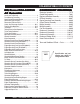
DCA-800SSK TABLE OF CONTENTS MQ Power DCA-600SSK AC Generator Here's How To Get Help .................................................... 3 Parts Ordering Procedures ............................................... 5 Specifications Generator/Engine ...................................... 6 Dimensions (Top and Side) ............................................... 8 Dimensions (Front and Rear) ............................................ 9 Safety Alert Messages Symbols ...............................
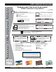
www.mqpower.com PARTS ORDERING PROCEDURES Ordering parts has never been easier! Choose from three easy options: Order via Internet (Dealers Only): Best Deal! Effective: January 1st, 2006 If you have an MQ Account, to obtain a Username and Password, E-mail us at: parts@multiquip. com. Order parts on-line using Multiquip’s SmartEquip website! N View Parts Diagrams N Order Parts N Print Specification Information To obtain an MQ Account, contact your District Sales Manager for more information.
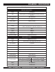
DCA-800SSK — SPECIFICATIONS Table 7. Specifications Generator Specifications Model DCA-800SSK Type Revolving field, self ventilated, open protected type synchronous generator Armature Connection Star with Neutral Phase 3 Standby Output 880KVA (740 KW) Prime Output 800 KVA (640 KW) Voltage 208,220,240,416,440,480 reconnectable (3 phase) 1200,127,139,240,254,277 adjustable (single phase) Frequency 60 Hz Speed 1800 r pm Power Factor 0 .
NOTE PAGE DCA-800SSK (STD) — OPERATION AND PARTS MANUAL — REV.
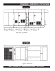
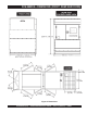
DCA-800SSK — DIMENSIONS (TOP AND SIDE) Figure 1. Dimensions PAGE 8 — DCA-800SSK (STD) — OPERATION AND PARTS MANUAL — REV.
DCA-800SSK— DIMENSIONS (FRONT , REAR AND DOORS) Figure 2. Dimensions DCA-800SSK (STD) — OPERATION AND PARTS MANUAL — REV.
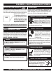
DCA-800SSK — SAFETY MESSAGE ALERT SYMBOLS FOR YOUR SAFETY AND THE SAFETY OF OTHERS! Safety precautions should be followed at all times when operating this equipment. Failure to read and understand the Safety Messages and Operating Instructions could result in injury to yourself and others. This Operation and Parts Manual has been developed to provide complete instructions for the safe and efficient operation of the MQ Power Model DCA-800SSK (60Hz) Whisperwatt™ Generator.
DCA-800SSK — SAFETY MESSAGE ALERT SYMBOLS WARNING - ROTATING PARTS NEVER operate equipment with covers, or guards removed. Keep fingers, hands, hair and clothing away from all moving parts to prevent injury. CAUTION - ACCIDENTAL STARTING ALWAYS place the engine ON/OFF switch in the OFF position when the generator is not in use. CAUTION - OVER-SPEED CONDITIONS NEVER tamper with the factory settings of the engine governor or settings.
DCA-800SSK — RULES FOR SAFE OPERATION DANGER - READ THIS MANUAL! Failure to follow instructions in this manual may lead to serious injury or even DEATH! This equipment is to be operated by trained and qualified personnel only! This equipment is for industrial use only. The following safety guidelines should always be used when operating the DCA-800SSK (60 Hz) Whisperwatt ™ Generator General Safety: ■ DO NOT operate or service this equipment before reading this entire manual.
DCA-800SSK — RULES FOR SAFE OPERATION Generator Grounding To guard against electrical shock and possible damage to the equipment, it is important to provide a good EARTH ground. Article 250 (Grounding) of the National Electrical Code (NEC) provides guide lines for proper grounding and specifies that the cable ground shall be connected to the grounding system of the building as close to the point of cable entry as practical.
DCA-800SSK — RULES FOR SAFE OPERATION Maintenance Safety Battery Safety ■ The electrical voltage required to operate the generator can cause severe injury or even death through physical contact with live circuits. Turn all circuit breakers OFF before performing maintenance on the generator. Use the following guidelines when handling the battery: ■ NEVER lubricate components or attempt service on a running machine.
DCA-800SSK — RULES FOR SAFE OPERATION Towing & Transporting Safety To reduce the possibility of an accident while transporting the generator on public roads, always make sure the trailer that supports the generator and the towing vehicle are in good operating condition and both units are mechanically sound.
DCA-800SSK — INSTALLATION DCA-600SSK — INSTALLATION Figure 3. Typical Generator Grounding Application PAGE 16 — DCA-800SSK (STD) — OPERATION AND PARTS MANUAL — REV.
DCA-800SSK — INSTALLATION Outdoor Installation Generator Grounding Install the generator in a area that is free of debris , bystanders, and overhead obstructions. Make sure the generator is on secure level ground so that it cannot slide or shift around. Also install the generator in a manner so that the exhaust will not be discharged in the direction of nearby homes. To guard against electrical shock and possible damage to the equipment, it is important to provide a good EARTH ground.
DCA-800SSK — TOWING RULES FOR SAFE OPERATION Towing Safety Precautions CAUTION - TOWING REGULATIONS Check with your county or state safety towing regulations before towing your generator. To reduce the possibility of an accident while transporting the generator on public roads, always make sure the trailer (Figure 4) that supports the generator and the towing vehicle are in good operating condition and both units are mechanically sound.
DCA-800SSK — TRAILER-SAFETY GUIDELINES CAUTION - TRAILER INSPECTION ALWAYS make sure the trailer is in good operating condition. Check the tires for proper inflation and wear. Also check the wheel lug nuts for proper tightness. Explanation of Chart: This section is intended to provide the user with trailer service and maintenance information. The service and maintenance guidelines referenced in this section apply a wide range of trailers.
DCA-800SSK — TRAILER-SPECIFICATIONS Table 3. Trailer Specifications MODEL APPLICATION FUEL CELL BRAKE SYSTEM GVWR FRAME LENGTH FRAME WIDTH JACK STAND TRLR-10W SDW225, SGW250,TLW300 NO NO 1,900 LBS. 862 Kg. 96 inches 2.43 meters 50 inches 1.27 meters 800 LBS. (363 Kg.) FULL TILT WHEEL TRLR-10 DCA10, TLG12, DCA15 NO NO 1,900 LBS. 862 Kg. 96 inches 2.43 meters 50 inches 1.27 meters 800 LBS. (363 Kg.
DCA-800SSK — TRAILER-SPECIFICATIONS Table 3. Specifications (Con't) MODEL COUPLER TIRES WHEELS AXLE HUBS SUSPENSION ELECTRICAL TRLR-10W 2" BALL CLASS 2 ADJUSTABLE 175-13C 13"X4.50" 2200# 2X2 5 LUG 3 LEAF 4 WIRE LOOM W/ 4 POLE FLAT TRLR-10 2"BALL CLASS 2 ADJUSTABLE 175-13C 13"X4.5" 2200#2X2 5 LUG 3 LEAF 4 POLE FLAT TRLR-10XF 2"BALL CLASS 2 ADJUSTABLE 175-13C 13"X4.5" 2200#2X2 5 LUG 3 LEAF 4 POLE FLAT 2"BALL CLASS 2 ADJUSTABLE 175-13B 13X4.
DCA-800SSK — OPERATION AND SAFETY DECALS Machine Safety Decals The DCA-800SSK generator is equipped with a number of safety decals. These decals are provided for operator safety and maintenance information. The illustrations below and on the preceding pages shows the decals as they appear on the machine. Should any of these decals become unreadable, replacements can be obtained from your dealer. PAGE 22 — DCA-800SSK (STD) — OPERATION AND PARTS MANUAL — REV.
DCA-800SSK — OPERATION AND SAFETY DECALS DCA-800SSK (STD) — OPERATION AND PARTS MANUAL — REV.
DCA-800SSK — OPERATION AND SAFETY DECALS PAGE 24 — DCA-800SSK (STD) — OPERATION AND PARTS MANUAL — REV.
DCA-800SSK — OPERATION AND SAFETY DECALS DCA-800SSK (STD) — OPERATION AND PARTS MANUAL — REV.
DCA-800SSK — GENERAL INFORMATION DCA-600SSK FAMILIARIZATION Generator The MQ Power Model DCA-800SSK is a 640 kW generator that has been designed as a high quality portable (requires a trailer for transport) power source for telecom sites, lighting facilities, power tools, submersible pumps and other industrial and construction machinery.
DCA-800SSK — MAJOR COMPONENTS DCA-600SSK — MAJOR COMPONENTS Table 4. Generator Major Components ITEM NO. DESCRIPTION 1 Generator Assembly 2 Generator Control Panel Assembly 3 Engine and Radiator Assembly 4 Engine Operating Panel Assembly 5 Battery Assembly 6 Enclosure Assembly 7 Fuel Tank Assembly 8 Muffler Assembly 9 Output Terminal Assembly DCA-800SSK (STD) — OPERATION AND PARTS MANUAL — REV.
DCA-800SSK — GENERATOR CONTROL PANEL Up to S/N 3699247 S/N 3699248~ Figure 6. Generator Control Panel PAGE 28 — DCA-800SSK (STD) — OPERATION AND PARTS MANUAL — REV.
DCA-800SSK — GENERATOR CONTROL PANEL The definitions below describe the controls and functions of the DCA-800SSK " Control Panels " (Figure 9). During cranking cycle , The engine controller will attempt to crank the engine for 10 seconds before disengaging. 1. Circuit Breaker OFF lamp - This indicates the main circuit breaker is "OFF" and the generator is unable to supply power to the load. 2.
DCA-800SSK — ENGINE OPERATING PANEL Up to S/N 3699247 S/N 3699248~ Figure 7. Engine Operating Panels PAGE 30 — DCA-800SSK (STD) — OPERATION AND PARTS MANUAL — REV.
DCA-800SSK — ENGINE OPERATING PANEL The definitions below describe the controls and functions of the DCA-800SSK "Engine Operating Panels " (Figure 11). 1. 2. 3. Air Cleaner Indicators – When lit, indicates air cleaner must be serviced or replaced. This engine of this generator requires two air cleaners. Battery Switch – This switch should be set to the "ON" position during normal operation. When the engine has been stopped, place this switch in the "OFF" position.
DCA-800SSK — OUTPUT TERMINAL OVERVIEW Output Terminal Familiarization The “Output Terminal Panel ” (Figure 8) is provided with the following: Output Terminal Panel Shown below (Figure 8) is the Output Terminal Panel , lift up on the cover to gain access to receptacles and terminal lugs. Three 240/139V output receptacles, 50 amp Three AUX. circuit breakers 240V @50 amps Two 120V GFCI receptacles, 20 amp NOTE Terminal legs "O" and "Ground" are considered bonded grounds.
DCA-800SSK — OUTPUT TERMINAL PANEL OVERVIEW 120 VAC GFCI Receptacles There are two 120 VAC, 20 amp GFCI (Duplex Nema 5-20R) recepacles provided on the output terminal panel. These receptacles can be accessed in any voltage change-over board position. Each receptacle is protected by a 20 amp circuit breaker. These breakers are located directly above the GFCI receptacles. Remember the load output (current) of both GFCI receptacles is dependent on the load requirements of the UVWO terminals.
DCA-800SSK — OUTPUT TERMINAL PANEL OVERVIEW Connecting Loads Loads can be connected to the generator by the UVWO terminal lugs or the convenience receptacles. (See Figure 13). Make sure to read the operation manual before attempting to connect a load to the generator. To protect the UVWO output terminals from overload, a 3pole, 1,600 amp, main circuit breaker is provided. Make sure to switch ALL circuit breakers to the "OFF" position prior to starting the engine.
DCA-800SSK— LOAD APPLICATION Single Phase Load Always be sure to check the nameplate on the generator and equipment to insure the wattage, amperage and frequency requirements are satisfactorily supplied by the generator for operating the equipment. Generally, the wattage listed on the nameplate of the equipment is its rated output. Equipment may require 130— 150% more wattage than the rating on the nameplate, as the wattage is influenced by the efficiency, power factor and starting system of the equipment.
DCA-800SSK — GENERATOR OUTPUTS Generator Output Voltages Generator Amperage A wide range of voltages are available to supply voltage for Tables 8 and 9 describe the generator’s current output capamany different applications. Voltages are selected by apply- bility for both 1Ø-phase and 3Ø phase applications. ing jumpers (6) to the voltage change-over board (Figure 15). To obtain some of the voltages as listed in Table 7 (see Table 8.
DCA-800SSK — GENERATOR OUTPUTS/GAUGE READING Maximum Amps Table 10 shows the maximum amps the generator can provide. DO NOT exceed the maximum amps as listed. Table 9. Maximum Amps Model: DCA600SSK Rated Voltage Maximum Amps Single Phase 120 Volt 1777.8 amps (4 wire) Single Phase 240 Volt 888.9 amps (4 wire) Three Phase 240 Volt 1924.6 amps Three Phase 480 Volt 962.3 amps Figure 17.
DCA-800SSK — OUTPUT TERMINAL PANEL CONNECTIONS UVWO Terminal Output Voltages Various output voltages can be obtained using the UVWO output terminal lugs. The voltages at the terminals are dependent on the placement of the jumpers plates (6) on the Voltage Change-Over Board and the adjustment of the Figure 23. Voltage Regulator Knob Voltage Regulator Control Knob. 1Ø-240V UVWO Terminal Output Voltages Remember the voltage change-over board determines the 1.
DCA-800SSK — OUTPUT TERMINAL PANEL CONNECTIONS 3Ø-480V UVWO Terminal Output Voltages 1. Jumper the voltage change-over board for 480V operation as shown in Figure 26. This configuration uses 6 jumper plates in 3 different positions. Remember there are 2 jumper plates at every position. Every jumper plate must be used. 1Ø-480V UVWO Terminal Output Voltages 1. Make sure the voltage change-over board is jumpered for 480V operation as shown in Figure 26. 2.
DCA-800SSK — PRE-SETUP Fuel Check Circuit Breakers To protect the generator from an overload, a 3-pole, 800 amp, main circuit breaker is provided to protect the UVWO output terminals from overload. In addition two single-pole, 20 amp GFCI circuit breakers are provided to protect the GFCI receptacles from overload. Three 50 amp load circuit breakers have also been provided to protect the auxiliary receptacles from overload.
DCA-800SSK — PRE-SETUP CAUTION - TRAILER FUEL TANK ALWAYS! fill trailer tank first with #2 diesel fuel, before filling secondary internal tank. Figure 32. Skid Type Fuel Tank System Refilling Procedures WARNING - RESPIRATORY HAZARDS Diesel fuel and its vapors are dangerous to your health and the surrounding environment. Avoid skin contact and/or inhaling fumes. 1. Level Tanks – make sure fuel cells are level with the ground.
DCA-800SSK — PRE-SETUP 3. NEVER overfill trailer fuel tank – It is important to read the trailer fuel gauge when filling trailer fuel tank. DO NOT wait for fuel to rise in filler neck. See Figure 35. 5. Figure 35. Full Trailer Tank Figure 37. Full Fuel System 6. CAUTION - REFUELING THE GENERATOR Figure 37 below reflects a full fuel system. Fuel from the engine return line will drain into the secondary internal fuel tank.
DCA-800SSK— PRE-SETUP Coolant (Ethylane Glycol [Green] / Water — 50/50 mix) Use only drinkable tap water. If hard water or water with many impurities is used, the inside of the engine and radiator may become coated with deposits and cooling efficiency will be reduced. An anticorrosion additive added to the water will help prevent deposits and corrosion in the cooling system. See the engine manual for further details.
DCA-800SSK— PRE-SETUP When connecting battery do the following: Battery This unit is of negative ground DO NOT connect in reverse. 1. NEVER connect the battery cables to the battery Always maintain battery fluid level between the specified terminals when the ignition switch is in either the Premarks. Battery life will be shortened, if the fluid level are not Heat, RUN, or START position. ALWAYS make sure properly maintained.
DCA-800SSK — GEN. START-UP PROCEDURE (MANUAL) Before Starting CAUTION - LETHAL EXHAUST HAZARD 1. Place the main, G.F.C.I. and aux. circuit breakers (Figure 42) in the “OFF” position prior to starting the engine. The engine's exhaust contains harmful emissions. ALWAYS have adequate ventilation when operating. Direct exhaust away from nearby personnel. If applicable perform the following: ■ Apply commercial power to the internal battery charger receptacle (to ensure good starting) via commercial power.
DCA-800SSK — GENERATOR START-UP PROCEDURE (MANUAL) 5. Set the battery ON/OFF switch (Figure 45) to the “ON” position. 11. The generator's frequency meter (Figure 50) should be displaying the 60 cycle output frequency in HERTZ. Figure 45. Battery ON/OFF Switch 6. When starting the generator in COLD weather conditions, turn the ignition key to the “PREHEAT ” position (Figure 46), Figure 50. Frequency Meter (Hz) 12. The generator's AC-voltmeter (Figure 51) will display the generator’s output in VOLTS.
DCA-800SSK — GENERATOR START-UP PROCEDURE (MANUAL) 14. The engine oil pressure gauge (Figure 47) will indicate the oil pressure (kg/ cm2) of the engine. Under normal operating conditions the oil pressure is approximately 0 4 kg/cm2 17. Place the main, GFCI, and aux. circuit breakers in the “ON” position (Figure 50). 8 ENGINE OIL PRESSURE Figure 47. Oil Pressure Gauge 15. The coolant temperature gauge (Figure 48) will indicate the coolant temperature.
DCA-800SSK — GENERATOR START-UP PROCEDURE (MANUAL) 22. Place the engine speed switch in the “LOW ” position (Figure 62). BEFORE STARTING Generator and Control Panel WARNING - STARTING THE GENERATOR NEVER! manually start the engine with the main, GFCI or auxiliary circuit breakers in the ON (closed) position. Steps 20 thru 26 are referenced for Engine Operating Panel S/N 3699248~. See Figure 59 below. This panel does not have an ignition switch.
DCA-800SSK — GENERATOR SHUT-DOWN PROCEDURE (AUTO) Starting (Auto Mode) DANGER - ELECTRICAL SYSTEM HAZARDS Before connecting this generator to any building’s electrical system, a licensed electrician must install an isolation (transfer) switch. Serious damage to the building’s electrical system may occur without this transfer switch. CAUTION - ENGINE SPEED SWITCH The Engine Speed Switch must be set to the “High” position when running in the Auto-Start mode.
DCA-600SSK — GENERATOR SHUT-DOWN PROCEDURE Engine Shutdown Ignition Key (Up to S/N 3699247) To shutdown the generator use the following procedure: 1. Place both the MAIN, GFCI and LOAD circuit breakers (Figure 69) to the "OFF position". Engine Shutdown Controller (S/N 3698617~) To shutdown the generator use the following procedure: 1. Place both the MAIN, GFCI and LOAD circuit breakers as shown in Figure 67 to the "OFF position". 2. Place the engine speed switch in the “LOW ” position (Figure 73).
DCA-800SSK — MAINTENANCE Use Table 14 shown below as a general checklist to be performed on a daily basis. TABLE 14.
DCA-800SSK — MAINTENANCE General Inspection Prior to each use, the generating set should be cleaned and inspected for deficiencies. Check for loose, missing or damaged nuts, bolts or other fasteners. Also check for fuel or oil leaks. Air Cleaner Every 50 hours: If dust indicator is RED, clean the air cleaner element. Outer Element: 1. Loosen wing bolt, remove dust cup, then remove wing nut and take out element. 2. Clean the inside of the body and cover using a damp cloth. 3. Blow dry with compressed air (0.
DCA-800SSK — MAINTENANCE WARNING - BURN HAZARDS Allow engine to cool when flushing out radiator. Flushing the radiator while hot could cause serious burns from water or steam. 14. Drain the water inside reserve tank, clean the inside of the reserve tank, then fill with coolant/water mixture to between the full and low lines. 15. Stop the engine, wait for 3 minutes, add tap water until the water level reaches near the water filer port, then tighten the radiator cap.
DCA-800SSK — MAINTENANCE 5. After replacing filter cartridge, loosen air bleed plug. Generator Storage: 6. Loosen the knob of feed pump, and pump it up and down until no bubbles come out with the fuel from air bleed plug. For storage of the generator for over 30 days, the following is required: Fill the fuel tank completely. Treat with fuel stabilizer if 7. After bleeding the air, tighten air bleed plug, then push in necessary. the knob of feed pump and lock it in position.
DCA-800SSK — MAINTENANCE Jacket Water Heater and Internal Battery Charger 120 VAC Input Receptacles (OPTIONAL) This generator is equipped with two 120 VAC, 20 amp input receptacles located on the output terminal panel. The purpose of these receptacles is to provide power via commercial power to the jacket water heater and internal battery charger. These receptacles will ONLY function when commercial power has been supplied to them (Figure 75).
DCA-800SSK — MAINTENANCE Brakes Trailer brakes should be inspected the first 200 miles of operation. This will allow the brake shoes and drums to seat properly. After the first 200 mile interval, inspect the brakes every 3,000 miles. If driving over rough terrain, inspect the brakes more frequently. Air Brake System Air brakes use compressed air to make the brakes function. Air brakes are a good and safe way of stopping large and heavy vehicles.
DCA-800SSK —TRAILER MAINTENANCE Tires/Wheels/Lug Nuts Tires and wheels are a very important and critical components of the trailer. When specifying or replacing the trailer wheels it is important the wheels, tires, and axle are properly matched. CAUTION - EYESIGHT HAZARD ALWAYS wear safety glasses when removing or installing force fitted parts. Failure to comply may result in serious injury. CAUTION - REPAIRING TRAILER WHEELS DO NOT attempt to repair or modify a wheel.
DCA-800SSK —TRAILER MAINTENANCE Table 17. Suspension Torque Requirements Item Torque (Ft.-Lbs.) 3/8" U-BOLT MIN-30 MAX-35 7/16" U-BOLT MIN-45 MAX-60 1/2" U-BOLT MIN-45 MAX-60 SHACKLE BOLT SPRING EYE BOLT SNUG FIT ONLY. PARTS MUST ROTATE FREELY. LOCKING NUTS OR COTTER PINS ARE PROVIDED TO RETAIN NUT-BOLT ASSEMBLY. MIN-30 MAX-50 SHOULDER TYPE SHACKLE BOLT Lug Nut Torque Requirements It is extremely important to apply and maintain proper wheel mounting torque on the trailer.
DCA-800SSK — TRAILER-WIRING DIAGRAM Figure 79. Trailer Wiring Diagram (5-Pin) DCA-800SSK (STD) — OPERATION AND PARTS MANUAL — REV.
DCA-800SSK — TRAILER-WIRING DIAGRAM Figure 80. Trailer Wiring Diagram (7-Pin) PAGE 60 — DCA-800SSK (STD) — OPERATION AND PARTS MANUAL — REV.
DCA-800SSK — GENERATOR WIRING DIAGRAM Figure 81. Generator Wiring Diagram DCA-800SSK (STD) — OPERATION AND PARTS MANUAL — REV.
DCA-800SSK — GENERATOR WIRING DIAGRAM (MAIN BREAKER) Figure 82. Main Circuit Breaker Wiring Diagram PAGE 62 — DCA-800SSK (STD) — OPERATION AND PARTS MANUAL — REV.
DCA-800SSK — ENGINE WIRING DIAGRAM Figure 83. Engine Wiring Diagram DCA-800SSK (STD) — OPERATION AND PARTS MANUAL — REV.
DCA-800SSK — ENGINE WIRING DIAGRAM Figure 84. Engine Wiring Diagram(Continued) PAGE 64 — DCA-800SSK (STD) — OPERATION AND PARTS MANUAL — REV.
DCA-800SSK — ELECTRONIC GOV. CONTROLLER WIRING DIAGRAM Figure 85. Electronic Governor Controller DCA-800SSK (STD) — OPERATION AND PARTS MANUAL — REV.
DCA-600SSK — TROUBLESHOOTING (ENGINE) Practically all breakdowns can be prevented by proper handling and maintenance inspections, but in the event of a breakdown, use Table 20 (Engine Troubleshooting) as a basic guideline for troubleshooting the engine. If the problem cannot be remedied, consult our company's business office or service plant. TABLE 20. ENGINE TROUBLESHOOTING SYMPTOM Engine does not star t. POSSIBLE PROBLEM SOLUTION No fuel? Replenish fuel. Air in the fuel system? Bleed system.
DCA-800SSK — TROUBLESHOOTING (ENGINE) TABLE 20. ENGINE TROUBLESHOOTING (CONTINUED) SYMPTOM Engine revolution is not smooth. Either white or blue exhaust gas is observed. Either black or dark gray exhaust gas is observed. Deficient output. POSSIBLE PROBLEM SOLUTION Fuel filter clogged or dir ty? Clean or change. Air cleaner clogged? Clean or change. Fuel leak due to loose injection pipe retaining nut? Tighten nut. Injection pump malfunctioning? Repair or replace.
DCA-800SSK — TROUBLESHOOTING (GENERATOR/ENGINE) Practically all breakdowns can be prevented by proper handling and maintenance inspections, but in the event of a breakdown, use Table 21 (Generator Troubleshooting) as a basic guideline for troubleshooting the generator. If the problem cannot be remedied, consult our company's business office or service plant. TABLE 21. GENERATOR TROUBLESHOOTING SYMPTOM POSSIBLE PROBLEM SOLUTION AC Voltmeter defective? Check output voltage using a voltmeter.
DCA-800SSK — TROUBLESHOOTING (MPEC) Use Table 22 (Engine Controller Troubleshooting) as a basic guideline for troubleshooting the MPEC. If the problem cannot be remedied, consult our company's business office or service plant. TABLE 22. ENGINE CONTROLLER TROUBLESHOOTING (MPEC) Sympton Low oil pressure light is on. Low coolant level light is on. High coolant temper ture light is on. Possible Cause Solution Low oil level? Fill oil level.
EXPLANATION OF CODE IN REMARKS COLUMN The following section explains the different symbols and remarks used in the Parts section of this manual. Use the help numbers found on the back page of the manual if there are any questions. NOTICE The contents and part numbers listed in the parts section are subject to change without notice. Multiquip does not guarantee the availability of the parts listed. SAMPLE PARTS LIST NO. 1 2% 2% 3 4 PART NO. PART NAME QTY. REMARKS 12345 BOLT......................1 .....
DCA-800SSK — SUGGESTED SPARE PARTS DCA-800SSK W/KOMATSU SA12V140 DIESEL ENGINE 1 TO 3 UNITS 1 to 3 Units Qty. P/N Description 6 ....... 5610262520 ......................AIR FILTER, INNER 12 ..... 5610262530 ......................AIR FILTER, OUTER 12 ..... 6003117111 ......................FUEL FILTER 24 ..... 6002111231 ......................OIL FILTER 6 ....... 6004111171 ......................CARTRIDGE, CORROSION RESISTOR 6 ....... 0810105400 ......................FUEL FILTER, FUEL TANK 1 .......
DCA-800SSK — GENERATOR ASSY. GENERATOR ASSY. PAGE 72 — DCA-800SSK (STD) — OPERATION AND PARTS MANUAL — REV.
DCA-800SSK — GENERATOR ASSY. GENERATOR ASSY.
DCA-800SSK — GENERATOR ASSY. GENERATOR ASSY. PAGE 74 — DCA-800SSK (STD) — OPERATION AND PARTS MANUAL — REV.
DCA-800SSK — GENERATOR ASSY. GENERATOR ASSY. NO PART NO 4 C5153000002 5 C4137000003 6 0012110075 6 0042610000 6 0041210000 7 0845044904 8 0016316045 8 0040016000 8 0041216000 9 C5153300003 10 C5153300104 11 0016308095 11 0040008000 11 0041208000 12 0010110016 13 0803000104 14 8461335004 15 C5131300103 16 0017106012 17 0017106050 18 8461333003 19 0017106012 20 0012112040 20 0042512000 21 C5131300003 22 0017106050 23 0605000012 24 0030020000 24 0040020000 PART NAME END BRACKET FIELD ASSY., EXCITER HEX.
DCA-800SSK — CONTROL PANEL ASSY. CONTROL PANEL ASSY. PAGE 76 — DCA-800SSK (STD) — OPERATION AND PARTS MANUAL — REV.
DCA-800SSK — CONTROL PANEL ASSY. CONTROL PANEL ASSY.
DCA-800SSK — CONTROL BOX ASSY. CONTROL BOX ASSY. PAGE 78 — DCA-800SSK (STD) — OPERATION AND PARTS MANUAL — REV.
DCA-800SSK — CONTROL BOX ASSY. CONTROL BOX ASSY.
DCA-800SSK — CONTROL BOX ASSY. CONTROL BOX ASSY. PAGE 80 — DCA-800SSK (STD) — OPERATION AND PARTS MANUAL — REV.
DCA-800SSK — CONTROL BOX ASSY. CONTROL BOX ASSY.
DCA-800SSK — ENGINE AND RADIATOR ASSY. ENGINE AND RADIATOR ASSY. PAGE 82 — DCA-800SSK (STD) — OPERATION AND PARTS MANUAL — REV.
DCA-800SSK — ENGINE AND RADIATOR ASSY. ENGINE AND RADIATOR ASSY.
DCA-800SSK — ENGINE AND RADIATOR ASSY. ENGINE AND RADIATOR ASSY. PAGE 84 — DCA-800SSK (STD) — OPERATION AND PARTS MANUAL — REV.
DCA-800SSK — ENGINE AND RADIATOR ASSY. ENGINE AND RADIATOR ASSY. NO 37 38 39 40 41 42 43 44 45 46 47 48 49 50 51 52 53 54 54 55 56 57 PART NO 6001813960 6215114410 6151119970 6643114641 6215114470 6215114480 1252151H1 0728900170 C5374200103 C5374200003 0017110030 0017110030 0207010000 0193602800 0605515170 0194201500 0605515019 0728100549 7700751310 0728100549 C5358300204 0412222274 PART NAME QTY. REMARKS CAP, AIR CLEANER ................................ 2 .........
DCA-800SSK — OIL DRAIN ASSY. OIL DRAIN ASSY. PAGE 86 — DCA-800SSK (STD) — OPERATION AND PARTS MANUAL — REV.
DCA-800SSK — OIL DRAIN ASSY. OIL DRAIN ASSY. NO PART NO PART NAME 1 2 2 3 4 5 6 7 8 9 10 11 12 0602023160 0017108040 0207008000 0131710060 0131708060 0130206000 0602022202 3502054124 0802024004 0191602700 0191601600 0605515134 0132006000 PUMP ............................................................. 1 .......... GM-2524H HEX. HEAD BOLT 4 HEX. NUT 4 BUSHING, 1 x 1/2 1 BUSHING 3/4 x 1/2 1 STREET ELBOW, 1/2 3 HOSE JOINT 4 DRAIN JOINT 1 PACKING 1 HOSE 1 HOSE 1 HOSE BAND 4 PLUG, 1/2 1 QTY.
DCA-800SSK — ENGINE OPERATING PANEL ASSY. ENGINE OPERATING PANEL ASSY. PAGE 88 — DCA-800SSK (STD) — OPERATION AND PARTS MANUAL — REV.
DCA-800SSK — ENGINE OPERATING PANEL ASSY. ENGINE OPERATING PANEL ASSY.
DCA-800SSK — OUTPUT TERMINAL ASSY. OUTPUT TERMINAL ASSY. PAGE 90 — DCA-800SSK (STD) — OPERATION AND PARTS MANUAL — REV.
DCA-800SSK — OUTPUT TERMINAL ASSY. OUTPUT TERMINAL ASSY.
DCA-800SSK — OUTPUT TERMINAL ASSY. OUTPUT TERMINAL ASSY. PAGE 92 — DCA-800SSK (STD) — OPERATION AND PARTS MANUAL — REV.
DCA-800SSK — OUTPUT TERMINAL ASSY. OUTPUT TERMINAL ASSY. NO 25 26 27 27 27 28 29 30 30 31 31 32 * 32# 33 34 35 35 35 36 37 PART NO 0030012000 7521865603 0010108030 0030008000 0041208000 C4237100504 0017108020 0601805840 0601808804 C5261600004 G5261600204 0223300150 0221200110 0017106030 0601811034 0027104015 0030004000 0041204000 C4237101203 0601851780 PART NAME QTY. REMARKS HEX. NUT 4 STOPPER 1 HEX. HEAD BOLT 1 HEX. NUT 1 PLAIN WASHER 2 COVER 1 HEX. HEAD BOLT 5 CIRCUIT BREAKER, KM-52 265V 50A ....... 3 .
DCA-800SSK — BATTERY ASSY. BATTERY ASSY. PAGE 94 — DCA-800SSK (STD) — OPERATION AND PARTS MANUAL — REV.
DCA-800SSK — BATTERY ASSY. BATTERY ASSY. NO 1 2 3 4 5 6 7 8 9 10 11 12 13 14 15 16 17 18 PART NO 0168719052 0805018904 0805006404 0805006504 0037808000 0040008000 0041208000 C5347800104 C5347800004 7522280904 C5347600104 C5347400004 0347010030 0208110000 0845040114 0845041004 0602220205 C5347600004 PART NAME BATTERY BATTERY SHEET BATTERY BAND BATTERY BOLT WING NUT LOCK WASHER PLAIN WASHER BATTERY CABLE BATTERY CABLE BATTERY CABLE BATTERY CABLE EARTH CABLE HEX. HEAD BOLT HEX.
DCA-800SSK — MUFFLER ASSY. MUFFLER ASSY. PAGE 96 — DCA-800SSK (STD) — OPERATION AND PARTS MANUAL — REV.
DCA-800SSK — MUFFLER ASSY. MUFFLER ASSY. NO 1 2 2 2 3 4 5 6 6 6 7 7 8 8 8 8 9 9 9 10 11 12 12 12 12 13 14 15 PART NO C5331100002 0019112030 0042312000 0042412000 C5335200104 C5335200204 C5335200304 0019110035 0042310000 0042410000 C5334000103 C4334200504 0010116070 0030016000 0040016000 0041216000 0010116050 0040016000 0041216000 7522355103 C5335200004 0010116070 0030016000 0040016000 0041216000 7525125704 C5331300004 0017108020 PART NAME MUFFLER HEX.
DCA-800SSK — FUEL TANK ASSY. FUEL TANK ASSY. PAGE 98 — DCA-800SSK (STD) — OPERATION AND PARTS MANUAL — REV.
DCA-800SSK — FUEL TANK ASSY. FUEL TANK ASSY.
DCA-800SSK — ENCLOSURE #1 ASSY. ENCLOSURE #1 ASSY. THE PART NUMBER ABOVE INDICATES DEFAULT COLOR OF ORANGE. TO ORDER WITH DIFFERENT COLOR, PLEASE ADD THE FOLLOWING LETTERS WITH THE PART NUMBER: MQGR-GRAY MQGRN-GREEN MQW-WHITE THE SERIAL NUMBER MAY BE REQUIRED. PAGE 100 — DCA-800SSK (STD) — OPERATION AND PARTS MANUAL — REV.
DCA-800SSK — ENCLOSURE #1 ASSY. ENCLOSURE #1 ASSY.
DCA-800SSK — ENCLOSURE #1 ASSY. ENCLOSURE #1 ASSY. THE PART NUMBER ABOVE INDICATES DEFAULT COLOR OF ORANGE. TO ORDER WITH DIFFERENT COLOR, PLEASE ADD THE FOLLOWING LETTERS WITH THE PART NUMBER: MQGR-GRAY MQGRN-GREEN MQW-WHITE THE SERIAL NUMBER MAY BE REQUIRED. PAGE 102 — DCA-800SSK (STD) — OPERATION AND PARTS MANUAL — REV.
DCA-800SSK — ENCLOSURE #1 ASSY. ENCLOSURE #1 ASSY. NO 31 32 33 34 35 35 35 35 36 36 36 36 37 38 39 39 40 40 41 41 42 43 44 45 46 47 48 49 PART NO C5424200103 C5424200203 0019208020 C5434000002 0010120075 0030020000 0040020000 0041220000 0010120065 0030020000 0040020000 0041220000 C5434200003 0207008000 C5464100203 C5464100903 C5464100003 C5464100703 C5464100103 C5464100103 0207008000 0800251701 0019206016 0019208020 0019210025 0600500090 0021106016 C5464500004 PART NAME QTY.
DCA-800SSK — ENCLOSURE #2 ASSY. ENCLOSURE #2 ASSY. THE PART NUMBER ABOVE INDICATES DEFAULT COLOR OF ORANGE. TO ORDER WITH DIFFERENT COLOR, PLEASE ADD THE FOLLOWING LETTERS WITH THE PART NUMBER: MQGR-GRAY MQGRN-GREEN MQW-WHITE THE SERIAL NUMBER MAY BE REQUIRED. PAGE 104 — DCA-800SSK (STD) — OPERATION AND PARTS MANUAL — REV.
DCA-800SSK — ENCLOSURE #2 ASSY. ENCLOSURE #2 ASSY.
DCA-800SSK — ENCLOSURE #2 ASSY. ENCLOSURE #2 ASSY. THE PART NUMBER ABOVE INDICATES DEFAULT COLOR OF ORANGE. TO ORDER WITH DIFFERENT COLOR, PLEASE ADD THE FOLLOWING LETTERS WITH THE PART NUMBER: MQGR-GRAY MQGRN-GREEN MQW-WHITE THE SERIAL NUMBER MAY BE REQUIRED. PAGE 106 — DCA-800SSK (STD) — OPERATION AND PARTS MANUAL — REV.
DCA-800SSK — ENCLOSURE #2 ASSY. ENCLOSURE #2 ASSY.
DCA-800SSK — ENCLOSURE #3 ASSY. ENCLOSURE #3 ASSY. THE PART NUMBER ABOVE INDICATES DEFAULT COLOR OF ORANGE. TO ORDER WITH DIFFERENT COLOR, PLEASE ADD THE FOLLOWING LETTERS WITH THE PART NUMBER: MQGR-GRAY MQGRN-GREEN MQW-WHITE THE SERIAL NUMBER MAY BE REQUIRED. PAGE 108 — DCA-800SSK (STD) — OPERATION AND PARTS MANUAL — REV.
DCA-800SSK — ENCLOSURE #3 ASSY. ENCLOSURE #3 ASSY.
DCA-800SSK — ENCLOSURE #3 ASSY. ENCLOSURE #3 ASSY. THE PART NUMBER ABOVE INDICATES DEFAULT COLOR OF ORANGE. TO ORDER WITH DIFFERENT COLOR, PLEASE ADD THE FOLLOWING LETTERS WITH THE PART NUMBER: MQGR-GRAY MQGRN-GREEN MQW-WHITE THE SERIAL NUMBER MAY BE REQUIRED. PAGE 110 — DCA-800SSK (STD) — OPERATION AND PARTS MANUAL — REV.
DCA-800SSK — ENCLOSURE #3 ASSY. ENCLOSURE #3 ASSY. NO 24 24 25 26 27 28 28 29 29 30 31 32 33 34 34 34 35 36 37 37 37 PART NO 7525176704 7525966704 0019208020 0825007362 0021806016 0845046904 0845045004 0845047004 0845045004 0019208020 0845031504 0601850097 0021008025 0019110070 0042310000 0042410000 B9114000002 0021806016 0019110055 0042310000 0042410000 PART NAME DUCT LINING HEX. HEAD BOLT DOOR HANDLE MACHINE SCREW HINGE WASHER HINGE WASHER HEX. HEAD BOLT CAP STOPPER MACHINE SCREW HEX.
DCA-800SSK — RUBBER SEALS ASSY. RUBBER SEALS ASSY. PAGE 112 — DCA-800SSK (STD) — OPERATION AND PARTS MANUAL — REV.
DCA-800SSK — RUBBER SEALS ASSY. RUBBER SEALS ASSY. NO 1 2 3 4 5 6 7 8 9 10 11 12 13 14 15 16 PART NO 0228901690 0228900995 0228901035 0228901090 0229201950 0228801030 0228801590 0229200710 0229201840 0229200625 0229201840 0228100380 0228100550 0228100120 0228100580 0228901000 PART NAME RUBBER SEAL RUBBER SEAL RUBBER SEAL RUBBER SEAL RUBBER SEAL RUBBER SEAL RUBBER SEAL RUBBER SEAL RUBBER SEAL RUBBER SEAL RUBBER SEAL RUBBER SEAL RUBBER SEAL RUBBER SEAL RUBBER SEAL RUBBER SEAL QTY.
DCA-800SSK — NAME PLATE AND DECALS NAME PLATE AND DECALS PAGE 114 — DCA-800SSK (STD) — OPERATION AND PARTS MANUAL — REV.
DCA-800SSK — NAME PLATE AND DECALS NAME PLATE AND DECALS NO PART NO 1 2 0800520904 0800520904 3 0800520814 4 5 6 7 8 9 10 11 0800564004 0800565004 0800588004 0840624504 0840624604 0840624704 0840624804 B9531100604 12 13 14 15 16 17 C5551000303 C5561100903 Z0110001204 Z0110001304 Z0110001404 Z0110001504 PART NAME QTY. REMARKS CONTROL PANEL GROUP PLATE; ON-OFF ............................................ 1 ....... AT-202 PLATE; AMMETER CHANGE-OVER SWITCH .............................................
DCA-800SSK — NAME PLATE AND DECALS NAME PLATE AND DECALS PAGE 116 — DCA-800SSK (STD) — OPERATION AND PARTS MANUAL — REV.
DCA-800SSK — NAME PLATE AND DECALS NO PART NO PART NAME 29 30 31 32 33 34 0800689204 B9504000304 B9504000404 B9504100104 0966810000 6162937111 ENGINE & RADIATOR GROUP DECAL; COOLING WATER ................................. 1 ........ S-961 DECAL; CAUTION HOT PARTS ......................... 1 ........ B90400030 DECAL; WARNING MOVING PARTS .................. 2 ........ B90400040 DECAL; WARNING HOT COOLANT .................. 1 ........ B90410010 DECAL; WARNING ..............................................
TERMS AND CONDITIONS OF SALE — PARTS PAYMENT TERMS 5. Parts must be in new and resalable condition, in the original Multiquip package (if any), and with Multiquip part numbers clearly marked. 6. The following items are not returnable: Multiquip reserves the right to quote and sell direct to Government agencies, and to Original Equipment Manufacturer accounts who use our products as integral parts of their own products. a. SPECIAL EXPEDITING SERVICE Terms of payment for parts are net 30 days.
NOTE PAGE DCA-800SSK (STD) — OPERATION AND PARTS MANUAL — REV.
OPERATION AND PARTS MANUAL HERE’S HOW TO GET HELP PLEASE HAVE THE MODEL AND SERIAL NUMBER ON-HAND WHEN CALLING MULTIQUIP CORPORATE OFFICE 18910 Wilmington Ave Tel. (800) 421-1244 Carson, CA 90746 Fax (800) 537- 3927 Contact: mq@multiquip.com Web: www.multiquip.com MQ Power 1800 Water Ridge Rd. Tel. (800) 883-2551 Suite 500/600 Fax (972) 315-1847 Lewisville, TX 75057 Contact: mqpower@multiquip.com Web: www.mqpower.