OPERATION AND PARTS MANUAL SERIES MODEL MVC-82VH/VHW ONE-WAY PLATE COMPACTOR (HONDA GX160U1SM12 GASOLINE ENGINE) Revision #1 (04/25/08) To find the latest revision of this publication, visit our website at: www.multiquip.com THIS MANUAL MUST ACCOMPANY THE EQUIPMENT AT ALL TIMES.
PROPOSITION 65 WARNING PAGE 2 — MVC-82VH/VHW PLATE COMPACTOR • OPERATION AND PARTS MANUAL — REV.
NOTES MVC-82VH/VHW • OPERATION AND PARTS MANUAL — REV.
TABLE OF CONTENTS MVC-82VH/VHW PLATE COMPACTOR HONDA GX160U1SM12 ENGINE DRA WINGS DRAWINGS Proposition 65 Warning ........................................... 2 Table of Contents .................................................... 4 Parts Ordering Procedures ..................................... 5 Safety ................................................................... 6-7 Rules and Regulations ....................................... 8-10 Specifications .................................................
www.multiquip.com PARTS ORDERING PROCEDURES Ordering parts has never been easier! Choose from three easy options: Effective: January 1st, 2006 Best Deal! Order via Internet (Dealers Only): If you have an MQ Account, to obtain a Username and Password, E-mail us at: parts@multiquip.com. Order parts on-line using Multiquip’s SmartEquip website! ■ View Parts Diagrams ■ Order Parts ■ Print Specification Information To obtain an MQ Account, contact your District Sales Manager for more information.
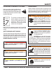
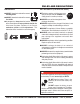
SAFETY FOR YOUR SAFETY AND SAFETY OF OTHERS! HAZARD SYMBOLS Safety precautions should be followed at all times when operating this equipment. Failure to read and understand the Safety Messages and Operating Instructions could result in injury to yourself and others. Potential hazards associated with the operation of this equipment will be referenced with Hazard Symbols which appear throughout this manual, and will be referenced in conjunction with Safety Message Alert Symbols.
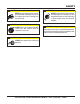
SAFETY CAUTION — Rotating Parts Hazards NEVER operate equipment with covers or guards removed. Keep fingers, hands, hair and clothing away from all moving parts to prevent injury. CAUTION — Overspeed Conditions NEVER tamper with the factory setting of the engine governor. Personal injury and equipment damage can result if operating in speed ranges above the maximum allowable.
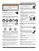
RULES AND REGULATIONS WARNING — Read This Manual Failure to follow instructions in this manual may lead to serious injury or even DEATH! This equipment is to be operated by trained and qualified personnel only! This equipment is for industrial use only. GENERAL SAFETY DO NOT operate or service this equipment before reading this entire manual. This equipment should not be operated by persons under 18 years of age.
RULES AND REGULATIONS LOADING AND UNLOADING REFUELING Before lifting, make sure that equipment parts (hook and vibration insulator) are not damaged and screws are not loosened or lost. FUEL ALWAYS make sure crane or lifting device has been properly secured to the lifting bail (hook) of the equipment. NEVER lift the equipment while the engine is running. Use adequate lifting cable (wire or rope) of sufficient strength. Use one point suspension hook and lift straight upwards.
RULES AND REGULATIONS EMERGENCIES BATTERY SAFETY (FOR ELECTRIC START) ALWAYS know the location of the nearest fire extinguisher. ■ The battery contains acids that can cause injury to the eyes and skin. ALWAYS wear safety glasses to avoid eye irritation. ALWAYS know the location of the nearest first aid kit. In emergencies, always know the location of the nearest phone or keep a phone on the job site. Also know the phone numbers of the nearest ambulance , doctor and fire department .
SPECIFICATIONS Table 1. Specifications (Compactor) Models MVC-82VH/MVC-82VHW Handle HAV (Center Handle) 3080 lbf. (13.7 kN) Centrifugal Force Number of Vibrations 5,600 vibrations/min (93 Hz) Traveling Speed 82 ft./min (25meters/min) Plate Size (LxW) 22.4 x 17.7 in. (570 x 450 mm) Length (Including Handle) 38.2 in. (970 mm) Height (Including Handle) 38.0 in. (965 mm) Height (Without Handle) 22.4 in. (570 mm) Operating Weight (VH) Operating Weight (VHW) 181 lbs. (82 kg.) 198 lbs. (90 kg.
DIMENSIONS C B D E A Table 3. Dimensions Reference Letter Description Dimension A Length (including handle ) 38.2 inches (970 mm) B Height (without handle) 22.4 inches (570 mm) C Height (including handle) 38 inches (965 mm) D Plate Length 22.4 inches (570 mm) E Plate Width 17.7 inches (450 mm) PAGE 12 — MVC-82VH/VHW PLATE COMPACTOR • OPERATION AND PARTS MANUAL — REV.
GENERAL INFORMATION DEFINITION OF PLATE COMPACTOR FREQUENCY/SPEED The Mikasa MVC-82VH/VHW is a walk-behind, one-way plate compactor designed for the compaction of sand, mixed soils and asphalt. This plate compactor is a powerful compacting tool capable of applying a tremendous force in consecutive high frequency vibrations to a soil surface. Its applications include compacting for road, embankments and reservoirs as well as backfilling for gas pipelines, water pipelines and cable installation work.
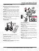
COMPONENTS (COMPACTOR) 1 10 4 9 3 2 WATER TANK (MVC-82VHW ONLY) 5 8 7 6 Figure 1. Plate Compactor Controls and Components Figure 1 shows the location of the basic controls and components of the MVC-80VH/VHW Plate Compactor. The function of each control is described below: 1. Water Tank Cap (VHW Only) – Remove this cap to add water to the water tank. 6. Belt Cover – Remove this cover to gain access to the V-belts. NEVER run the compactor without the V-belt cover.
COMPONENTS (ENGINE) Figure 2. Engine Controls & Components ENGINE COMPONENTS The engine (Figure 2) must be checked for proper lubrication and filled with fuel prior to operation. Refer to the manufacturer's engine manual for instructions and details of operation and servicing. 1. Fuel Filler Cap – Remove this cap to add unleaded gasoline to the fuel tank. Make sure cap is tightened securely. DO NOT over fill.
INSPECTION BEFORE STARTING The Oil Alert System will automatically stop the engine before the engine falls below safe limits. Always be sure to check the engine oil level prior to starting the engine. 1. Read safety instructions at the beginning of manual. 2. Clean the compactor, removing dirt and dust, particularly the engine cooling air inlet, carburetor and air cleaner. 3. Check the air filter for dirt and dust. If air filter is dirty, replace air filter with a new one as required. 4.
INSPECTION V-BELT CHECK CAUTION — V-Belt Check 2. The V-belt tension is proper if the V-belt bends 10 to 15 mm (Figure 7) when depressed with finger midway between the clutch and vibration pulley shafts. NEVER attempt to check the V-belt with the engine running. Severe injury can occur if your hand (Figure 5) gets caught between the V-belt and the clutch. Always use safety gloves. CLUTCH PULLEY Figure 7. V-Belt Tension VIBRATOR PULLEY Figure 5. V-Belt Hazard 1.
OPERATION The CLOSED position of the choke lever enriches the fuel mixture for starting a COLD engine. The OPEN position provides the correct fuel mixture for normal operation after starting, and for restarting a warm engine. CAUTION — Read Manual DO NOT attempt to run the compactor until the Safety and Initial Start-up sections have been read and understood. 4. Place the throttle lever (Figure 12) halfway between fast and slow. INITIAL START-UP 1.
OPERATION 6. If the engine has started, slowly return the choke lever (Figure 11) to the CLOSED position. If the engine has not started, repeat steps 1 through 5. 7. Before the compactor is put into operation, run the engine for 3-5 minutes. 8. Check for abnormal engine noises or fuel leaks. OPERATION CAUTION — Follow Safety Rules Make sure to follow all safety rules referenced in the safety section of this manual before operating compactor.
MAINTENANCE CAUTION — Inspection Inspection and Service CAUTION — Inspection Intervals Inspection and other services should always be carried out on hard and level ground with the engine shutdown. These inspection intervals are for operation under normal conditions. Adjust your inspection intervals based on the number hours plate compactor is in use, and particular working conditions.
MAINTENANCE 3. Replace engine oil with recommended type oil as listed in Table 4. For engine oil capacity, see Table 2 (engine specifications). DO NOT overfill. Table 6.
MAINTENANCE SPARK PLUG Checking Clutch 1. Remove and clean the spark plug (Figure 16). Check the clutch simultaneously with V-belt checking. With belt removed, check outer drum of the clutch for seizure and "V" groove for wear or damage with your eyes. Clean the "V" groove as necessary. Wear of lining or shoe should be checked with running check. If the shoe is worn, power transmission becomes deficient and slipping will result. 2. Adjust the spark gap to 0.028 ~0.031 inch (0.6~0.7 mm).
TROUBLESHOOTING Practically all breakdowns can be prevented by proper handling and maintenance inspections, but in the event of a breakdown, please take remedial action following the diagnosis based on the following troubleshooting tables. If the problem cannot be remedied, please leave the unit as is and consult Multiquip's service department. Table 8.
TROUBLESHOOTING Table 8. Engine Troubleshooting (continued) Symptom "Weak in power" compression is proper and does not misfire. Possible Cause Solution Air cleaner not clean? Clean or replace air cleaner Improper level in carburetor? Check float adjustment, re-build carbureator. Defective Spark plug? Clean or replace spark plug. Defective Spark plug? "Weak in power" compression is proper but misfires. Engine overheats. Rotational speed fluctuates. Recoil star ter malfunction.
NOTES MVC-82VH/VHW • OPERATION AND PARTS MANUAL — REV.
EXPLANATION OF CODE IN REMARKS COLUMN The following section explains the different symbols and remarks used in the Parts section of this manual. Use the help numbers found on the back page of the manual if there are any questions. The contents and part numbers listed in the parts section are subject to change without notice. Multiquip does not guarantee the availibility of the parts listed. * * Numbers Used - Item quantity can be indicated by a number, a blank entry, or A/R.
SUGGESTED SPARE PARTS MVC-80VH/VHWCOMPACTOR WITH HONDA GX160U1SM12 ENGINE 1 TO 5 UNITS Qty. P/N Description 3 ......... 070100312 ............ V-BELT 4 ......... 939010254 ............ SHOCK ABSORBER 3 ......... 9807956846 .......... SPARK PLUG 1 ......... 28462ZH8003 ....... ROPE, RECOIL STARTER 3 ......... 17210ZE1517 ....... ELEMENT, AIR CLEANER 1 ......... 17620Z4H000 ....... CAP, FUEL TANK 1 ......... 17672ZE2W01 ...... FUEL FILTER, FUEL TANK MVC-82VH/VHW • OPERATION AND PARTS MANUAL — REV.
NAMEPLATE AND DECALS 1 ” • 2 5 ˜ – — 3 4 RPF-3310 NPA-759 š 7 6 ™ 8 › Honda GX160U1SM12 / 8 % 8 * * 1 0 & # ) : œ 9 CAUTIO N ! READ OWNERS SERVICE MANUAL BEFORE OPERATING OR SE RVICING THIS MACHINE. ALWAYS KEEP UNAUTHORIZED , INEXPERIENCED, UNTRAINED PEOPLE AWAY FROM THIS MACHINE. MAKE SUR E ALL SAFETY DEVICES ARE OPERATIONAL BEFORE THIS MACHIN E IS S TARTED.
NAMEPLATE AND DECALS NO. 1 2 3 4 5 6 7 8 9 PART NO. 920209890 920212320 920207590 920203060 920201580 920101410 920105070 920203290 PART NAME QTY. REMARKS PLATE, SERIAL NO. .............................. 1 .......... CONTACT MQ PARTS DEPT. DECAL, CAUTION (ICON) ..................... 1 .......... NPA-989 DECAL, FUEL CAUTION ....................... 1 .......... NPA-1232 DECAL, V-BELT (RPF-3310) ................. 1 .......... NPA-759 DECAL, CAUTION ................................. 1 ..........
BODY ASSY.
BODY ASSY. NO. 1 3 4 5 6 7 11 13 14-1 14-2 14-3 16 17 21 23 25 26-1 26-2 26-3 27 28-1 28-2 28-3 29 31 32 33 36 37 38 39 40 41-1 41-2 42 45 46 47-1 47-2 60 61# 62# 63# 64# 65# PART NO.
VIBRATOR ASSY. 69-1 67 68 69-2 62 72 63 61 64 71 78 79 74 72 68 65 69-1 69-2 77-2 66 70 73 75 77-1 PAGE 32 — MVC-82VH/VHW PLATE COMPACTOR • OPERATION AND PARTS MANUAL — REV.
VIBRATOR ASSY. NO. 61 62 63 64 65 66 67 68 69-1 69-2 70 71 72 73 74 75 77-1 77-2 78 79 PART NO. 418117730 001221445 030214350 031114260 418456950 060403020 418456960 418456970 001220820 030208200 418460130 418343630 040406307 418456981 951401920 952403450 001221030 030210250 953400270 953405260 PART NAME VIBRATING CASE BOLT 14X45 T WASHER, LOCK M14 WASHER, FLAT M14 CASE COVER/PULLEY OIL SEAL TC-30458 CASE COVER/SHUT OFF PACKING BOLT 8X20 T WASHER, LOCK M8 COVER SEAL, VIBRATOR ECC.
WATER TANK ASSY. (MVC82VHW ONLY) 103 104 102 101 106 108 111 105 115 107 91 109 116 112 113 110 92 114 92 PAGE 34 — MVC-82VH/VHW PLATE COMPACTOR • OPERATION AND PARTS MANUAL — REV.
WATER TANK ASSY. (MVC82VHW ONLY) NO. 91 92 101 102# 103# 104# 105# 106 107 108 109 110 111 112 113 114 115 116 PART NO. 418118581 002211025 418910080 954300342 001241030 033910010 022910180 954403241 959403790 418458320 418345150 418345160 001740825 033910110 020308064 418459330 416453780 418457890 PART NAME QTY. REMARKS GUARD HOOK 1 BOLT 10X25 H, SW 3 WATER TANK W/CAP (ORANGE) ......... 1 .......... INCLUDES ITEMS W/ # CAP, WATER TANK (NBR) 1 BOLT 10X30 U 1 WASHER 10.
HONDA GX160U1SM12 ENGINE — CYLINDER HEAD ASSY. 5 11 15 9 6 7 11 14 14 14 12 4 2 12 1 14 8 10 10 3 9 9 PAGE 36 — MVC-82VH/VHW PLATE COMPACTOR • OPERATION AND PARTS MANUAL — REV.
HONDA GX160U1SM12 ENGINE — CYLINDER HEAD ASSY. NO. 1% 2% 3 4%# 5 6 7 8 9 10 11 12 14 15 PART NO. 12204ZE1306 12205ZE1315 12210ZH8405 12216ZE5300 12251ZH1800 12310ZE1020 12391ZE1000 15721ZH8000 90013883000 90043ZE1020 90047ZE1000 9430110160 957230806000 9807956846 PART NAME QTY. REMARKS GUIDE, IN. VALVE (OS), OPTIONAL 1 GUIDE, EX. VALVE (OS), OPTIONAL ... 1 .......... INCLUDES ITEMS W/ # HEAD COMP., CYLINDER ..................... 1 ..........
HONDA GX160U1SM12 ENGINE — CYLINDER BARREL ASSY. 15 3 7 17 10 12 19 2 16 19 17 18 1 13 8 11 11 9 13 9 14 PAGE 38 — MVC-82VH/VHW PLATE COMPACTOR • OPERATION AND PARTS MANUAL — REV.
HONDA GX160U1SM12 ENGINE — CYLINDER BARREL ASSY. NO. 1 2 3 7 8 9 10 11 12 13$ 14$ 15 16 17 18 19 PART NO. 12000ZH8426 15510ZE1033 16510ZE1000 16531ZE1000 16541ZE1000 90131ZE1000 90451ZE1000 90601ZE1000 90602ZE1000 91001ZF1003 91201Z0T801 91353671004 9405010000 9410106800 9425108000 957010601200 PART NAME QTY. REMARKS CYLINDER BARREL ASSY. .................. 1 .......... INCLUDES ITEMS W/ $ SWITCH ASSY., OIL LEVEL 1 GOVERNOR ASSY.
HONDA GX160U1SM12 ENGINE — CRANKCASE COVER ASSY. PAGE 40 — MVC-82VH/VHW PLATE COMPACTOR • OPERATION AND PARTS MANUAL — REV.
HONDA GX160U1SM12 ENGINE — CRANKCASE COVER ASSY. NO. 1 3 4 5 9# 10+ 11 * 12 13 14 * PART NO. 11300ZE1642 11381ZH8801 15600ZE1003 15600ZG4003 15625ZE1003 15625ZE1003 91201Z0T801 9430108140 957010803200 961006205000 PART NAME QTY. REMARKS COVER ASSY., CRANKCASE ............... 1 .......... INCLUDES ITEMS W/ * GASKET, CRANKCASE 1 CAP ASSY., OIL FILLER (GRAY) .......... 1 .......... INCLUDES ITEMS W/ # CAP ASSY., OIL FILLER ....................... 1 ..........
HONDA GX160U1SM12 ENGINE — CRANKSHAFT ASSY. PAGE 42 — MVC-82VH/VHW PLATE COMPACTOR • OPERATION AND PARTS MANUAL — REV.
HONDA GX160U1SM12 ENGINE — CRANKSHAFT ASSY. NO. 1 PART NO. PART NAME 13310ZE1000 CRANKSHAFT QTY. 1 REMARKS MVC-82VH/VHW • OPERATION AND PARTS MANUAL — REV.
HONDA GX160U1SM12 ENGINE — PISTON/RINGS ASSY. PAGE 44 — MVC-82VH/VHW PLATE COMPACTOR • OPERATION AND PARTS MANUAL — REV.
HONDA GX160U1SM12 ENGINE — PISTON/RINGS ASSY. NO. 1 1 1 1 2 2 2 2 3 4 5 * 6 PART NO. 13010ZL0003 13011ZL0003 13012ZL0003 13013ZL0003 13101ZH8010 13102ZH8010 13103ZH8010 13104ZH8010 13111ZE1000 13200ZE1010 90001ZE1000 90551ZE1000 PART NAME QTY. REMARKS RING SET, PISTON (STD) 1 RING SET, PISTON (OS 0.25) 1 RING SET, PISTON (OS 0.50) 1 RING SET, PISTON (OS 0.75) 1 PISTON (STD) 1 PISTON (OS 0.25) 1 PISTON (OS 0.50) 1 PISTON (0.75) 1 PIN, PISTON 1 ROD ASSY., CONNECTING .................. 1 ..........
HONDA GX160U1SM12 ENGINE — CAMSHAFT ASSY. PAGE 46 — MVC-82VH/VHW PLATE COMPACTOR • OPERATION AND PARTS MANUAL — REV.
HONDA GX160U1SM12 ENGINE — CAMSHAFT ASSY. NO. 1 2 4 6 7 8 9 * 10 11 12 13 14 15 16 17 18 PART NO. 12209ZH8003 14100ZE1812 14410ZE1010 14431ZE1000 14441ZE1010 14451ZE1013 14568ZE1000 14711ZF1000 14721ZF0000 14751ZF1000 14771ZE1000 14773ZE1000 14781ZE1000 14791ZE1010 90012ZE0010 90206ZE1000 PART NAME QTY. REMARKS SEAL, VALVE STEM 1 CAMSHAFT ASSY. ................................ 1 ..........
HONDA GX160U1SM12 ENGINE — RECOIL STARTER ASSY. 12 7 5 8 14 6 4 10 11 5 1 13 9 2 15 PAGE 48 — MVC-82VH/VHW PLATE COMPACTOR • OPERATION AND PARTS MANUAL — REV.
HONDA GX160U1SM12 ENGINE — RECOIL STARTER ASSY. NO. 1 2 * 4 * 5 * 6 * 7 * 8 * 9 * 10 * 11 * 12 * 13 14 * 15 PART NO. 28400ZH8023ZB 28410ZH8003ZB 28421ZH8801 28422ZH8801 28431ZH8801 28433ZH8801 28441ZH8801 28442ZH8003 28443ZH8001 28461ZH8003 28462ZH8003 90003ZH8801 90008ZE2003 90008ZE2003 PART NAME QTY. REMARKS STARTER ASSY., RECOIL .............. 1 ..........
HONDA GX160U1SM12 ENGINE — FAN COVER ASSY. 6 14 25 2 22 16 21 17 10 20 20 20 PAGE 50 — MVC-82VH/VHW PLATE COMPACTOR • OPERATION AND PARTS MANUAL — REV.
HONDA GX160U1SM12 ENGINE — FAN COVER ASSY. NO. 2 6 10 14 16 17 20 21 22 25 PART NO. 19610ZE1000ZC 19611ZH8810 19630ZH8000 34150ZH7003 36101ZE1010 36100ZF6P81 90013883000 90022888010 90601ZH7013 957010600800 PART NAME QTY. COVER, FAN (BLACK) 1 PLATE, SIDE (OIL ALERT) 1 SHROUD 1 ALERT UNIT, OIL 1 CORD, STOP SWITCH (370MM) 1 SWITCH ASSY., ENGINE STOP 1 BOLT, FLANGE (6 X 12) 6 BOLT, FLANGE (6 X 20) 1 CLIP, HARNESS 1 BOLT, FLANGE (6 X 8) 1 REMARKS MVC-82VH/VHW • OPERATION AND PARTS MANUAL — REV.
HONDA GX160U1SM12 ENGINE — CARBURETOR ASSY. 15 38 14 31 26 2 27 25 17 20 28 11 13 29 6 12 37 3 34 9 16 4 10 2 5 8 2 2 7 PAGE 52 — MVC-82VH/VHW PLATE COMPACTOR • OPERATION AND PARTS MANUAL — REV.
HONDA GX160U1SM12 ENGINE — CARBURETOR ASSY. NO. 2 * 3 * 4 * 5 * 6 * 7 * 8 * 9 * 10 11 * 12 * 13 * 14 15 16 17 20 25 * 26 * 27 * 28 * 29 * 31 * 34# 37 * 38 * PART NO. 16010ZE1812 16011ZE0005 16013ZE0005 16015ZE0831 16016ZH7W01 16024ZE1811 16028ZE0005 16044ZE0005 16100ZH8W51 16124ZE0005 16166ZH8W50 16173001004 16211ZE1000 16212ZH8800 16220ZE1020 16221ZH8801 16610ZE1000 16953ZE1812 16954ZE1812 16956ZE1811 16957ZE1812 16967ZE0811 93500030061H 9430520122 99101ZH80700 99204ZE00350 PART NAME QTY.
HONDA GX160U1SM12 ENGINE — AIR CLEANER ASSY. 10 1 4 12 2 10 5 8 3 9 7 6 7 11 11 PAGE 54 — MVC-82VH/VHW PLATE COMPACTOR • OPERATION AND PARTS MANUAL — REV.
HONDA GX160U1SM12 ENGINE — AIR CLEANER ASSY. NO. 1 2 3 * 4 5 * 6 7# 8# 9 10 11 12 PART NO. 16271ZE1000 17210ZE1517 17218ZE1507 17230ZE1820 17232891000 17235ZE1831 17238ZE7010 17239ZE1000 17410ZE1020 90325044000 9405006000 957010602000 PART NAME QTY. REMARKS GASKET, ELBOW 1 ELEMENT, AIR CLEANER .................... 1 .......... INCLUDES ITEMS W/ * FILTER (OUTER) 1 COVER, AIR CLEANER 1 GROMMET, AIR CLEANER 1 NOISE, MUFFLER 1 COLLAR, AIR CLEANER 2 COLLAR B, AIR CLEANER 1 ELBOW, AIR CLEANER ..................
HONDA GX160U1SM12 ENGINE — MUFFLER ASSY. 19 19 22 2 4 15 7 6 16 19 16 19 5 23 27 9 23 17 23 PAGE 56 — MVC-82VH/VHW PLATE COMPACTOR • OPERATION AND PARTS MANUAL — REV.
HONDA GX160U1SM12 ENGINE — MUFFLER ASSY. NO. 2 4 5 6 7 9 15 16 17 19 22 23 PART NO. 18310ZH8810 18320ZF1H01 18325ZE1010 18340ZE1010 18355ZE1000 18381ZH8800 18522ZE1000 90002ZG0003 94001080000S 90050ZE1000 90055ZE1000 90055ZE1000 PART NAME MUFFLER PROTECTOR, MUFFLER PROTECTOR, LOWER DEFLECTOR CP ARRESTER, SPARK GASKET, MUFFLER GUIDE, MUFFLER SCREW, TAPPING (4 X 8) NUT, HEX (8MM) SCREW, TAPPING (5 X 8) SCREW, TAPPING (4 X 6) SCREW, TAPPING (4 X 6) QTY.
HONDA GX160U1SM12 ENGINE — FUEL TANK ASSY. 12 13 14 11 18 20 17 28 27 28 24 21 7 3 PAGE 58 — MVC-82VH/VHW PLATE COMPACTOR • OPERATION AND PARTS MANUAL — REV.
HONDA GX160U1SM12 ENGINE — FUEL TANK ASSY. NO. 3 7 11 12 13 * 14 17 18 20 21 24 27 27 28 PART NO. 16854ZH8000 16955ZE1000 17510ZE1020ZF 17620Z4H000 17631Z0T812 17672ZE2W01 90004ZH7003 90404680000 91319ME5003 91353671004 9405006000 950014514040 950014500160M 9500202080 PART NAME QTY. REMARKS RUBBER, SUPPORTER (107MM) 1 JOINT, FUEL TANK 1 TANK, FUEL (BLACK) 1 CAP, FUEL FILLER ......................... 1 ..........
HONDA GX160U1SM12 ENGINE — COOLING FAN & FLYWHEEL ASSY. PAGE 60 — MVC-82VH/VHW PLATE COMPACTOR • OPERATION AND PARTS MANUAL — REV.
HONDA GX160U1SM12 ENGINE — COOLING FAN & FLYWHEEL ASSY. NO. 1 2 5 6 10 PART NO. 13331357000 19511ZE1000 28451ZH8001 31100ZE1010 90201878003 PART NAME QTY. KEY, SPECIAL WOODRUFF (25X18) 1 FAN, COOLING 1 PULLEY, STARTER 1 FLYWHEEL 1 NUT, SPECIAL (14MM) 1 REMARKS MVC-82VH/VHW • OPERATION AND PARTS MANUAL — REV.
HONDA GX160U1SM12 ENGINE — IGNITION COIL ASSY. PAGE 62 — MVC-82VH/VHW PLATE COMPACTOR • OPERATION AND PARTS MANUAL — REV.
HONDA GX160U1SM12 ENGINE — IGNITION COIL ASSY. NO. 1 2 7 11 PART NO. 30500ZE1063 30700ZE1013 36101ZE1010 90121952000 PART NAME COIL ASSY., IGNITION CAP ASSY. WIRE, STOP SWITCH (370MM) BOLT, FLANGE (6 X 25) QTY. 1 1 1 2 REMARKS MVC-82VH/VHW • OPERATION AND PARTS MANUAL — REV.
HONDA GX160U1SM12 ENGINE — CONTROL ASSY. 5 28 21 3 23 26 13 12 11 7 25 18 24 8 17 25 18 24 10 20 20 6 14 27 15 16 PAGE 64 — MVC-82VH/VHW PLATE COMPACTOR • OPERATION AND PARTS MANUAL — REV.
HONDA GX160U1SM12 ENGINE — CONTROL ASSY. NO. 3 5 6 7 8 10 * 11 * 12 * 13 * 14 * 15 * 16 * 17 * 18 * 20 21 23 * 24 * 25 * 26 * 27 * 28 PART NO. 16500ZH8U43 16551ZE0010 16555ZE1000 16561ZE1020 16562ZE1020 16571ZH8020 16574ZE1000 16575ZH8000 16576891000 16578ZE1000 16580ZH8813 16584883300 16592ZE1810 16594883010 90013883000 90015ZE5010 90114SA0000 90605230000 93500040060H 93500050160A 93500050250H 9405006000 PART NAME QTY. REMARKS CONTROL ASSY. .................................. 1 ..........
HONDA GX160U1SM12 ENGINE — LABELS ASSY. 2 6 7 4 PAGE 66 — MVC-82VH/VHW PLATE COMPACTOR • OPERATION AND PARTS MANUAL — REV.
HONDA GX160U1SM12 ENGINE — LABELS ASSY. NO. 2 4 6 7 PART NO. 87516ZH7000 87521ZH8030 87528ZH7000 87532ZH7000 PART NAME MARK, OPERATOR CAUTION EMBLEM (5.5) MARK, CHOKE (GRAY) MARK, THROTTLE INDICATION QTY. 1 1 1 1 REMARKS MVC-82VH/VHW • OPERATION AND PARTS MANUAL — REV.
TERMS AND CONDITIONS OF SALE — PARTS PAYMENT TERMS 5. Parts must be in new and resalable condition, in the original Multiquip package (if any), and with Multiquip part numbers clearly marked. 6. The following items are not returnable: Terms of payment for parts are net 30 days. FREIGHT POLICY All parts orders will be shipped collect or prepaid with the charges added to the invoice. All shipments are F.O.B. point of origin.
NOTES MVC-82VH/VHW • OPERATION AND PARTS MANUAL — REV.
OPERATION AND PARTS MANUAL HERE’S HOW TO GET HELP PLEASE HAVE THE MODEL AND SERIAL NUMBER ON-HAND WHEN CALLING UNITED STATES Multiquip Corporate Office 18910 Wilmington Ave. Carson, CA 90746 Contact: mq@multiquip.com Mayco Parts 800-306-2926 310-537-3700 Service Department 800-421-1244 310-537-3700 Tel.