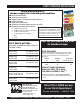
PARTS AND OPERATION MANUAL CONCRETE SAW © COPYRIGHT 2003, MULTIQUIP INC. MODEL FS 1 Revision #3 (04/24/03) MULTIQUIP INC.. PARTS DEPARTMENT: 18910 WILMINGTON AVE. 800-427-1244 CARSON, CALIFORNIA 90746 FAX: 800-672-7877 310-537-3700 SERVICE DEPARTMENT/TECHNICAL ASSISTANCE: 800-421-1244 800-478-1244 FAX: 310-537-3927 FAX: 310-631-5032 E-mail:mq@multiquip.com • www:multiquip.
PAGE 2 — MQ-WHITEMAN FS1 CONCRETE SAW — PARTS & OPERATION MANUAL — REV.
HERE'S HOW TO GET HELP PLEASE HAVE THE MODEL AND SERIAL NUMBER ON-HAND WHEN CALLING PARTS DEPARTMENT 800-427-1244 or 310-537-3700 FAX: 800-672-7877 or 310-637-3284 SERVICE DEPARTMENT 800-421-1244 FAX: 310- 537-4259 TECHNICAL ASSISTANCE 800-478-1244 FAX: 310- 631-5032 WARRANTY DEPARTMENT 888-661-4279, or 310-661-4279 FAX: 310- 537-1173 MQ-WHITEMAN FS1 CONCRETE SAW — PARTS & OPERATION MANUAL — REV.
TABLE OF CONTENTS Here's How To Get Help ........................................... 3 Table Of Contents .................................................... 4 Parts Ordering Procedures ...................................... 5 Safety Message Alert Symbols ............................. 6-7 Decals ...................................................................... 8 Rules for Safe Operation .....................................9-11 Dimensions ............................................................
PARTS ORDERING PROCEDURES When ordering parts, please supply the following information: ❒ ❒ ❒ ❒ ❒ ❒ ❒ Dealer account number Dealer name and address Shipping address (if different than billing address) Return fax number Applicable model number Quantity, part number and description of each part Specify preferred method of shipment: Note: Unless otherwise indicated by customer, all ✓ FedEx or UPS Ground orders are treated as “Standard Orders”, and will ✓ FedEx or UPS Second Day or Third Day ship within 24 hou
FS 1 CONCRETE SAW — SAFETY MESSAGE ALERT SYMBOLS FOR YOUR SAFETY AND THE SAFETY OF OTHERS! Safety precautions should be followed at all times when operating this equipment. Failure to read and understand the Safety Messages and Operating Instructions could result in injury to yourself and others. NOTE This Owner's Manual has been developed to provide complete instructions for the safe and efficient operations of the MQWhiteman FS 1 Concrete Saw.
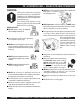
FS 1 CONCRETE SAW — SAFETY MESSAGE ALERT SYMBOLS Accidental Starting Respiratory Hazard ALWAYS place ON/OFF switch to OFF, remove key and/or disconnect the spark plug lead before servicing the engine or equipment. Ground the lead to prevent sparks that could ignite a fire. Over Speed Conditions ALWAYS wear approved respiratory protection. Sight and Hearing hazard NEVER tamper with the factory settings of the engine governor or settings.
FS 1 CONCRETE SAW — DECALS Machine Safety Decals The FS 1 Concrete Saw is equipped with a number of safety decals (Figure 1). These decals are provided for operator safety and maintenance information. The illustration shows these decals as they appear on the concrete saw. Should any of these decals become unreadable, replacements can be obtained from you dealer. Figure 1. FS 1 Concrete Saw Decal Placement PAGE 8 — MQ-WHITEMAN FS1 CONCRETE SAW — PARTS & OPERATION MANUAL — REV.
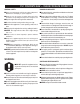
FS 1 CONCRETE SAW — RULES FOR SAFE OPERATION WARNING: Failure to follow instructions in this manual may lead to serious injury or even death! This equipment is to be operated by trained and qualified personnel only! This equipment is for industrial use only. The following safety guidelines should always be used when operating the MQ Whiteman FS 1 Concrete Saw: GENERAL SAFETY ■ DO NOT operate or service this equipment before reading this entire manual.
FS 1 CONCRETE SAW — RULES FOR SAFE OPERATION GENERAL SAFETY DIAMOND BLADE SAFETY ■ Always read, understand, and follow procedures in Operator’s Manual before attempting to operate equipment. ■ Use appropriate steel centered diamond blades manufactured for use on concrete saws. ■ Always be sure the operator is familiar with proper safety precautions and operating techniques before using the saw. ■ Always inspect diamond blades before each use.
FS 1 CONCRETE SAW — RULES FOR SAFE OPERATION Emergencies ■ Always know the location of the nearest fire extinguisher and first aid kit. Know the location of the nearest telephone. Also know the phone numbers of the nearest ambulance, doctor and fire department. This information will be invaluable in the case of an emergency. Maintenance Safety ■ NEVER lubricate components or attempt service on a running machine. ■ Always allow the machine a proper amount of time to cool before servicing.
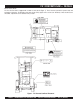
FS 1 CONCRETE SAW — DIMENSIONS Figure 2. FS 1 Concrete Saw Dimensions TABLE 1. DIMENSIONS REFERENCE LETTER DESCRIPTION DIMENSION (MM) A Max Height (Handle Bars Fully Raised) 50" (1270) B Max Height (Handle Bars Fully Lowered) 36" (914) C Max Length (Handle Bars Fully Raised & Front Pointer Lowered) 50" (1270) D Max Length (Handle Bars Fully Raised & Front Pointer Raised) 39" (991) E Max Length (Handle Bars Fully Lowered & Front Pointer Raised) 36.
FS 1 CONCRETE SAW — WEIGHTS Figure 3. FS 1 Concrete Saw Weights TABLE 2. WEIGHTS SAW DESCRIPTION WEIGHT (kgs) FS1-LE14 SAW, FS1, 14", PUSH, LESS ENGINE 160 (73) FS1-LE18 SAW, FS1, 18", PUSH, LESS ENGINE 165 (75) FS1-8H14 SAW, FS1, 14", PUSH, 8 HP HONDA 230 (104) FS1-8H18 SAW, FS1, 18", PUSH, 8 HP HONDA 235 (106) FS1-8K14 SAW, FS1, 14", PUSH, 8.5 HP KOHLER 230 (104) FS1-8K18 SAW, FS1, 18", PUSH, 8.
FS 1 CONCRETE SAW — BASIC COMPONENTS BASIC COMPONENTS Figure 4. FS 1 Concrete Saw Basic Components PAGE 14 — MQ-WHITEMAN FS1 CONCRETE SAW — PARTS & OPERATION MANUAL — REV.
FS 1 CONCRETE SAW — BASIC COMPONENTS BASIC COMPONENTS NO DESCRIPTION PAGE 1 2 3 4 5 6 7 8 UNDER CARRIAGE ASSEMBLY BLADE SHAFT ASSEMBLY FRAME ASSEMBLY BLADE COVER ASSEMBLY BLADE GUARD ASSEMBLIES WATER SYSTEM ASSEMBLY RAISE/LOWER ASSEMBLY GASOLINE ENGINE ASSEMBLIES SEE PAGE 38 SEE PAGE 40 SEE PAGE 42 SEE PAGE 44 SEE PAGE 46 SEE PAGE 48 SEE PAGE 50 SEE PAGE 52 MQ-WHITEMAN FS1 CONCRETE SAW — PARTS & OPERATION MANUAL — REV.
FS 1 CONCRETE SAW — BASIC ENGINE COMPONENTS Figure 5. Engine Controls and Components INITIAL SERVICING 5. The engine (Figure 5) must be checked for proper lubrication and filled with fuel prior to operation. Refer to the manufacturers Engine manual for instructions & details of operation and servicing. Fuel Valve Lever – OPEN to let fuel flow, CLOSE to stop the flow of fuel. 6. Choke Lever – Used in the starting of a cold engine, or in cold weather conditions. The choke enriches the fuel mixture. 1.
FS 1 CONCRETE SAW — GENERAL INFORMATION FAMILIARIZATION POWER PLANTS The MQWhiteman FS1 Series Concrete Saws are designed for wet or dry cutting utilizing diamond blades. They have been engineered for general and industrial flat sawing applications. The exceptional performance of these saws centers around simple operating features, top quality components, and committed attention to state-of-the-art manufacturing.
FS 1 CONCRETE SAW — GENERAL INFORMATION UNDER CARRIAGE SYSTEM MANUAL RAISE/LOWER SYSTEM A jig welded heavy steel gauge under carriage chassis assembly supports the saw in tracking, pivoting and stabilization. Two rear wheels (8" x 2.0" x 3/4") and two front wheels (4" x 2.0" x 3/4") supports the chassis. The entire assembly pivots about the rear carriage and is lubricated through 90-degree grease fitting in the rear axle tube.
FS 1 CONCRETE SAW — INSPECTION -ENGINE Before Starting 1. Read safety instructions at the beginning of manual. 2. Clean the SAW, removing dirt and dust, particularly the engine cooling air inlet, carburetor and air cleaner. 3. Check the air filter for dirt and dust. If air filter is dirty, replace air filter with a new one as required. 4. Check carburetor for external dirt and dust. Clean with dry compressed air. Figure 8.
FS 1 CONCRETE SAW — INSPECTION -BLADE WARNING Failure to thoroughly inspect the diamond blade (Figure 9) for operational safety could result in damage to the blade, the saw, and may cause injury to the user or others in the operating area. Figure 9. Diamond Blade 1. Drive Pin Hole – A commonly located hole located on the diamond blade core that prevents operational blade slippage between the inner & outer blade flanges (collars).
FS 1 CONCRETE SAW — INSPECTION -BLADE PLACEMENT WARNING 4. Diamond Blade – Ensure that the proper diamond blade has been selected for the job. Pay close attention to the directional arrows on the blade, clockwise for right-hand cutting and counter-clockwise for left-hand cutting, then place the blade onto the blade shaft, and ensure the arbor hole of the blade matches the diameter of the shaft. 5. Blade Drive Pin – Line up the blade drive pin with the inner flange (collar) pin hole.
FS 1 CONCRETE SAW — INSPECTION -BLADE PLACEMENT NOTE The following steps should be accomplished before using the FS1 on any cutting surface. Diamond Blade Placement Procedure The FS1 is equipped with an Raise/Lower assembly that is supported by the following components (Figure 11): ■ Raise/Lower Ball Handle (1) ■ Actuating Arm Lever (2) ■ Depth Pointer Bar (3) ■ Raise/Lower Scale (4) 1. Set the engine ON/OFF switch to the OFF position. 2. Place the FS1 saw on a stable level working surface. 2.
FS 1 CONCRETE SAW — INSPECTION -GUARDS, COVERS AND V-BELTS Guards and Covers Check V-belts and Cover CAUTION: WARNING NEVER operate the saw without blade guards and covers (Figures 12,13 and 14) in place. DO NOT operate with the front of the blade guard raised. The blade exposure cannot exceed 180 degrees during operations. Adhere to the safety guidelines of the American National Standards Institute (ANSI) B7.1 and B7.5.
FS 1 CONCRETE SAW — INSPECTION -GUARDS, COVERS AND V-BELTS 3. Check V-belt tension (Figure 16) by using a tension meter (6.0 - 9.0 lbs) against the inside belt at a mid point between the two pulleys, or by deflecting the center belt at a mid point 3/8” (10mm) - 1/2” (13mm). Figure 16. V-Belt Tension 4. DO NOT over or under tension the V-belts. Severe damage can occur to the saw and engine crank shaft if the belts are over tensioned.
FS 1 CONCRETE SAW— INITIAL START-UP CAUTION: DO NOT attempt to operate the saw until the D Safety, General Information and Inspection sections have been read and understood. Depending on engine manufacturer, operating steps may vary. See engine manufactures operating manual. The following start-up procedure makes reference to a HONDA engine. 1. Ensure the diamond blade has been mounted correctly and that it raised above the surface you about to saw.
FS 1 CONCRETE SAW — INITIAL START-UP 8. Grasp the starter grip (Figure 21) and slowly pull it out. The resistance becomes the hardest at a certain position, corresponding to the compression point. Pull the starter grip briskly and smoothly for starting. CAUTION: z DO NOT pull the starter rope all the way to the end. z DO NOT release the starter rope after pulling. Allow it to rewind as soon as possible.
FS 1 CONCRETE SAW — OPERATION Saw Alignment 1. The FS 1 employs a front and rear pointer (Figure 22) that has been precisely aligned with the diamond blade at the factory. Referencing the figure below, accurate tracking is accomplished by referencing the front and rear pointer tips over the cut line. Precise saw direction is accomplished by slight operator pressure against the handle bars. 5. Set the depth and saw only as the job conditions and specifications require.
FS 1 CONCRETE SAW — OPERATION Dry Saw Operation WARNING WARNING Engine components can generate extreme heat. Diamond Blades and Blade Speed The operator must wear the appropriate protective equipment and clothing while engaged in sawing. 1. Ensure the proper DRY Cutting blade is selected for the job. 2. The preferred method of sawing is to step cut in increments of 2” (51 mm). “ Step-cutting” provides the optimum opportunity for the blade to cut fast and last its longest.
FS 1 CONCRETE SAW — MAINTENANCE CAUTION: General maintenance practices are crucial to the performance and longevity of your saw. The extreme environments of sawing operations require routine cleaning, lubrication, belt tensioning, and inspection for wear and damage WARNING The following procedures devoted to maintenance can prevent serious saw damage or malfunctioning. Before servicing or inspection, ALWAYS park the saw on a level surface with the engine ON/OFF switch in “OFF” position. 4.
FS 1 CONCRETE SAW — MAINTENANCE Blade Shaft Bearing Replacement The FS 1 is supported by “tapped" base lock collar self-aligning blade shaft bearings. These heavy duty bearings support the 11/4 blade shaft, and have grease (zerk) points (Figures 24 and 25) conveniently located for service. 3. To loosen the tension on the two V-belts perform the following: z Remove the V-belt cover (Figure 14). z Loosen the engine adjustment bolts (Figure 26). z Position the engine to allow for slack in the V-belts.
FS 1 CONCRETE SAW — MAINTENANCE V-Belt Tension Check Check tension after first day of operation, then weekly/or 25 hours. Replace as required (see Figure 16). NEVER operate with less than 2 belts. The FS 1 is equipped with (2) premium A-27 V-belts for the 14inch model and (3) premimum A-27 V-belts belts for the 18-inch model which will provide optimum torque transfer. The saw must be operated with all V-belts, and must be adjusted collectively and properly to be effective.
FS 1 CONCRETE SAW — TROUBLESHOOTING (ENGINE) TABLE 6. ENGINE TROUBLESHOOTING SYMPTON Difficult to star t, "fuel is available, but no SPARK at spark plug". Difficult to star t, "fuel is available, and SPARK is present at the spark plug". Difficult to star t, "fuel is available, spark is present and compression is normal" Difficult to star t, "fuel is available, spark is present and compression is low" No fuel present at carburetor.
FS 1 CONCRETE SAW — TROUBLESHOOTING (ENGINE) TABLE 6. ENGINE TROUBLESHOOTING (CONTINUED) SYMPTON "Weak in power" compression is proper and does not misfire. POSSIBLE CAUSE SOLUTION Air cleaner not clean? Clean or replace air cleaner Improper level in carburetor? Check float adjustment, re-build carbureator. Defective Spark plug? Clean or replace spark plug. Defective Spark plug? "Weak in power" compression is proper but misfires. Engine overheats. Rotational speed fluctuates.
FS 1 CONCRETE SAW — TROUBLESHOOTING (BLADE) TABLE 7. BLADE TROUBLESHOOTING SYMPTON Blade slows or Stops cutting,still remains on blade. Blade does not cut straight and/or true. Blade discoloring, crackling and/or wearing excessively. POSSIBLE CAUSE SOLUTION Blade too hard for the material being cut. Consult Dealer or Multiquip for correct blade. Try cutting very soft material (sandstone, silica brick, cinder block) to "Redress" the blade. Engine Torgue diminished because of loose V-Belts.
FS 1 CONCRETE SAW — NOTE PAGE MQ-WHITEMAN FS1 CONCRETE SAW — PARTS & OPERATION MANUAL — REV.
FS 1 CONCRETE SAW — EXPLANATION OF CODE IN REMARKS COLUMN How to read the marks and remarks used in this parts book. Section 1: Items Found In the “Remarks” Column Serial Numbers-Where indicated, this indicates a serial number range (inclusive) where a particular part is used. Model Number-Where indicated, this shows that the corresponding part is utilized only with this specific model number or model number variant.
FS 1 CONCRETE SAW — SUGGESTED SPARE PARTS FS 1 CONCRETE SAW 1 TO 3 UNITS 1 to 3 Units Qty. ........ P/N .............................. Description 1 ............ 511329 ........................ SHAFT, BLADE S/N 200003 TO 200009 1 ............ 511659 ........................ SHAFT, BLADE S/N 2000102 ............ 511333 ........................ FLANGE, BLADE INSIDE 1 ............ 511332 ........................ FLANGE, BLADE OUTSIDE 2 ............ 492167 ........................ BEARING PILLOW BLOCK 1 ......
FS 1 CONCRETE SAW — UNDER CARRIAGE ASSY. UNDER CARRIAGE ASSY. PAGE 38 — MQ-WHITEMAN FS1 CONCRETE SAW — PARTS & OPERATION MANUAL — REV.
FS 1 CONCRETE SAW — UNDER CARRIAGE ASSY. UNDER CARRIAGE ASSY. NO PART NO PART NAME 1 2 3 4 5 6 7 8 9 9 10 11 12 13 14 15 16 17 17 18 10024 503078 0730 0948 503602 10024 511471 491704 511407 511661 8151 503111 511487 492586 503088 621 10176 512468 511311 511472 NUT, NYLOC 1/4-20 1 ROD, DEPTH ADJUSTMENT 1 SCREW, HHC 1/4-20 X 1 1 WASHER, FLAT 1/4 2 POINTER, DEPTH 1 NUT, NYLOC 1/2-13 2 TENSIONER, SPRING 1 ZERK FITTING 1 AXLE, REAR .............................................. 1 ....................
FS 1 CONCRETE SAW — BLADE SHAFT ASSY. BLADE SHAFT ASSY. PAGE 40 — MQ-WHITEMAN FS1 CONCRETE SAW — PARTS & OPERATION MANUAL — REV.
FS 1 CONCRETE SAW — BLADE SHAFT ASSY. BLADE SHAFT ASSY. NO PART NO PART NAME 1 2 3 4 5 6 7 7 8 9 9 10 11 11 12 13 14 15 16 17 17 511330 503803 511332 511333 511404 492167 511329 511659 492467 505205 512892 500194 511405 512896 511466 511331 504679 10133 490166 511501 511501 NUT, LEFT-HAND 1 PIN, BLADE DRIVE 3/8" X 1" 1 FLANGE, DRIVEN ASSY. 1 FLANGE, BLADE INSIDE 2 BUSHING, LEFT SIDE 1 BEARING, PILLOW BLOCK 2 SHAFT, BLADE ........................................ 1 ...............
FS 1 CONCRETE SAW — FRAME ASSY. FRAME ASSY. PAGE 42 — MQ-WHITEMAN FS1 CONCRETE SAW — PARTS & OPERATION MANUAL — REV.
FS 1 CONCRETE SAW — FRAME ASSY. FRAME ASSY.
FS 1 CONCRETE SAW — COVER ASSY. COVER ASSY. PAGE 44 — MQ-WHITEMAN FS1 CONCRETE SAW — PARTS & OPERATION MANUAL — REV.
FS 1 CONCRETE SAW — COVER ASSY. COVER ASSY. NO PART NO PART NAME 1 2 3 4 5 6 7 503012 592623 0655 492597 COVER, BELT WASHER, LOCK SCREW, HHC 5/16 - 18 X 3/4 WASHER, FLAT 5/16 503014 503114 COVER, BLADE FLANGE SCREW, HHC 5/16 - 18 X 3-1/2 QTY. REMARKS 1 4 2 6 2 1 2 MQ-WHITEMAN FS1 CONCRETE SAW — PARTS & OPERATION MANUAL — REV.
FS 1 CONCRETE SAW — BLADE GUARD ASSY. BLADE GUARD ASSY. PAGE 46 — MQ-WHITEMAN FS1 CONCRETE SAW — PARTS & OPERATION MANUAL — REV.
FS 1 CONCRETE SAW — BLADE GUARD ASSY. BLADE GUARD ASSY.
FS 1 CONCRETE SAW — WATER SYSTEM ASSY. WATER SYSTEM ASSY. PAGE 48 — MQ-WHITEMAN FS1 CONCRETE SAW — PARTS & OPERATION MANUAL — REV.
FS 1 CONCRETE SAW — WATER SYSTEM ASSY. WATER SYSTEM ASSY. NO 1 2 PART NO 0730 511431 PART NAME SCREW, HHC 1/4-20 X 1 CLAMP, 3/4 3 4 5 6 7 8 9 0948 491163 10024 491201 503124 491237 503108 WASHER, FLAT 1/4 FITTING, 1/2" X 90" PIPE NUT, NYLOC 1/4-20 FITTING, 1/2" NPT CONNECTOR FITTING, 1/2 NPT/ GARDEN HS BRASS VALVE, BALL COCK 1/2" NPT HOSE, 1/2 QTY. 4 2 REMARKS 4 2 4 1 1 1 1 MQ-WHITEMAN FS1 CONCRETE SAW — PARTS & OPERATION MANUAL — REV.
FS 1 CONCRETE SAW — MANUAL RAISE AND LOWER ASSY. MANUAL RAISE AND LOWER ASSY. PAGE 50 — MQ-WHITEMAN FS1 CONCRETE SAW — PARTS & OPERATION MANUAL — REV.
FS 1 CONCRETE SAW — MANUAL RAISE AND LOWER ASSY. MANUAL RAISE/LOWER ASSY. NO PART NO PART NAME 1 2 3 4 4910196 503013 503093 503094 KNOB, 3/8 NC LEVER WASHER, FLAT WASHER, COMPOSITE QTY. REMARKS 1 1 1 2 MQ-WHITEMAN FS1 CONCRETE SAW — PARTS & OPERATION MANUAL — REV.
FS 1 CONCRETE SAW — ENGINE ASSY. ENGINE ASSY. PAGE 52 — MQ-WHITEMAN FS1 CONCRETE SAW — PARTS & OPERATION MANUAL — REV.
FS 1 CONCRETE SAW — ENGINE ASSY. ENGINE ASSY. NO 1 1 1 1 1 2 2 3 PART NO PART NAME 492054 512891 500194 8.0 H.P. HONDA MODEL GX240K1QA2 8.5 H.P. KOLHER MODEL PA-951502 9.0 H.P. HONDA MODEL GX270K1QC9 12.0 H.P. KOHLER MODEL PA-941502 13.0 H.P. HONDA MODEL GX390K1QC9 PULLEY 2-GROOVE PULLEY 3-GROOVE KEY, 1/4 X 1- 3/4 QTY. REMARKS 1 1 1 1 1 1 1 1 MQ-WHITEMAN FS1 CONCRETE SAW — PARTS & OPERATION MANUAL — REV.
Effective: October 1, 2002 PAYMENT TERMS TERMS AND CONDITIONS OF SALE — PARTS 5. Terms of payment for parts are net 10 days. FREIGHT POLICY All parts orders will be shipped collect or prepaid with the charges added to the invoice. All shipments are F.O.B. point of origin. Multiquip’s responsibility ceases when a signed manifest has been obtained from the carrier, and any claim for shortage or damage must be settled between the consignee and the carrier.
NOTE PAGE MQ-WHITEMAN FS1 CONCRETE SAW — PARTS & OPERATION MANUAL — REV.
PARTS AND OPERATION MANUAL HERE'S HOW TO GET HELP PLEASE HAVE THE MODEL AND SERIAL NUMBER ON-HAND WHEN CALLING PARTS DEPARTMENT 800-427-1244 or 310-537-3700 FAX: 800-672-7877 or 310-637-3284 ^^^^^*^^^^^^^^^^^^^^^^^^^^^^^^^*^6668 SERVICE DEPARTMENT/TECHNICAL ASSISTANCE 800-478-1244 or 310-537-3700 FAX: 310- 537-4259 WARRANTY DEPARTMENT 888-661-4279, or 310-661-4279 FAX: 310- 537-1173 MAIN 800-421-1244 or 310-537-3700 FAX: 310-537-3927 MULTIQUIP INC.