PARTS AND OPERATION MANUAL PARTS AND OPERATION MANUAL MQ POWER TLG-12SPX WHISPER WATT AC GENERATOR © COPYRIGHT 2001, MULTIQUIP INC. TM (Standard) Revision #4 (03/08/05) S/N 5107226~ MULTIQUIP INC.. PARTS DEPARTMENT: 18910 WILMINGTON AVE. 800-427-1244 CARSON, CALIFORNIA 90746 FAX: 800-672-7877 SERVICE DEPARTMENT: 310-537-3700 800-421-1244 800-835-2551 FAX: 310-537-3927 FAX: 310-638-8046 E-mail:mq@multiquip.com • www:multiquip.
PAGE 2 — TLG-12SPX — PARTS AND OPERATION MANUAL (STD) — REV.
HERE'S HOW TO GET HELP PLEASE HAVE THE MODEL AND SERIAL NUMBER ON-HAND WHEN CALLING PARTS DEPARTMENT 800/427-1244 or 310/537-3700 FAX: 800/672-7877 or 310/637-3284 SERVICE DEPARTMENT 800/835-2551 or 310/537-3700 FAX: 310/638-8046 WARRANTY DEPARTMENT 800/835-2551 or 310/537-3700 FAX: 310/638-8046 MAIN 800/421-1244 or 310/537-3700 FAX: 310/537-3927 TLG-12SPX — PARTS AND OPERATION MANUAL (STD) — REV.
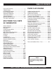
TABLE OF CONTENTS Here's How To Get Help ............................................... 3 Table Of Contents ........................................................ 4 Parts Ordering Procedures .......................................... 5 Rules for Safe Operation .......................................... 6-9 Towing and Transportation ......................................... 10 Trailer Safety Guidelines ....................................... 11-15 Trailer Wiring Diagram ...................................
PARTS ORDERING PROCEDURES ■ ■ ■ ■ ■ ■ ■ Dealer account number Dealer name and address Shipping address (if different than billing address) Return fax number Applicable model number Quantity, part number and description of each part Specify preferred method of shipment: • • • • UPS Ground UPS Second Day or Third Day* UPS Next Day* Federal Express Priority One (please provide us with your Federal Express account number)* • • Airborne Express* Truck or parcel post *Normally shipped the same day the order
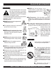
RULES FOR SAFE OPERATION CAUTION: Failure to follow instructions in this manual may lead to serious injury or even death! This equipment is to be operated by trained and qualified personnel only! This equipment is for industrial use only. ■ NEVER touch the hot exhaust manifold, muffler or cylinder. Allow these parts to cool before servicing engine or generator.
RULES FOR SAFE OPERATION CAUTION CAUTION: CAUTION CAUTION: DO NOT touch or open any of the below mentioned components while the generator is running. Always allow sufficient time for the engine and generator to cool before performing maintenance. ■ NEVER touch output terminals during operation. This is extremely dangerous. Always stop the machine when contact with the output terminals is required. CAUTION CAUTION: ■ Backfeed to a utility system can cause electrocution and/or property damage.
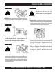
RULES FOR SAFE OPERATION Battery CAUTION CAUTION: Never over fill the battery with water above the upper limit. The battery contains acids that can cause injury to the eyes and skin. To avoid eye irritation, always wear safety glasses. Use well insulated gloves when picking up the battery. Use the following guidelines when handling the battery: ■ NEVER Run engine without air filter. Severe engine damage may occur. ■ Always service air cleaner frequently to prevent carburetor malfunction.
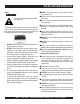
RULES FOR SAFE OPERATION Transporting ■ Always shutdown engine before transporting. ■ Tighten fuel tank cap securely. ■ Drain fuel when transporting generator over long distances or bad roads. ■ Always tie-down the generator during transportation by securing the generator. ■ If generator is mounted on a trailer, make sure trailer complies with all local and state safety transportation laws. See page 10 for basic towing procedures.
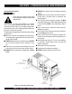
TLG-12SPX — TOWING RULES FOR SAFE OPERATION Towing Safety Precautions CAUTION : Check with your county or state safety towing regulations department before towing your generator. To reduce the possibility of an accident while transporting the generator on public roads, always make sure the trailer (Figure 1) that supports the generator and the towing vehicle are in good operating condition and both units are mechanically sound.
TLG-12SPX — TRAILER-SAFETY GUIDELINES CAUTION: ALWAYS make sure the trailer is in good operating condition. Check the tires for proper inflation and wear. Also check the wheel lug nuts for proper tightness. Explanation of Chart: This section is intended to provide the user with trailer service and maintenance information. The service and maintenance guidelines referenced in this section apply a wide range of trailers.
TLG-12SPX —TRAILER-SPECIFICATIONS Table 1. Specifications MODEL APPLICATION FU E L C E LL BRAKE SYSTEM GVWR FRAME LENGTH FRAME WIDTH JACK STAND TRLR-10W SDW225, SGW250,TLW300 NO NO 1900LB S 96" 50" 800LB . FULL TILT WHEEL TRLR-10 DCA10, TLG12, DCA-15 NO NO 1900LB S 96" 50" 800LB . FULL TILT WHEEL TRLR-10XF DCA10, TLG-12, DCA15, TLW-300 52 GAL NO 1900LB S 96" 50" 800LB . FULL TILT WHEEL TRLR-225W WELDERS, D A 7000S S NO NO 2200LB S 85" 42" 800LB .
TLG-12SPX —TRAILER-SPECIFICATIONS Table 1. Specifications (Con't) MODEL COUPLER TIRES WHEELS AXLE HUBS SUSPENSION ELECTRICAL TRLR-10W 2" B A LL C LA S S 2 ADJUSTABLE 175-13C 13"X4.50" 2200# 2X 2 5 LUG 3 LE A F 4 WIRE LOOM W/ 4 POLE FLAT TRLR-10 2" B A LL C LA S S 2 ADJUSTABLE 175-13C 13"X4.5" 2200#2X 2 5 LUG 3 LE A F 4 POLE FLAT TRLR-10XF 2" B A LL C LA S S 2 ADJUSTABLE 175-13C 13"X4.
TLG-12SPX —TRAILER SAFETY GUIDELINES Tires/Wheels/Lug Nuts Tires and wheels are a very important and critical components of the trailer. When specifying or replacing the trailer wheels it is important the wheels, tires, and axle are properly matched. CAUTION: DO NOT attempt to repair or modify a wheel. DO NOT install in inner tube to correct a leak through the rim.
TLG-12SPX —TRAILER SAFETY GUIDELINES Table 3. Suspension Torque Requirements Item Torque (Ft.-Lbs.) 3/8" U-BOLT MIN-30 MAX-35 7/16" U-BOLT MIN-45 MAX-60 1/2" U-BOLT MIN-45 MAX-60 SHACKLE BOLT SNUG FIT ONLY. PARTS MUST ROTATE FREELY. SPRING EYE BOLT LOCKING NUTS OR COTTER PINS ARE PROVIDED TO RETAIN NUT-BOLT ASSEMBLY. MIN-30 MAX-50 SHOULDER TYPE SHACKLE BOLT Lug Nut Torque Requirements It is extremely important to apply and maintain proper wheel mounting torque on the trailer.
TLG-12SPX —TRAILER WIRING DIAGRAM NOTE: LIGHTS ARE ORIENTED FROM THE DRIVER’S SEAT PAGE 16 — TLG-12SPX — PARTS AND OPERATION MANUAL (STD) — REV.
TLG-12SPX — GENERATOR DECALS The TLG-12SPX generator is equipped with a number of safety decals. These decals are provided for operator safety and maintenance information. The illustration below and on the preceding pages show the decals as they appear on the machine. Should any of these decals become unreadable, replacements can be obtained from your dealer. TLG-12SPX — PARTS AND OPERATION MANUAL (STD) — REV.
TLG-12SPX — GENERATOR DECALS PAGE 18 — TLG-12SPX — PARTS AND OPERATION MANUAL (STD) — REV.
TLG-12SPX — SPECIFICATIONS Table 5. Specifications Generator Specifications Model TLG-12SPX Type Revolving field, self ventilated, drip proof, single bearing generator Armature Connection Series Standby Output 13KW Prime Output 12KW Voltage 240V or 480V Frequency 60 Hz Speed 3600 rpm Power Factor 1 Aux. AC Power Single Phase, 60 Hz Voltage 120/240 V Sound level dB(A) Full load 23 feet 67 Engine Specifications Model Isuzu 3LB1 Type 4 Cycle, water-cooled,swirl chamber No.
TLG-12SPX — GENERAL INFORMATION TLG-12SPX FAMILIARIZATION Open Delta Excitation System Generator The TLG-12SPX generator is equipped with the state of the The MQ Power Model TLG-12SPX is a 9.6 kW generator art "Open-Delta" excitation system. The open delta system that is designed as a high quality portable power source for consist of an electrically independent winding wound among telecom sites, lighting facilities, power tools, submersible stationary windings of the AC output section.
TLG-12SPX — MAJOR COMPONENTS Figure 4. Major Components TLG-12SPX — PARTS AND OPERATION MANUAL (STD) — REV.
TLG-12SPX — DIMENSIONS (TOP, SIDE AND FRONT) Figure 5. Dimensions PAGE 22 — TLG-12SPX — PARTS AND OPERATION MANUAL (STD) — REV.
NOTE PAGE TLG-12SPX — PARTS AND OPERATION MANUAL (STD) — REV.
TLG-12SPX — CONTROL PANEL Figure 6. Control Panel PAGE 24 — TLG-12SPX — PARTS AND OPERATION MANUAL (STD) — REV.
TLG-12SPX — CONTROL PANEL The definitions below describe the controls and functions of the TLG-12SPX "Control Panel " (Figure 6). 1. Circuit Breaker – This three-pole, 65 amp breaker is provided to protect the UNV voltage output terminals from overload. 2. Frequency Meter – Indicates the output frequency in hertz (Hz). Normally 60 Hz ±1 Hz . 3. AC Voltmeter – Indicates the single phase output voltage present at the UNV terminals. 4.
TLG-12SPX — ENGINE OPERATING/OUTPUT TERMINAL PANEL Figure 7. Engine Control/ Output Terminal Panel PAGE 26 — TLG-12SPX — PARTS AND OPERATION MANUAL (STD) — REV.
TLG-12SPX — ENGINE OPERATING/OUTPUT TERMINAL PANEL The definitions below describe the controls and functions of the TLG-12SPX " Engine Operating/Output Terminal Panel” (Figure 7). 1. Idle Control Switch - This switch is used to change the idle of the engine from low to high (on some models) 2. Throttle Handle - This handle is used for initial start up of the engine. 3. GFCI Receptacle - This is a 20A, 120V parallel slot with a U-ground. 4. NEMA receptacle - These output receptacles are locking type.
TLG-12SPX — OUTPUT TERMINAL PANEL TLG-12SPX FAMILIARIZATION The Output Terminal panel is provided with the following: One GFCI 120 Volt Receptacle, 20 Amp (single-phase) Ground Terminal (for GFCI receptacle) Main Circuit Breaker 50 amps GFCI Circuit Breaker 20 amps NEMA L530R Output Receptacle NEMA L630R Output Receptacle NEMA CS6369 Output Receptacle NEMA L5-30R Output Receptacle The L5-30R receptacle supplies 30 amps at 120 volts. A 30 amp circuit breaker helps protect any load being used.
TLG-12SPX — OUTPUT TERMINAL PANEL Figure 10. TLG12SPX Output Terminal Panel Figure 11. 5-20R Receptacles Details Figure 12. NEMA Receptacles Details TLG-12SPX — PARTS AND OPERATION MANUAL (STD) — REV.
TLG-12SPX — INSTALLATION Outdoor Installation Install the generator in a location where it will not be exposed to rain or sunshine. Make sure the generator is on secure level ground so it cannot slide or shift around. Also install the generator so the exhaust will not be discharged in the direction of nearby homes. CAUTION : An electric shock may happen when vibrators are used.
TLG-12SPX — INSTALLATION Figure 13. Typical Generator Grounding Application TLG-12SPX — PARTS AND OPERATION MANUAL (STD) — REV.
TLG-12SPX — PRE-SETUP General Inspection Prior to Operation Extension Cable The TLG-12SPX generator has been thoroughly inspected and accepted prior to shipment from the factory. However, be sure to check for damaged parts or components, or loose nuts and bolts, which could have occurred in transit. When electric power is to be provided to various tools or loads at some distance from the generator, extension cords are normally used.
TLG-12SPX — PRE-SETUP Lubrication Oil Fill the engine crankcase with lubricating oil through the filler hole, but do not overfill. Make sure the generator is level. With the dipstick inserted all the way, but without being screw into the filler hole, verify that the oil level is maintained between the two notches (Figure 14) on the dipstick. See Table 7 for proper selection of engine oil. Fuel Fill the fuel tank with clean and fresh diesel fuel. DO NOT fill the tank beyond capacity.
TLG-12SPX — PRE-SETUP CAUTION : Cleaning the Radiator The engine may overheat if the radiator fins become When adding coolant or antifreeze to the overloaded with dust or debris. Periodically clean the radiator radiator, do not remove the radiator cap fins with compressed air. Cleaning inside the machine is until the unit has completely cooled. dangerous, so clean only with the engine turned off and the battery disconnected. Air Cleaner Day-to-day addition of coolant is done from the reserve tank.
TLG-12SPX — PRE-SETUP/LOAD APPLICATION Battery This unit is of negative ground. DO NOT connect in reverse. Always maintain battery fluid level between the specified marks. Battery life will be shortened, if the fluid level is not properly maintained. Add only distilled water when replenishment is necessary. The battery is sufficiently charged if the specific gravity of the battery fluid is 1.28 (at 68° F). If the specific gravity should fall to 1.
TLG-12SPX —LOAD APPLICATION The power factor of this generator is 1.0. See Table 10. below when connecting loads. Table 10. Power Factor By Load Type Of Load Power Factor Single-phase induction motors 0.4 - 0.75 Electric heaters, incandescent lamps 1.0 Fluorescent lamps, mercury lamps 0.4 - 0.9 Electronic devices, communication equipment 1.0 Common power tools 0.
TLG-12SPX — START UP PROCEDURE Starting the Generator 1. Set the Throttle switch to “Start/Idle”(Figure 19). Before Starting Engine 1. Check the lubricating oil level prior to starting the engine. Make sure the generator is level. The oil level must be maintained between two notches on the dipstick. 2. When there is not enough lubricating oil, fill the crankcase with high grade motor oil. Use a high quality detergent oil classified CC or higher (See Table Figure 19. Throttle Handle (Idle) 7 on page 31).
TLG-12SPX — SHUTDOWN PROCEDURE 5. The generator's frequency meter (Figure 23) displays the 60 cycle output frequency in HERTZ. 8. Set the circuit breaker to “ON”. Observe the generator's ammeter (Figure 27) and verify it reads the anticipated amount of current with respect to the load. The ammeter will only display a current reading if the load is in use. 20 40 0 60 75 A Figure 23. Frequency Meter (Hz) Figure 27. Ammeter (Load) 6. The generator's voltage meter (Figure 24) displays the 9.
NOTE PAGE TLG-12SPX — PARTS AND OPERATION MANUAL (STD) — REV.
TLG-12SPX — MAINTENANCE General Inspection Cleaning the Fuel Strainer Prior to each use, the generating set should be cleaned and inspected for deficiencies. Check for loose, missing or damaged nuts, bolts or other fasteners. Also check for fuel or oil leaks. Clean the fuel strainer if it contains dust or water. Remove dust or water in the strainer cap and wash it in diesel. Securely fasten the fuel strainer cap so that fuel will not leak.
TLG-12SPX — MAINTENANCE INSPECTION / MAINTENANCE 10 Hrs DAILY Check Engine Fluid Levels X Check Air Cleaner X Check Battery Acid Level X Check Fan Belt Condition X Check for Leaks X Check for Loosening of Parts X Check Water Separator GENERATOR 500 Hrs 1000 Hrs X 1 ENGINE 250 Hrs Replace Engine Oil and Filter * X Clean Air Filter X Drain Bottom of Fuel Tank X Clean Unit, Inside and Outside X Change Fuel Filter *2 X Clean Radiator and Check Coolant Protection Level X Replace
TLG-12SPX — ENGINE WIRING DIAGRAM PAGE 42 — TLG-12SPX — PARTS AND OPERATION MANUAL (STD) — REV.
TLG-12SPX — GENERATOR WIRING DIAGRAM TLG-12SPX — PARTS AND OPERATION MANUAL (STD) — REV.
TLG-12SPX — TROUBLESHOOTING (ENGINE) Practically all breakdowns can be prevented by proper handling and maintenance inspections, but in the event of a breakdown, use the tables shown for diagnosis based on the Engine Troubleshooting (Table 11). If the problem cannot be remedied, consult our company's business office or service plant. TABLE 11. ENGINE TROUBLESHOOTING SYMPTOM Engine does not start. POSSIBLE PROBLEM SOLUTION No fuel? Replenish fuel. Air in the fuel system? Bleed system.
TLG-12SPX — TROUBLESHOOTING (ENGINE) TABLE 11. ENGINE TROUBLESHOOTING (CONTINUED) SYMPTOM Engine revolution is not smooth. Either white or blue exhaust gas is observed. Either black or dark gray exhaust gas is observed. Deficient output. POSSIBLE PROBLEM SOLUTION Fuel filter clogged or dirty? Clean or change. Air cleaner clogged? Clean or change. Fuel leak due to loose injection pipe retaining nut? Tighten nut. Injection pump malfunctioning? Repair or replace.
TLG-12SPX — TROUBLESHOOTING (GENERATOR) Practically all breakdowns can be prevented by proper handling and maintenance inspections, but in the event of a breakdown, use the tables shown for diagnosis based on the Engine and Generator Troubleshooting (Table 12). If the problem cannot be remedied, consult our company's business office or service plant. TABLE 17. GENERATOR TROUBLESHOOTING SYMPTOM POSSIBLE PROBLEM SOLUTION AC Voltmeter defective? Check output voltage using a voltmeter.
NOTE PAGE TLG-12SPX — PARTS AND OPERATION MANUAL (STD) — REV.
EXPLANATION OF CODE IN REMARKS COLUMN How to read the marks and remarks used in this parts book. Items Found In the “Remarks” Column Serial Numbers-Where indicated, this indicates a serial number range (inclusive) where a particular part is used. Model Number-Where indicated, this shows that the corresponding part is utilized only with this specific model number or model number variant.
TLG-12SPX — SUGGESTED SPARE PARTS TLG-12SPX W/ISUZU 3LB1 DIESEL ENGINE 1 TO 3 UNITS Qty. P/N Description 1 ......... 0601806537 ..... CIRCUIT BREAKER 1 ......... 0601820663 ..... AUTOMATIC VOLTAGE REGULATOR 1 ......... 0601840073 ..... RHEOSTAT VOLTAGE REGULATOR 1 ......... 0601840121 ..... KNOB RHEOSTAT 1 ......... 8522015503 ..... RADIATOR HOSE (UPPER) 1 ......... 8971076820 ..... RADIATOR HOSE (LOWER) 5 ......... 8944567411 ..... OIL FILTER 5 ......... 8970488490 ..... FUEL FILTER 5 .........
TLG-12SPX --- GENERATOR ASSY. GENERATOR ASSY. PAGE 50 — TLG-12SPX — PARTS AND OPERATION MANUAL (STD) — REV.
TLG-12SPX --- GENERATOR ASSY. GENERATOR ASSY. NO. PART NO.
TLG-12SPX --- CONTROL PANEL ASSY. CONTROL PANEL ASSY. PAGE 52 — TLG-12SPX — PARTS AND OPERATION MANUAL (STD) — REV.
TLG-12SPX --- CONTROL PANEL ASSY. CONTROL PANEL ASSY. NO. PART NO. ITEM QTY. REMARKS 1 8521827203 CONTROL PANEL 1 2 0605010060 HINGE ........................................................ 2 ......... B1075L 3 0027103010 MACHINE SCREW .................................... 8 ......... REPLACES 0021103010 4 0021806030 MACHINE SCREW 2 5 0601800408 FREQUENCY METER ............................... 1 ......... FCF5 220V 45~65Hz 6 0601805745 AC AMMETER ........................................... 1 .........
TLG-12SPX --- CONTROL PANEL ASSY. CONTROL PANEL ASSY. PAGE 54 — TLG-12SPX — PARTS AND OPERATION MANUAL (STD) — REV.
TLG-12SPX --- CONTROL PANEL ASSY. CONTROL PANEL ASSY. NO. PART NO. ITEM QTY. REMARKS 26 0027104012 MACHINE SCREW 8 003000400 HEX.NUT ................................................... 8 ......... REPLACES 0207004000 27 0601815109 GROUND TERMINAL ................................. 1 ......... T-381 28 0601842347 RESISTOR ................................................. 1 ......... FF20W30 OHM 29 0027104012 MACHINE SCREW 2 30 0601823204 RECTIFIER ................................................ 1 .........
TLG-12SPX ENGINE AND RADIATOR ASSY. ENGINE AND RADIATOR ASSY. PAGE 56 — TLG-12SPX — PARTS AND OPERATION MANUAL (STD) — REV.
TLG-12SPX ENGINE AND RADIATOR ASSY. ENGINE AND RADIATOR ASSY. NO. PART NO. ITEM QTY. REMARKS 1 8520150004 ENGINE ........................................... 1 ......... ISUZU 3LB1 1-1 8943142633 CARTRIDGE, OIL FILTER ............... 1 ......... REPLACES 0602041210 060201140 FAN BELT ........................................ 1 ......... ISUZU 8970687980 2 8525112104 ENGINE FOOT 2 3 0012810020 HEX. HEAD BOLT 8 4 7605419004A RUBBER SUSPENSION .................. 2 ......... REPLACES 7605419004 5 0207010000 HEX.
TLG-12SPX --- BATTERY ASSY. BATTERY ASSY. PAGE 58 — TLG-12SPX — PARTS AND OPERATION MANUAL (STD) — REV.
TLG-12SPX --- BATTERY ASSY. BATTERY ASSY. NO. PART NO. 1 0167306531 2 7612251004 3 8522250004 4 7612252004 5 0037808000 6 0040008000 7 031108160 10 11 12 0602220310 0602220311 0602220600 ITEM QTY. REMARKS BATTERY ......................................... 1 ......... 65D31R BATTERY SHEET 1 BATTERY BAND 1 BATTERY BOLT 2 WING NUT 2 LOCK WASHER 2 PLAIN WASHER .............................. 2 ......... REPLACES 0041208000 BATTERY CABLE 1 BATTERY CABLE 1 TERMINAL ASSY. ........................... 1 .........
TLG-12SPX --- MUFFLER ASSY. MUFFLER ASSY. PAGE 60 — TLG-12SPX — PARTS AND OPERATION MANUAL (STD) — REV.
TLG-12SPX --- MUFFLER ASSY. MUFFLER ASSY. NO. PART NO. 1 8522310102 2 011008020 3 8522330003 4 8522332004 5 8522331004 6 011008020 7 0017106016 8 3312320004 9 011208035 10 897042080 11 1502336004 12 020108060 13 011208035 ITEM QTY. REMARKS MUFFLER 1 HEX. HEAD BOLT ............................ 4 ......... REPLACES 0017108020 EXHAUST PIPE 1 EXHAUST PIPE 1 EXHAUST PIPE 1 HEX. HEAD BOLT ............................ 2 ......... REPLACES 0017108020 HEX. HEAD BOLT 1 PIPE BAND 2 HEX. HEAD BOLT ....................
TLG-12SPX --- FUEL TANK ASSY. FUEL TANK ASSY. PAGE 62 — TLG-12SPX — PARTS AND OPERATION MANUAL (STD) — REV.
TLG-12SPX --- FUEL TANK ASSY. FUEL TANK ASSY. NO. PART NO. 1 1-1 1-2 1-3 1-4 2 3 4 5 6 7 8 9 10 11 12 13 14 15 16 17 18 19 20 21 22 23 24 25 26 27 8525500003 0810105900 0810105900 0267700200 0605515005 8525525003 011008020 8525523004 0805003404 011008020 020108060 1555527004 7812014003 0802011104 0150000018 0017106016 0199900830 0605515094 8525546014 011208025 8971041891 8970713480 0017108065 0602023175 0199900350 0199900300 0199900400 0199700500 0199700270 0605515094 0605515096 1615511204 ITEM QTY.
TLG-12SPX --- ENCLOSURE ASSY. ENCLOSURE ASSY. PAGE 64 — TLG-12SPX — PARTS AND OPERATION MANUAL (STD) — REV.
TLG-12SPX --- ENCLOSURE ASSY. ENCLOSURE ASSY. NO. PART NO.
TLG-12SPX --- ENCLOSURE ASSY. ENCLOSURE ASSY. THE PART NUMBER DEFAULT IS SCARLET COLOR. INDICATE THE LETTERS BELOW TO INDICATE DIFFERENT COLOR OF UNIT: MQW-WHITE THE SERIAL NUMBER MAY BE REQUIRED. PAGE 66 — TLG-12SPX — PARTS AND OPERATION MANUAL (STD) — REV.
TLG-12SPX --- ENCLOSURE ASSY. ENCLOSURE ASSY. NO. PART NO.
TLG-12SPX --- RUBBER SEAL ASSY. RUBBER SEAL ASSY. PAGE 68 — TLG-12SPX — PARTS AND OPERATION MANUAL (STD) — REV.
TLG-12SPX --- RUBBER SEAL ASSY. RUBBER SEAL ASSY. NO. PART NO. ITEM 56 57 58 59 60 61 62 63 64 65 66 0227600590 0227600835 0229400560 0229400550 0229400840 0229400220 0229400590 0229200210 0229200615 0226900570 0229200680 RUBBER SEAL RUBBER SEAL RUBBER SEAL RUBBER SEAL RUBBER SEAL RUBBER SEAL RUBBER SEAL RUBBER SEAL RUBBER SEAL RUBBER SEAL RUBBER SEAL QTY. REMARKS 2 2 2 1 2 2 1 2 2 1 1 TLG-12SPX — PARTS AND OPERATION MANUAL (STD) — REV.
TLG-12SPX --- DECALS DECAL ASSY. PAGE 70 — TLG-12SPX — PARTS AND OPERATION MANUAL (STD) — REV.
TLG-12SPX --- DECALS DECAL ASSY. NO. PART NO. ITEM 1-1 2-1 2-2 2-3 2-4 2-5 2-6 2-7 3-1 3-2 3-3 3-4 3-5 4-1 4-2 4-3 4-4 4-5 4-6 4-7 4-8 4-9 4-10 4-11 4-12 4-13 4-14 4-15 4-16 4-17 4-18 4-19 4-20 DECAL; OPERATING PROCEDURE ................... 1 ....... S1742B DECAL; VOLTAGE REGULATOR .......................... 1 ....... S3737 DECAL; CIRCUIT BREAKER ............................... 1 ....... S-3031 DECAL; STARTER SWITCH ................................ 1 ....... S4753 DECAL; SPEED CONTROL HANDLE ............
ISUZU 3LB1 — CYLINDER HEAD COVER ASSY. CYLINDER HEAD COVER ASSY. PAGE 72 — TLG-12SPX — PARTS AND OPERATION MANUAL (STD) — REV.
ISUZU 3LB1 — CYLINDER HEAD COVER ASSY. CYLINDER HEAD COVER ASSY. NO PART NO PART NAME QTY. REMARKS 1 8970655484 CYLINDER HEAD COVER 1 4 8941332075 OIL FILLER CAP ............................. 1 .......... INCL. ITEMS W/* 5* 8941236231 OIL FILLER GASKET 1 28 0280806200 BOLT 9 69 8970655472 GASKET 1 TLG-12SPX — PARTS AND OPERATION MANUAL (STD) — REV.
ISUZU 3LB1 — CYLINDER HEAD ASSY. CYLINDER HEAD ASSY. PAGE 74 — TLG-12SPX — PARTS AND OPERATION MANUAL (STD) — REV.
ISUZU 3LB1 — CYLINDER HEAD ASSY. CYLINDER HEAD ASSY. NO PART NO 1 8971056750 8971633991 2 8970439332 3A 8944637840 3B 8970369591 4* 8970317490 5A* 8970317101 5B* 8970317110 7A* 1096000112 7B* 1096000051 10 8971065490 11 8970346333 12 8970853900 14 5093000650 15 028088160 25* 511190090 27* 8970446351 36 8941105591 41 0280808160 50 8970946410 103 5096050050 168 8970853890 PART NAME QTY. REMARKS CYLINDER HEAD ASSY. .................. 1 ........ OCT. 1993 TO OCT. 1996; INCL. ITEMS W/* CYLINDER HEAD ASSY. .....
ISUZU 3LB1 — CYLINDER BLOCK ASSY. CYLINDER BLOCK ASSY. PAGE 76 — TLG-12SPX — PARTS AND OPERATION MANUAL (STD) — REV.
ISUZU 3LB1 — CYLINDER BLOCK ASSY. CYLINDER BLOCK ASSY. NO. PART NO. PART NAME 1 8971061943 CYLINDER BLOCK ASSY. ..................................... 1 .......... DEC. 1993 TO MAR. 1995; INCL. ITEMS W/* CYLINDER BLOCK ASSY. ..................................... 1 .......... APR. 1995 TO MAR. 1997 CYLINDER BLOCK ASSY. ..................................... 1 .......... APR. 1997~ SEALING CUP 4 SEALING CUP 1 BOLT 8 OIL GALLERY PLUG, PT 1/8 1 OIL GALLERY PLUG, PT 1/8 SQ.
ISUZU 3LB1 — OIL PAN AND LEVEL GAUGE ASSY. OIL PAN AND LEVEL GAUGE ASSY. PAGE 78 — TLG-12SPX — PARTS AND OPERATION MANUAL (STD) — REV.
ISUZU 3LB1 — OIL PAN AND LEVEL GAUGE ASSY. OIL PAN AND LEVEL GAUGE ASSY. NO. 1 PART NO. 8971322101 2 3* 4* 23 24 8970439421 1096230570 9096620120 8971351410 8971378360 PART NAME QTY. REMARKS OIL PAN ASSY. ............................................... 1 .......... REPLACES 8970439362; INCL .ITEMS W/* OIL LEVER GAUGE 1 GASKET 1 OIL DRAIN PLUG 1 BOLT ............................................................. 16 .......... REPLACES 0280806140 OIL PAN NUT ................................................
ISUZU 3LB1 — CAMSHAFT AND VALVE ASSY. CAMSHAFT AND VALVE ASSY. PAGE 80 — TLG-12SPX — PARTS AND OPERATION MANUAL (STD) — REV.
ISUZU 3LB1 — CAMSHAFT AND VALVE ASSY. CAMSHAFT AND VALVE ASSY. NO. 1 4 5 6 34* 53 55 57 65 68 71 78A 78B 78B 81 83 88 89 91 92A PART NO.
ISUZU 3LB1 — CRANKSHAFT, PISTON AND FLYWHEEL ASSY. CRANKSHAFT, PISTON AND FLYWHEEL ASSY. PAGE 82 — TLG-12SPX — PARTS AND OPERATION MANUAL (STD) — REV.
ISUZU 3LB1 — CRANKSHAFT, PISTON AND FLYWHEEL ASSY. CRANKSHAFT, PISTON AND FLYWHEEL ASSY. NO 1 7 12 18 28 35* 38 40 42 43 48 59 63 67 68 71 73 83 84 85# 86# 88# 126 PART NO 8970405203 8970395820 8971078930 8971093721 8970345920 8944196021 8970232680 8941333281 5115990023 8943860790 8942016410 8941347920 8971768880 8970871050 8970346090 8971137620 8971412040 5122710141 8944017510 8970200670 8941375220 8941075501 8942409020 8944017501 PART NAME QTY. REMARKS CRANKSHAFT 1 METAL KIT 1 FLYWHEEL .................
ISUZU 3LB1 — TIMING GEAR AND FLYWHEEL HOUSING ASSY. TIMING GEAR AND FLYWHEEL HOUSING ASSY. PAGE 84 — TLG-12SPX — PARTS AND OPERATION MANUAL (STD) — REV.
ISUZU 3LB1 — TIMING GEAR AND FLYWHEEL HOUSING ASSY. TIMING GEAR AND FLYWHEEL HOUSING ASSY. NO. 1 2 40 103 134 172 175 185 211 226 367 531 532* PART NO. 8970851331 8970470233 0911502080 5096250790 9041108600 9041108500 8970447862 5096250940 0280806200 0281810250 8941277030 0280808800 0280908600 8944256852 8941236231 PART NAME QTY.
ISUZU 3LB1 — INLET MANIFOLD ASSY. INLET MANIFOLD ASSY. PAGE 86 — TLG-12SPX — PARTS AND OPERATION MANUAL (STD) — REV.
ISUZU 3LB1 — INLET MANIFOLD ASSY. INLET MANIFOLD ASSY. NO. 303 652 653 PART NO. 8970346140 9041106160 0911502060 PART NAME AIR PIPE DUCT STUD NUT QTY. 1 2 2 REMARKS TLG-12SPX — PARTS AND OPERATION MANUAL (STD) — REV.
ISUZU 3LB1 — EXHAUST MANIFOLD ASSY. EXHAUST MANIFOLD ASSY. PAGE 88 — TLG-12SPX — PARTS AND OPERATION MANUAL (STD) — REV.
ISUZU 3LB1 — EXHAUST MANIFOLD ASSY. EXHAUST MANIFOLD ASSY. NO. 1 2 15 16 18 84 PART NO. 8970345881 8970376822 0280808400 0280808700 9041108200 0911502080 8970420280 PART NAME EXHAUST MANIFOLD GASKET BOLT, M8X40 FLANGE BOLT, M8X70 FLANGE STUD NUT GASKET, EXHAUST PIPE QTY. 1 1 1 1 4 2 1 REMARKS TLG-12SPX — PARTS AND OPERATION MANUAL (STD) — REV.
ISUZU 3LB1 — VENTILATION ASSY. VENTILATION ASSY. PAGE 90 — TLG-12SPX — PARTS AND OPERATION MANUAL (STD) — REV.
ISUZU 3LB1 — VENTILATION ASSY. VENTILATION ASSY. NO. 13 32 43A 43B 43C 59 62 73 130A 130B 135 PART NO. 9039104100 5097070051 8971056801 8971025191 8971056811 8971025191 8941271440 8942493171 8942386100 1097070870 8970833300 5111790520 8943295490 PART NAME QTY. REMARKS SCREW 4 CLIP 4 PCV HOSE 1 PCV HOSE 1 PCV HOSE .................................................... 1 ........ OCT. 1993 TO OCT. 1997 PCV HOSE ................................................... 1 ........ NOV.
ISUZU 3LB1 — WATER PUMP AND CORROSION RESISTOR ASSY. WATER PUMP AND CORROSION RESISTOR ASSY. PAGE 92 — TLG-12SPX — PARTS AND OPERATION MANUAL (STD) — REV.
ISUZU 3LB1 — WATER PUMP AND CORROSION RESISTOR ASSY. WATER PUMP AND CORROSION RESISTOR ASSY. NO. 2 24 36 40 42 58 144 PART NO. 8971632590 0280808450 0280908600 0280808400 0911502080 9041108400 5096050050 1096050500 PART NAME QTY. REMARKS WATER PUMP ASSY. .......... 1 ..................... REPLACES 8970698821 BOLT, M8X45 FLANGE 1 BOLT, M8X60 FLANGE 2 BOLT, M8X40 FLANGE 2 NUT 2 STUD 1 HEATER PLUG 1 THERMOSTAT PLUG 1 TLG-12SPX — PARTS AND OPERATION MANUAL (STD) — REV.
ISUZU 3LB1 — THERMOSTAT AND HOUSING ASSY. THERMOSTAT AND HOUSING ASSY. PAGE 94 — TLG-12SPX — PARTS AND OPERATION MANUAL (STD) — REV.
ISUZU 3LB1 — THERMOSTAT AND HOUSING ASSY. THERMOSTAT AND HOUSING ASSY. NO. 1 49 50 64 PART NO. 8943255131 8971606540 8970958411 0280808200 8943259561 PART NAME QTY. REMARKS THERMOSTAT ........................... 1 ................ APR. 1992 TO DEC. 1996 THERMOSTAT ........................... 1 ................ JAN. 1997~ WATER OUTLET PIPE 1 BOLT 2 GASKET 1 TLG-12SPX — PARTS AND OPERATION MANUAL (STD) — REV.
ISUZU 3LB1 — FAN AND FAN BELT ASSY. FAN AND FAN BELT ASSY. PAGE 96 — TLG-12SPX — PARTS AND OPERATION MANUAL (STD) — REV.
ISUZU 3LB1 — FAN AND FAN BELT ASSY. FAN AND FAN BELT ASSY. NO. 1 24A 24B 36 38 80 96 112 PART NO. 8970967090 0208006120 0280808220 8970407640 8971604370 8970634001 5136741040 0280808200 8970384030 PART NAME QTY. REMARKS COOLING FAN ....................... 1 ................... D=330-6-BLOW BOLT, M6X12 2 BOLT, M8X22 FLANGE 4 BELT, L=826 ........................... 1 ................... APR. 1992 TO AUG. 1996 BELT, L=815 ........................... 1 ................... SEPT.
ISUZU 3LB1 — FUEL INJECTION ASSY. FUEL INJECTION ASSY. PAGE 98 — TLG-12SPX — PARTS AND OPERATION MANUAL (STD) — REV.
ISUZU 3LB1 — FUEL INJECTION ASSY. FUEL INJECTION ASSY. NO. 1 2 29 30 31 32* 33* 35*# 36*# 43*# 44*# 47*# 49 50 51 63 121 140*# PART NO.
ISUZU 3LB1 — FUEL FILTER AND BRACKET ASSY. FUEL FILTER AND BRACKET ASSY. PAGE 100 — TLG-12SPX — PARTS AND OPERATION MANUAL (STD) — REV.
ISUZU 3LB1 — FUEL FILTER AND BRACKET ASSY. FUEL FILTER AND BRACKET ASSY. NO. 1 2* 26* PART NO. 8971041891 8970713480 8941551830 PART NAME QTY. REMARKS FUEL FILTER ASSY. ................. 1 ................ INCL. ITEMS W/* FUEL FILTER ELEMENT KIT 1 GASKET 1 TLG-12SPX — PARTS AND OPERATION MANUAL (STD) — REV.
ISUZU 3LB1 — FUEL PUMP AND PIPE ASSY. FUEL PUMP AND PIPE ASSY. PAGE 102 — TLG-12SPX — PARTS AND OPERATION MANUAL (STD) — REV.
ISUZU 3LB1 — FUEL PUMP AND PIPE ASSY. FUEL PUMP AND PIPE ASSY. NO. 1 9* 34* 57* 215* PART NO. 8942411792 9019106280 8942336550 8942336570 8942389070 PART NAME QTY. REMARKS FUEL PUMP ASSY. .................. 1 ................ INCL. ITEMS W/* BOLT 2 RUBBER 2 WASHER 2 COLLAR 2 TLG-12SPX — PARTS AND OPERATION MANUAL (STD) — REV.
ISUZU 3LB1 — OIL FILTER ASSY. OIL FILTER ASSY. PAGE 104 — TLG-12SPX — PARTS AND OPERATION MANUAL (STD) — REV.
ISUZU 3LB1 — OIL FILTER ASSY. OIL FILTER ASSY. NO. 2 PART NO. 8943142633 PART NAME OIL FILTER ELEMENT QTY. 1 REMARKS TLG-12SPX — PARTS AND OPERATION MANUAL (STD) — REV.
ISUZU 3LB1 — OIL PUMP AND OIL STRAINER ASSY. OIL PUMP AND OIL STRAINER ASSY. PAGE 106 — TLG-12SPX — PARTS AND OPERATION MANUAL (STD) — REV.
ISUZU 3LB1 — OIL PUMP AND OIL STRAINER ASSY. OIL PUMP AND OIL STRAINER ASSY. NO. 1 13 23* 26 29* 51 61 85* 102 119* 120* 121* 132 151* PART NO. 8970488094 0280808300 9081606160 8970448430 0280806300 0280806500 8970439410 0280808160 8971096790 1096234960 8942446550 8941046150 8941145120 8971133320 8942355671 5824100361 8970448133 PART NAME QTY. REMARKS OIL PUMP ASSY. ...................... 1 ................. INCL.
ISUZU 3LB1 — ELECTRICAL CONTROL ASSY. ELECTRICAL CONTROL ASSY. PAGE 108 — TLG-12SPX — PARTS AND OPERATION MANUAL (STD) — REV.
ISUZU 3LB1 — ELECTRICAL CONTROL ASSY. ELECTRICAL CONTROL ASSY. NO. 1 2 4 7 16 23 46 89 177 238 292 603 613 729 PART NO. 8970489652 8970489701 0281812300 9091114080 0280810700 0911502100 8942481610 8941679410 8970701303 8971830140 9095720140 9091505080 8941268220 8970912901 8971163140 8971461050 8970633010 PART NAME QTY. REMARKS STARTER ASSY. 1 GENERATOR ASSY. 1 BOLT 2 NUT 1 BOLT 1 NUT 1 GLOW PLUG RELAY 1 SWITCH 1 SOLENOID ASSY. .................... 1 ........... APR. 1992 TO JUL. 1998 SOLENOID ASSY. .....
ISUZU 3LB1 — STARTER COMP. ASSY. STARTER COMP. ASSY. PAGE 110 — TLG-12SPX — PARTS AND OPERATION MANUAL (STD) — REV.
ISUZU 3LB1 — STARTER COMP. ASSY. STARTER COMP. ASSY. NO. PART NO. PART NAME QTY.
ISUZU 3LB1 — INJ. PUMP COMP. ASSY. INJ. PUMP COMP. ASSY. PAGE 112 — TLG-12SPX — PARTS AND OPERATION MANUAL (STD) — REV.
ISUZU 3LB1 — INJ. PUMP COMP. ASSY. INJ. PUMP NO. 6 7 9 10 14 19 21 23 58 62 63 64 68 69 82 109 117 118 134 181 COMP. ASSY. PART NO.
ISUZU 3LB1 — INJ. PUMP COMP. ASSY. INJ. PUMP COMP. ASSY. PAGE 114 — TLG-12SPX — PARTS AND OPERATION MANUAL (STD) — REV.
ISUZU 3LB1 — INJ. PUMP COMP. ASSY. NJ. PUMP COMP. ASSY. NO. PART NO. PART NAME QTY. REMARKS 193 8941289550 8941289560 8941289570 8941289580 8941289590 8941289600 8941289610 8970833500 SHIM ......................................... 1 ................ T=3.80 SHIM ......................................... 1 ................ T=3.85 SHIM ......................................... 1 ................ T=3.90 SHIM ......................................... 1 ................ T=3.95 SHIM ........................
ISUZU 3LB1 — TIMING CHAIN CASE ASSY. TIMING CHAIN CASE ASSY. PAGE 116 — TLG-12SPX — PARTS AND OPERATION MANUAL (STD) — REV.
ISUZU 3LB1 — TIMING CHAIN CASE ASSY. TIMING CHAIN CASE ASSY. NO. 1 5 6A 6B 6C 7 16 18 21 22A 22B 24 25 27 28 29 30 31 32 34 35 36 37 39 40 43 44 45 46A 46B 46C 47 48 49 50 52 53 54 PART NO.
ISUZU 3LB1 — TIMING CHAIN CASE ASSY. TIMING CHAIN CASE ASSY. PAGE 118 — TLG-12SPX — PARTS AND OPERATION MANUAL (STD) — REV.
ISUZU 3LB1 — TIMING CHAIN CASE ASSY. TIMING CHAIN CASE ASSY. NO. PART NO. PART NAME 55 56 57 58 8970346383 9082136250 9091854040 8970624222 8971485480 1096050500 8971062050 8971062051 8970395841 8970164410 9091605040 9091607040 9091854030 8943176381 9091505080 9081604360 8970837140 8970392644 5111290060 9095612530 8970395461 9091105080 8970388021 8944546150 8971059090 SHIFTER 1 SHAFT 1 SNAP RING 1 FLOATING LEVER .....................1 ...................... APR. 1992 TO JUN. 1996 FLOATING LEVER .......
ISUZU 3LB1 —AIR CLEANER ASSY. AIR CLEANER ASSY. PAGE 120 — TLG-12SPX — PARTS AND OPERATION MANUAL (STD) — REV.
ISUZU 3LB1 — AIR CLEANER ASSY. AIR CLEANER ASSY. NO. 1 2* 6* 89* 90* 91* 139 PART NO. 8941251130 9142170620 5142150140 9142191410 8941591510 5142170040 8970497220 PART NAME QTY. REMARKS CLEANER ASSY. ..................... 1 .................. INCL. ITEMS W/* WING NUT 1 AIR CLEANER FILTER 1 INDICATOR 1 CUP 1 CLAMP 1 AIR CLEANER BAND 2 TLG-12SPX — PARTS AND OPERATION MANUAL (STD) — REV.
ISUZU 3LB1 — SWITCH AND RELAY ASSY. SWITCH AND RELAY ASSY. PAGE 122 — TLG-12SPX — PARTS AND OPERATION MANUAL (STD) — REV.
ISUZU 3LB1 — SWITCH AND RELAY ASSY. SWITCH AND RELAY ASSY. NO. 58 288 424 434* PART NO. 8970444180 5825500290 5825500290 1823160070 PART NAME QTY. REMARKS IGNITION SWITCH ................... 1 ................ INCL. ITEMS W/* SAFETY RELAY 1 RELAY 2 STARTER SWITCH KEY 1 TLG-12SPX — PARTS AND OPERATION MANUAL (STD) — REV.
TERMS AND CONDITIONS OF SALE — PARTS Effective: July 1, 2000 4. PAYMENT TERMS Terms of payment for parts are net 10 days. FREIGHT POLICY All parts orders will be shipped collect or prepaid with the charges added to the invoice. All shipments are F.O.B. point of origin. Multiquip’s responsibility ceases when a signed manifest has been obtained from the carrier, and any claim for shortage or damage must be settled between the consignee and the carrier. Freight is at the sender’s expense.
NOTE PAGE TLG-12SPX — PARTS AND OPERATION MANUAL (STD) — REV.
PARTS AND OPERATION MANUAL PARTS AND OPERATION MANUAL HERE'S HOW TO GET HELP PLEASE HAVE THE MODEL AND SERIAL NUMBER ON-HAND WHEN CALLING © COPYRIGHT 2001, MULTIQUIP INC. PARTS DEPARTMENT 800/427-1244 or 310/537-3700 FAX: 800/672-7877 or 310/637-3284 SERVICE DEPARTMENT 800/835-2551 or 310/537-3700 FAX: 310/638-8046 WARRANTY DEPARTMENT 800/835-2551 or 310/537-3700 FAX: 310/638-8046 MAIN 800/421-1244 or 310/537-3700 FAX: 310/537-3927 MULTIQUIP INC.. PARTS DEPARTMENT: 18910 WILMINGTON AVE.