
User's Manual


PAGE 28 — DCA250SSI/DCA250SSIU GENERATOR • OPERATION AND PARTS MANUAL — REV. #0 (01/12/11)
OUTPUT TERMINAL PANEL CONNECTIONS
UVWO TERMINAL OUTPUT VOLTAGES
Various output voltages can be obtained using the UVWO
output terminal lugs. The voltages at the terminals are
dependent on the placement of the jumpers plates (6) on
the Voltage Change-Over Board and the adjustment of
the Voltage Regulator Control Knob.
Remember the voltage change-over board determines the
range of the output voltage and can be confi gured in two
different positions that provide 6 different output voltages
at the UVWO output terminals. The generator is shipped
from the factory in the 240V confi guration. The voltage
regulator (VR) allows the user to increase or decrease the
selected voltage.
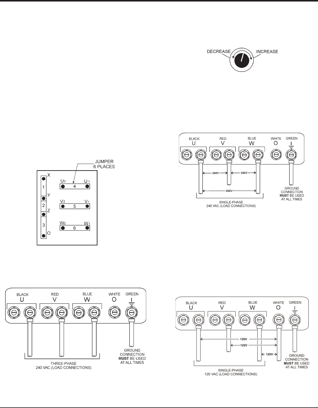
3Ø-240V UVWO Terminal Output Voltages
1. Jumper the voltage change-over board for 240V
operation as shown in Figure 18.
Figure 18. Voltage Change-Over Board 240V
Confi guration
2. Connect the load wires to the UVWO terminals as
shown in Figure 19.
Figure 19. UVWO Terminal Lugs
3. Turn the voltage regulator knob (Figure 20) clockwise
to increase voltage output, turn counterclockwise to
decrease voltage output. Use voltage regulator
adjustment knob whenever fi ne tuning of the output
voltage is required
Figure 20. Voltage Regulator Knob
1Ø-240V UVWO Terminal Output Voltages
1. Make sure the voltage change-over board is jumpered
for 240V operation as shown in Figure 18.
2. Connect the load wires to the UVWO terminals as
shown in Figure 21.
Figure 21. UVWO Terminal Lugs 1Ø-240V
Connections
1Ø-120V UVWO Terminal Output Voltages
1. Make sure the voltage change-over board is jumpered
for 240V operation as shown in Figure 18.
2. Adjust voltage regulator knob (Figure 20) for an output
of 208V to obtain 120V at the UVWO terminals.
3. Connect the load wires to the UVWO terminals as
shown in Figure 22.
Figure 22. UVWO Terminal Lugs 1Ø-120V
Connections