PARTS AND OPERATION MANUAL PARTS AND OPERATION MANUAL Table of Contents © COPYRIGHT 2000, MULTIQUIP INC. MQ POWER MODEL DCA-150SSKII PORTABLE GENERATOR Revision #2 (05/08/01) MULTIQUIP INC. PARTS DEPARTMENT: 18910 WILMINGTON AVE. 800-427-1244 CARSON, CALIFORNIA 90746 FAX: 800-672-7877 SERVICE DEPARTMENT: 310-537-3700 800-421-1244 800-835-2551 FAX: 310-537-3927 FAX: 310-638-8046 E-mail:mq@multiquip.com • www:multiquip.
Table of Contents PAGE 2 —DCA-150SSKII— PARTS AND OPERATION MANUAL — REV.
Table of Contents HERE'S HOW TO GET HELP PLEASE HAVE THE MODEL AND SERIAL NUMBER ON-HAND WHEN CALLING PARTS DEPARTMENT 800/427-1244 or 310/537-3700 FAX: 800/672-7877 or 310/637-3284 SERVICE DEPARTMENT 800/835-2551 or 310/537-3700 FAX: 310/638-8046 WARRANTY DEPARTMENT 800/835-2551 or 310/537-3700 FAX: 310/638-8046 MAIN 800/421-1244 or 310/537-3700 FAX: 310/537-3927 DCA-150SSKII — PARTS AND OPERATION MANUAL— REV.
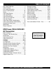
TABLE OF CONTENTS Here's How To Get Help ...........................................3 Table Of Contents ....................................................4 Parts Ordering Procedures ......................................5 Rules For Safe Operation .................................... 6-9 Towing ....................................................................10 Trailer Safety Guidlines ..........................................11 Trailer Specifications ........................................
Table of Contents PARTS ORDERING PROCEDURES ■ ■ ■ ■ ■ ■ ■ Dealer account number Dealer name and address Shipping address (if different than billing address) Return fax number Applicable model number Quantity, part number and description of each part Specify preferred method of shipment: • • • • UPS Ground UPS Second Day or Third Day* UPS Next Day* Federal Express Priority One (please provide us with your Federal Express account number)* • • Airborne Express* Truck or parcel post *Normally shipped the
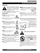
Table of Contents RULES FOR SAFE OPERATION CAUTION: Failure to follow instructions in this manual may lead to serious injury or even death! This equipment is to be operated by trained and qualified personnel only! This equipment is for industrial use only. The following safety guidelines should always be used when operating the DCA-150SSKII portable generator: GENERAL SAFETY ■ DO NOT operate or service this equipment before reading this entire manual.
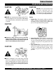
Table of Contents RULES FOR SAFE OPERATION CAUTION: CAUTION: DO NOT touch or open any of the below mentioned components while the generator is running. Always allow sufficient time for the engine and generator to cool before performing maintenance. ■ DO NOT touch output terminals during operation. This is extremely dangerous when your hands are wet. Always stop the machine when contact with the output terminals is required. Radiator 1.
Table of Contents RULES FOR SAFE OPERATION Battery CAUTION: Never over fill the battery with water above the upper limit. ■ NEVER Run engine without an air filter. Severe engine damage may occur. ■ Always service air cleaner frequently to prevent carburetor malfunction. ■ Always disconnect the battery before performing service on the generator. The battery contains acids that can cause injury to the eyes and skin. To avoid eye irritation, always wear safety glasses.
Table of Contents RULES FOR SAFE OPERATION Transporting ■ Always shutdown engine before transporting. ■ Tighten fuel tank cap securely. Maintenance Safety ■ NEVER lubricate components or attempt service on a running generator. ■ Drain fuel when transporting generator over long distances or bad roads. ■ Always allow the engine proper amount of time to cool before servicing. ■ Always tie-down the generator during transportation by securing the generator. ■ Keep the generator in proper running condition.
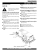
Table of Contents DCA-150SSKII — TOWING ■ ALWAYS attach trailer's safety chain to bumper of towing vehicle. Towing Safety Precautions CAUTION : Check with your county or state safety towing regulations department before towing your generator. To reduce the possibility of an accident while transporting the generator on public roads, always make sure that the trailer that supports the generator and the towing vehicle are in good operating condition and both units are mechanically sound.
Table of Contents DCA-150SSKII — TRAILER-SAFETY GUIDELINES CAUTION: 7. Coupler - Type of hitch used on the trailer for towing. 8. Tire Size - Indicates the diameter of the tire in inches ALWAYS make sure the trailer is in good (10,12,14, etc.), and the width in millimeters operating condition. Check the tires for (175,185,205, etc.). The tire diameter must match the proper inflation and wear. Also check the diameter of the tire rim. wheel lug nuts for proper tightness. 9.
Table of Contents DCA-150SSKII — TRAILER-SPECIFICATIONS Table 1. Specifications MOD EL APPLIC ATION FU E L C E LL B R AK E SYSTEM GVWR FR AME LEN GTH FR AME WID TH JAC K STAN D TR LR -10-15 TLG-12, D C A15, TLW-300 NO NO 1900LB S 96" 50" 800LB . FULL TILT WHEEL TR LR -10X TLG-12, D C A15, TLW-300 NO NO 1900LB S 96" 50" 800LB . FULL TILT WHEEL TR LR -10XF TLG-12, D C A15, TLW-300 51 GAL NO 1900LB S 96" 50" 800LB .
Table of Contents DCA-150SSKII — TRAILER-SPECIFICATIONS Table 1. Specifications (Con't) MODEL COUPLER TIRES WHEELS AXLE HUBS SUSPENSION ELECTRICAL TRLR-10-15W 2" B A LL C LA S S 2 ADJUSTABLE 175-13C 13"X4.50" 2200# 2X 2 5 LUG 3 LE A F 4 WIRE LOOM W/ 4 POLE FLAT TRLR-10X 2" B A LL C LA S S 2 ADJUSTABLE 175-13C 13"X4.5" 2200#2X 2 5 LUG 3 LE A F 4 POLE FLAT TRLR-10XF 2" B A LL C LA S S 2 ADJUSTABLE 175-13C 13"X4.
Table of Contents DCA-150SSKII — TRAILER BRAKING SYSTEM Brakes If your trailer has a braking system, the brakes should be inspected the first 200 miles of operation. This will allow the brake shoes and drums to seat properly. After the first 200 mile interval, inspect the brakes every 3,000 miles. If driving over rough terrain, inspect the brakes more frequently. Electric Brakes Electrically actuated brakes (Figure 2) are similar to hydraulic brakes.
Table of Contents DCA-150SSKII — TRAILER BRAKING SYSTEM Figure 2. Electrical Brake Components Hydraulic/Air/Surge Brakes Hydraulic brakes (Figure 3) should not require any special attention with the exception of routine maintenance such as shoe and lining replacement. These brakes can be adjusted in the same manner as electric brakes. Brake lines should be periodically checked for cracks, kinks, or blockage.
Table of Contents DCA-150SSKII — TRAILER TIRES & SUSPENSION Tires/Wheels/Lug Nuts Tires and wheels are a very important and critical components of the trailer. When specifying or replacing the trailer wheels it is important the wheels, tires, and axle are properly matched. CAUTION: DO NOT attempt to repair or modify a wheel. DO NOT install an inner tube to correct a leak through the rim.
Table of Contents DCA-150SSKII — TRAILER TIRES & SUSPENSION Table 3. Suspension Torque Requirements Item Torque (Ft.-Lbs.) 3/8" U-BOLT MIN-30 MAX-35 7/16" U-BOLT MIN-45 MAX-60 1/2" U-BOLT MIN-45 MAX-60 SHACKLE BOLT SNUG FIT ONLY. PARTS MUST ROTATE FREELY. SPRING EYE BOLT LOCKING NUTS OR COTTER PINS ARE PROVIDED TO RETAIN NUT-BOLT ASSEMBLY.
Table of Contents DCA-150SSKII — TRAILER WIRING DIAGRAMS NOTE: LIGHTS ARE ORIENTED FROM THE DRIVER’S SEAT PAGE 18 —DCA-150SSKII— PARTS AND OPERATION MANUAL — REV.
Table of Contents DCA-150SSKII — TRAILER-BRAKE TROUBLESHOOTING Table 5. Electric Brake Troubleshooting Symptom Possible Cause Solution No Brakes or Intermittent Brakes Any open circuits or broken wires? Find and correct. Any short circuits? Find and correct. Faulty controller? Test and correct. Any loose connections? Find and repair. Ground wire secure? Find and secure. Grease or oil on magnets or linings? Clean or replace. Connections corroded? Clean and correct cause of corrosion.
Table of Contents DCA-150SSKII — TRAILER-BRAKE TROUBLESHOOTING Table 6. Hydraulic Brake Troubleshooting Symptom Possible Cause Solution No Brakes Brake line broken or kinked? Repair or replace. Weak Brakes or Brakes Pull to One Side Brake lining glazed? Reburnish or replace. Trailer overloaded? Correct weight. Brake drums scored or grooved? Machine or replace. Tire pressure correct? Inflate all tires equally. Tires unmatched on the same axle? Match tires.
Table of Contents DCA-150SSKII — OPERATION AND SAFETY DECALS Machine Safety Decals The DCA-150SSKII generator is equipped with a number of safety decals. These decals are provided for operator safety and maintenance information. The illustration below and on the preceding page shows these decals as they appear on the machine. Should any of these decals become unreadable, replacements can be obtained from your dealer. DCA-150SSKII — PARTS AND OPERATION MANUAL— REV.
Table of Contents DCA-150SSKII — OPERATION AND SAFETY DECALS PAGE 22 —DCA-150SSKII— PARTS AND OPERATION MANUAL — REV.
Table of Contents DCA-150SSKII — SPECIFICATIONS Table 7. Speci fi cati ons Generator Speci fi cati ons Model D C A-150SSKII Type Revolvi ng fi eld, self venti lated, open protected type synchronous generator Armature C onnecti on Star w ith N eutral Zig Zag Phase 3 Si ngle Standby Output 165 KVA (132 KW) 96K W Pri me Output 150 KVA (120 KW) 87K W Voltage 240V or 480V 240V Frequency 60 Hz S peed 1800 rpm Power Factor 0.8 1 Aux.
Table of Contents DCA-150SSKII — GENERAL INFORMATION DCA-150SSKII FAMILIARIZATION Generator The MQ Power Model DCA-150SSKII is a 120 kW generator that is designed as a high quality portable (requires a trailer for transport) power source for telecom sites, lighting facilities, power tools, submersible pumps and other industrial and construction machinery. Microprocessor Controlled Alarm System The DCA-150SSKII generator is equipped with various alarms and LED status indicators.
NOTE PAGE DCA-150SSKII — PARTS AND OPERATION MANUAL— REV.
Table of Contents DCA-150SSKII — MAJOR COMPONENTS Figure 6. Major Components PAGE 26 —DCA-150SSKII— PARTS AND OPERATION MANUAL — REV.
Table of Contents DCA-150SSKII — DIMENSIONS (TOP, SIDE, AND REAR) Figure 7. Dimensions DCA-150SSKII — PARTS AND OPERATION MANUAL— REV.
Table of Contents DCA-150SSKII — CONTROL PANEL Figure 8. Control Panel PAGE 28 —DCA-150SSKII— PARTS AND OPERATION MANUAL — REV.
Table of Contents DCA-150SSKII — CONTROL PANEL The definitions below describe the controls and functions of the DCA-150SSKII " Control Panel "(Figure 8). 1. Frequency Meter – Indicates the output frequency in hertz (Hz). Normally 60 Hz ±1 Hz . 2. AC Ammeter – Indicates the amount of current the load is drawing from the generator. 3.
Table of Contents DCA-150SSKII — ENGINE OPERATING PANEL Figure 10. Engine Operating Panel PAGE 30 —DCA-150SSKII— PARTS AND OPERATION MANUAL — REV.
Table of Contents DCA150SSKII — ENGINE OPERATING PANEL The definitions below describe the controls and functions of the DCA-150SSKII " Engine Operating Panel "(Figure 10). 1. Tachometer – Indicates engine speed in RPM’s for 60 Hz operation. This meter should indicate 1800 RPM’s when the rated load is applied. In addition a built in hour meter will record the number of operational hours that the generator has been in use. 2.
Table of Contents DCA-150SSKII — OUTPUT TERMINAL PANEL OVERVIEW OUTPUT TERMINAL PANEL FAMILIARIZATION The “Output Terminal Panel” is provided with the following: " Three 240/139V output receptacles, 50 amp " Two 120V input receptacles, 20 amp " 3 Load Circuit Breakers 265V @65 amps " 2 Load GFCI Circuit Breakers 265V@ 20amps Connecting Load Loads can be connected to the generator by the UNV Lugs or the convienience receptacles. (See figure 13).
Table of Contents DCA-150SSKII — OUTPUT TERMINAL PANEL OVERVIEW NOTE Legs O and Ground are considered Bonded Grounds. FIGURE 14. Output Terminal Panel DCA-150SSKII — PARTS AND OPERATION MANUAL— REV.
Table of Contents DCA-150SSKII — OUTPUT TERMINAL PANEL OVERVIEW Output Terminal Panel Available Voltages A wide range of voltages are available to supply load to many different applications. Voltages may be selected by using the voltage selector switch and how you hookup your hard wire connection to the generator. To obtain some of the voltages listed, fine adjustment with the Voltage Regulator on the control panel is necessarry.
Table of Contents DCA-150SSKII — OUTPUT TERMINAL PANEL OVERVIEW How to read the output terminal guages. The guages and knobs on the control panel DO NOT effect the generator output in any fashion. They are there to simply help the operator observe how much power is being supplied produced at the UVWO legs.
Table of Contents DCA-150SSKII — OUTPUT TERMINAL PANEL OVERVIEW 240/120V Hard Wire Hookup 480/240V Hard Wire Hookup The output terminal panel, when suppling single phase 120 volts, will provide three legs available with 333.3 amps each on three different circuits. (See Figure 21 below.) The voltage selector switch must be set at the single phase 240/120V position. (See figure 20 below.) The output terminal panel, when suppling single phase 240 volts, will provide one leg only with 166.7 amps available.
Table of Contents DCA-150SSKII — OUTPUT TERMINAL PANEL OVERVIEW Voltage Selector Switch- 3 Phase 480/277V Position The following are additional voltages available when the voltage selector switch is in the 3 phase 480/277V position. (See figure 24 below.) Single Phase: 480V, 440V, or 416 Volt The following connection, with the voltage selector switch locked into the 3 phase 480/277V position (See Figure 24), can offer SINGLE PHASE power at 480V, 440V, or 416V.
Table of Contents DCA-150SSKII — OUTPUT TERMINAL PANEL OVERVIEW Voltage Selector Switch- 3 Phase 240/139V Position The following are additional voltages available when the voltage selector switch is in the 3 phase 240/139V position. (See Figure 29 below.) Single Phase: 240V, 220V, or 208 Volt The following connection, with the voltage selector switch locked into the 3 phase 240/139V position (See Figure 29), can offer SINGLE PHASE power at 240V, 220V, or 208V.
Table of Contents DCA-150SSKII — OUTPUT TERMINAL PANEL OVERVIEW Voltage Selector Switch- Single Phase 240/120V Position The following are additional voltages available when the voltage selector switch is in the single phase 240/120V position. (See Figure 34 below.) Single Phase: 120 Volt The following connection, with the voltage selector switch locked into the single phase 240/120V position (See Figure 34), will offer SINGLE PHASE power at 120V.
Table of Contents Outdoor Installation Install the generator in a location where it will not be exposed to rain or sunshine. Make sure that the generator is on secure level ground so it cannot slide or shift around. Also install the generator so the exhaust will not be discharged in the direction of nearby homes. DCA-150SSKII — INSTALLATION CAUTION : An electric shock is apt to happen when vibrators are used.
Table of Contents DCA-150SSKII — INSTALLATION Figure 38. Typical Generator Grounding Application CAUTION : Always check Local, State, and Federal laws before grounding generator set. DCA-150SSKII — PARTS AND OPERATION MANUAL— REV.
Table of Contents DCA-150SSKII — PRE-SETUP General Inspection Prior to Operation The DCA-150SSKII generator has been thoroughly inspected and accepted prior to shipment from the factory. However, be sure to check for damaged parts or components, or loose nuts and bolts, which could have occurred in transit. Extension Cable When electric power is to be provided to various tools or loads at some distance from the generator, extension cords are normally used.
Table of Contents DCA-150SSKII — PRE-SETUP Lubrication Oil Fill the engine crankcase with lubricating oil through the filler hole, but do not overfill. Make sure the generator is level. With the dipstick inserted all the way, but without being screw into the filler hole, verify that the oil level is maintained between the two notches (Figure 39) on the dipstick. See Table 3 for proper selection of engine oil. Fuel Fill the fuel tank with clean and fresh diesel fuel. DO NOT fill the tank beyond capacity.
Table of Contents DCA-150SSKII — PRE-SETUP CAUTION : When adding coolant or antifreeze to the radiator, do not remove the radiator cap until the unit has completely cooled. Day-to-day addition of coolant is done from the reserve tank. When adding coolant to the radiator, DO NOT remove the radiator cap until the unit has completely cooled. See Table 13. for engine, radiator, and reserve tank coolant capacities.
Table of Contents DCA-150SSKII — PRE-SETUP Battery Cable Installation ALWAYS be sure the battery cables (Figure 41) are properly connected to the battery terminals as shown below. The RED cable is connected to the positive terminal of the battery, and the BLACK cable is connected to the negative terminal of the battery. CAUTION : Inadequate battery connections may cause poor starting of the generator, and create other malfunctions.
Table of Contents DCA-150SSKII — LOAD APPLICATION CAUTION: Single Phase Load Always be sure to check the nameplate on the generator and equipment to insure the wattage, amperage and frequency requirements are satisfactorily supplied by the generator for operating the equipment. Generally, the wattage listed on the nameplate of the equipment is its rated output.
Table of Contents DCA-150SSKII — GENERATOR START-UP PROCEDURE (MANUAL) WARNING: The engine's exhaust contains harmful emissions. ALWAYS ventilate the exhaust when operating inside tunnels, excavations or buildings. Direct exhaust away from nearby Before Starting Engine 2. Once it is determined if commercial power is required, connect the load to the UNV terminals as shown in Figure 43. These terminals can be found on the output terminal panel, see page 33, Figure 14.
Table of Contents DCA-150SSKII — GENERATOR START-UP PROCEDURE (MANUAL) 4. Close all engine enclosure doors (Figure 45). 7. After engine starts, verify that the "Engine Running" status LED (Figure 49) on the Microprocessor Engine Control Module (MPEC) display is "ON" (lit). Figure 45. Engine Enclosure Doors 5. When starting the generator in COLD weather conditions, press and hold the engine preheat button (Figure 46) until the pre-heat lamp (Figure 47) is lit (ON). Figure 49.
Table of Contents DCA-150SSKII — GENERATOR START-UP PROCEDURE (MANUAL) 11. The generator's frequency meter (Figure 53) displays the 60 cycle output frequency in HERTZ. 14. The engine oil pressure gauge (Figure 57) will indicate the oil pressure (kg/ cm2) of the engine. Under normal operating conditions the oil pressure should be approximately 25 psi. Figure 53. Frequency Meter (Hz) 12. The generator's voltage meter (Figure 54) displays the 120 VAC in VOLTS.
Table of Contents DCA-150SSKII — GENERATOR START-UP PROCEDURE (AUTO) 17. After the engine has been running for a few minutes, look at the status LED’S on the "MPEC" display (Figure 9) and check it for any abnormal conditions. If any abnormal conditions exist, shut down the engine and take corrective action to solve the problem. 18. If there are no abnormal problems shown on the “MPEC" LED display, turn the MAIN, GFCI and LOAD circuit breakers to their ON position (Figure 60).
Table of Contents DCA-150SSKII — GENERATOR SHUT-DOWN PROCEDURE Engine Shutdown To shut-down the generator use the following procedure: 1. Place both the MAIN, GFCI and LOAD circuit breakers to the "OFF position" 6. Verify that the "Engine Running" status LED (Figure 66) on the Microprocessor Engine Control Module (MPEC) display is "OFF" (not lit). 2. Turn the Engine Throttle Handle (Figure 63)to the left and push in to set the speed to 'low'. Figure 66. MPEC Engine Running Status LED (OFF) Figure 63.
Table of Contents DCA-150SSKII — MAINTENANCE General Inspection Prior to each use, the generating set should be cleaned and inspected for deficiencies. Check for loose, missing or damaged nuts, bolts or other fasteners. Also check for fuel or oil leaks. Engine Side, Fuel, Oil and Coolant (Refer to the Engine Instruction Manual) Air Cleaner Every 50 hours: Remove air cleaner element and clean heavy duty paper element with kerosene, or foam element with liquid detergent and hot water.
Table of Contents DCA-150SSKII — MAINTENANCE TAB LE 16.
Table of Contents DCA-150SSKII — TROUBLESHOOTING (ENGINE) Practically all breakdowns can be prevented by proper handling and maintenance inspections, but in the event of a breakdown, use the tables shown for diagnosis based on the Engine Troubleshooting (Table 17). If the problem cannot be remedied, consult our company's business office or service plant. TABLE 17. ENGINE TROUBLESHOOTING SYMPTOM Engine does not start. POSSIBLE PROBLEM SOLUTION No fuel? Replenish fuel.
Table of Contents DCA-150SSKII — TROUBLESHOOTING (ENGINE) TABLE 17. ENGINE TROUBLESHOOTING (CONTINUED) SYMPTOM Engine revolution is not smooth. Either white or blue exhaust gas is observed. Either black or dark gray exhaust gas is observed. Deficient output. POSSIBLE PROBLEM SOLUTION Fuel filter clogged or dirty? Clean or change. Air cleaner clogged? Clean or change. Fuel leak due to loose injection pipe retaining nut? Tighten nut. Injection pump malfunctioning? Repair or replace.
Table of Contents DCA-150SSKII — TROUBLESHOOTING (GENERATOR/ENGINE) Practically all breakdowns can be prevented by proper handling and maintenance inspections, but in the event of a breakdown, use the tables shown for diagnosis based on the Engine and Radiator Troubleshooting (Table 18) and the MPEC Troubleshooting (Table 19). If the problem cannot be remedied, consult our company's business office or service plant. TABLE 18.
Table of Contents DCA-150SSKII — TROUBLESHOOTING (MPEC) TAB LE 19. MPEC TR OU B LESH OOTIN G Sympton Low oi l pressure li ght i s on. Low coolant level li ght i s on. Hi gh coolant temperture li ght i s on. Overcrank li ght i s on. Overspeed li ght i s on. Loss of MPU li ght(s) or on. Possible C ause Solution Low oi l level? Fi ll oi l level. Oi l pressure sendi ng uni t fai lure? Replace oi l pressure sendi ng uni t. Ti me delay malfunti on i n MPEC ? Refer to dealer.
Table of Contents EXPLANATION OF CODE IN REMARKS COLUMN How to read the marks and remarks used in this parts book. Items Found In the “Remarks” Column Serial Numbers-Where indicated, this indicates a serial number range (inclusive) where a particular part is used. Model Number-Where indicated, this shows that the corresponding part is utilized only with this specific model number or model number variant.
Table of Contents DCA-150SSKII — SUGGESTED SPARE PARTS DCA-150SSKII W/KOMATSU S6D108E-2 ENGINE 1 to 5 Units Qty. P/N Description 1 ......... 0601807346 ......... CIRCUIT BREAKER 1 ......... 0601840073 ......... RHEOSTAT (VOLTAGE REGULAR) 1 ......... 0601840121 ......... KNOB FOR RHEOSTAT 2 ......... 0601812598 ......... RECEPTACLE 530 EM 1 ......... 0601812565 ......... RECTIFIER 3 ......... 0602041147 ......... OIL FILTER CARTRIDGE 1 ......... 0810105004 ......... FUEL TANK CAP 3 ......... 0602042146 ...
Table of Contents DCA-150SSKII— GENERATOR ASSY. GENERATOR ASSY. PAGE 60 —DCA-150SSKII— PARTS AND OPERATION MANUAL — REV.
Generator Table of Contents DCA-150SSKII— GENERATOR ASSY. GENERATOR ASSY. Full View NO. 1 1-1* 1-2* 1-3* 1-4* 1-5* 1-6* 1-7* 1-8* 1-9* 1-10* 1-11* 1-12* 1-13* 1-14* 1-15* 1-16* 1-17* 2 3 4 5 6 7 8 9 10 11 12 13 14 15 16 17 18 19 20 21 22 23 24 PART NO.
Table of Contents DCA-150SSKII — CONTROL BOX ASSY. CONTROL BOX ASSY. PAGE 62 —DCA-150SSKII— PARTS AND OPERATION MANUAL — REV.
Control Box Table of Contents DCA-150SSKII — CONTROL BOX ASSY. CONTROL BOX ASSY. NO. 1 2 3 4 5 6 7 Full View 8 9 10 11 12 13 14 15 16 17 18 19 20 21 22 23 24 25 26 27 28 29 30 PART NO.
Table of Contents DCA-150SSKII— CONTROL BOX ASSY. CONTROL BOX ASSY. PAGE 64 —DCA-150SSKII— PARTS AND OPERATION MANUAL — REV.
Control Box Table of Contents DCA-150SSKII— CONTROL BOX ASSY. CONTROL BOX ASSY. (CONT.) NO. 31 32 33 34 35 36 37 38 39 40 41 Full View 42 43 44 45 46 47 48 49 50 51 52 PART NO. C0224001403 0605011211 0601800487 0601808901 0601801040 0601800298 0601801041 0601810072 0601810261 0601840073 0601840121 0601810161 0601810214 0030004000 0601830710 C9221100004 0040008000 031108160 0080100007 3871824004 952404470 505015300 C0214500104 011008020 8361827504 011008020 011008020 PART NAME QTY.
Table of Contents DCA-150SSKII— ENGINE & RADIATOR ASSY. ENGINE & RADIATOR ASSY. PAGE 66 —DCA-150SSKII— PARTS AND OPERATION MANUAL — REV.
Engine and Radiator Table of Contents DCA-150SSKII— ENGINE & RADIATOR ASSY. ENGINE & RADIATOR ASSY. NO. 1 PART NO.
Table of Contents DCA-150SSKII— ENGINE & RADIATOR ASSY. ENGINE & RADIATOR ASSY. PAGE 68 —DCA-150SSKII— PARTS AND OPERATION MANUAL — REV.
Table of Contents DCA-150SSKII— ENGINE & RADIATOR ASSY. ENGINE & RADIATOR ASSY. (CONT) NO. 31 32 33 34 35 36 37 38 39 40 41 42 43 44 45 46 PART NO. 0605515074 08020810030 0802010900 8302082103 0021108020 020108060 0199601200 0193601200 0605515013 0193600450 0193600800 0268200900 0605515132 8302256104 8152256104 012210020 PART NAME QTY. REMARKS HOSE BAND 2 RESERVE TANK ........................... 1 ........ REPLACES 0802081003 CAP, RESERVE TANK .................. 1 ........
Table of Contents DCA-150SSKII — ENGINE OPERATING PANEL ASSY. ENGINE OPERATING PANEL ASSY. PAGE 70 —DCA-150SSKII— PARTS AND OPERATION MANUAL — REV.
Table of Contents Engine Operating Panel DCA-150SSKII — ENGINE OPERATING PANEL ASSY. ENGINE OPERATING PANEL ASSY. NO. 1 2 3 4 Full View 4-1* 4-2* 4-3* 4-4* 4-5* 4-6* 4-7* 5 6 7 8 9 10 11 12 13 14 15 16 16-1# 17 18 19 20 21 22 23 24 25 26 PART NO.
Table of Contents DCA-150SSKII — ENGINE OPERATING PANEL ASSY. ENGINE OPERATING PANEL ASSY. PAGE 72 —DCA-150SSKII— PARTS AND OPERATION MANUAL — REV.
Table of Contents Engine Operating Panel DCA-150SSKII — ENGINE OPERATING PANEL ASSY. ENGINE OPERATING PANEL ASSY.(CONT) NO. 27 28 29 30 31 32 33 34 35 36 37 Full View 38 39 40 41 42 43 44 45 46 47 47-1 48 49 50 51 52 53 PART NO.
Table of Contents DCA-150SSKII — BATTERY ASSY. BATTERY ASSY. PAGE 74 —DCA-150SSKII— PARTS AND OPERATION MANUAL — REV.
Battery Table of Contents DCA-150SSKII — BATTERY ASSY. BATTERY ASSY. Full View NO. 1 2 3 4 5 6 7 8 9 10 11 12 13 14 15 16 17 18 PART NO. 0168511551 0805000804 0805000904 0805002904 0037808000 0040008000 0041208000 0602220203 C0347500004 8302265304 8302265504 C0347200104 012010030 020310080 012212025 0040012000 031112230 0040512000 0845040414 0845041304 PART NAME QTY. REMARKS BATTERY ....................................... 2 ......
Table of Contents DCA-150SSKII — MUFFLER ASSY. MUFFLER ASSY. PAGE 76 —DCA-150SSKII— PARTS AND OPERATION MANUAL — REV.
Muffler Table of Contents DCA-150SSKII — MUFFLER ASSY. MUFFLER ASSY. NO. 1 2 3 4 5 Full View 6 7 8 9 PART NO. C0331100302 0017110025 C0334000003 6150115751 0012112045 0030012000 031112230 0010112050 0030012000 031112230 8252354004 C0334200104 011008020 PART NAME QTY. REMARKS MUFFLER 1 HEX HEAD BOLT 4 EXHAUST PIPE 1 GASKET ........................................ 1 ...... REPLACES 0602320142 HEX HEAD BOLT 4 HEX NUT 4 PLAIN WASHER ............................. 8 ......
Table of Contents DCA-150SSKII — FUEL TANK ASSY. FUEL TANK ASSY. PAGE 78 —DCA-150SSKII— PARTS AND OPERATION MANUAL — REV.
Fuel Tank Table of Contents DCA-150SSKII — FUEL TANK ASSY. FUEL TANK ASSY. Full View NO. 1 1-1* * 1-2* 1-3* 2 3 4 5 6 7 8 9 10 11 12 13 14 15 16 17 PART NO. C0364001003 0605505030 0810105400 0257700385 8135523304 0805003414 011008020 020108060 0222100320 0845047504 0802011104 0150000018 0191301100 0191301200 0191001750 0605515014 0605515013 0605503009 0802120604 0845039604 PART NAME QTY. REMARKS FUEL TANK .................................... 1 ...... INCLUDE ITEMS W/* CAP FUEL TANK ...................
Table of Contents DCA-150SSKII — ENCLOSURE ASSY. ENCLOSURE ASSY. ADD THE FOLLOWING DIGITS AFTER THE PART NUMBER WHEN ORDERING ANY PAINTED PANEL TO INDICATE COLOR OF UNIT: 5 -BLACK 1-ORANGE 6 -CATERPILLAR YELLOW 2-WHITE 3 -SPECTRUM GRAY 7 -CATO GOLD 4 -SUNBELT GREEN 8 -RED THE SERIAL NUMBER MAY BE REQUIRED. PAGE 80 —DCA-150SSKII— PARTS AND OPERATION MANUAL — REV.
Enclosure Table of Contents DCA-150SSKII — ENCLOSURE ASSY. ENCLOSURE ASSY. NO. 1 2 3 4 5 6 7 8 9 10 11 12 13 14 Full View 15 16 17 18 19 20 21 22 23 24 25 26 27 28 29 30 31 PART NO.
Table of Contents DCA-150SSKII — ENCLOSURE ASSY. ENCLOSURE ASSY. ADD THE FOLLOWING DIGITS AFTER THE PART NUMBER WHEN ORDERING ANY PAINTED PANEL TO INDICATE COLOR OF UNIT: 5 -BLACK 1-ORANGE 6 -CATERPILLAR YELLOW 2-WHITE 3 -SPECTRUM GRAY 7 -CATO GOLD 4 -SUNBELT GREEN 8 -RED THE SERIAL NUMBER MAY BE REQUIRED. PAGE 82 —DCA-150SSKII— PARTS AND OPERATION MANUAL — REV.
Enclosure Table of Contents DCA-150SSKII — ENCLOSURE ASSY. ENCLOSURE ASSY. (CONT) NO. 32 33 34 35 36 37 38 39 40 41 42 43 44 45 46 Full View 47 48 49 50 51 52 53 54 55 56 57 58 59 60 61 PART NO.
Table of Contents DCA-150SSKII — RUBBER SEALS ASSY. RUBBER SEALS ASSY. PAGE 84 —DCA-150SSKII— PARTS AND OPERATION MANUAL — REV.
Rubber Seals Table of Contents DCA-150SSKII — RUBBER SEALS ASSY. RUBBER SEALS ASSY. NO. 1 2 3 4 Full View 5 6 7 8 9 10 PART NO. 0228901080 0228900840 0228900730 0228901080 0229201200 0228800650 0228801045 0229201190 0228100320 0228100540 PART NAME RUBBER SEAL RUBBER SEAL RUBBER SEAL RUBBER SEAL RUBBER SEAL RUBBER SEAL RUBBER SEAL RUBBER SEAL RUBBER SEAL RUBBER SEAL QTY. 6 4 2 4 4 2 2 1 2 2 REMARKS DCA-150SSKII — PARTS AND OPERATION MANUAL— REV.
Table of Contents DCA-150SSKII — NAME PLATE AND DECALS NAME PLATE AND DECALS PAGE 86 —DCA-150SSKII— PARTS AND OPERATION MANUAL — REV.
Decals Table of Contents DCA-150SSKII — NAME PLATE AND DECALS NAME PLATE ASSY. Full View NO. 1-1 PART NO. 0840624904 PART NAME QTY. REMARKS DECAL; OPERATING PROCEDURE .................. 1 ............ S-3035 2-1 2-2 2-3 2-4 2-5 2-6 2-7 2-8 2-9 2-10 2-11 2-12 0800520100 0800520904 0800520814 0840624414 0840624504 0840624604 0840624704 0840624804 B9521100504 B9531100604 C0561103503 C251000004 CONTROL BOX GROUP PLATE; ON - OFF ............................................... 1 ............
Table of Contents DCA-150SSKII — NAME PLATE AND DECALS NAME PLATE AND DECALS PAGE 88 —DCA-150SSKII— PARTS AND OPERATION MANUAL — REV.
Decals Table of Contents DCA-150SSKII — NAME PLATE AND DECALS NAME PLATE ASSY. NO. PART NO. 6-1 6-2 0800689404 0800689504 PART NAME QTY. REMARKS BATTERY GROUP DECAL; + ........................................................... 1 ............S-2090 DECAL; - ............................................................ 1 ............ S-2091 7-1 B9504200004 MUFFLER GROUP DECAL; WARNING ............................................. 1 ............
Table of Contents TERMS AND CONDITIONS OF SALE — PARTS Effective: July 1, 2000 PAYMENT TERMS 4. Terms of payment for parts are net 10 days. FREIGHT POLICY All parts orders will be shipped collect or prepaid with the charges added to the invoice. All shipments are F.O.B. point of origin. Multiquip’s responsibility ceases when a signed manifest has been obtained from the carrier, and any claim for shortage or damage must be settled between the consignee and the carrier.
NOTE PAGE DCA-150SSKII — PARTS AND OPERATION MANUAL— REV.
PARTS AND OPERATION MANUAL Table of Contents HERE'S HOW TO GET HELP PLEASE HAVE THE MODEL AND SERIAL NUMBER ON-HAND WHEN CALLING PARTS DEPARTMENT 800/427-1244 or 310/537-3700 FAX: 800/672-7877 or 310/637-3284 SERVICE DEPARTMENT 800/835-2551 or 310/537-3700 FAX: 310/638-8046 WARRANTY DEPARTMENT 800/835-2551 or 310/537-3700 FAX: 310/638-8046 MAIN 800/421-1244 or 310/537-3700 FAX: 310 - 537-3927 Manufactured for Multiquip Inc. by DENYO, MANUFACTURING, CO., USA MULTIQUIP INC.