
User's Manual


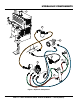


1. Hydraulic Motor — Bi-directional hydraulic motor that
is used in conjunction with the directional control valve
to operate the hydraulic dump cylinder and paddle
shaft.
2. Hydraulic Dump Cylinder — When activated, this
cylinder will cause the mixing drum to rotate to the
dump position. This cylinder is provided on mixers with
hydraulic dump capability.
3. Hydraulic Oil Sight Gauge — This gauge indicates
the level and temperature of the hydraulic oil. For
normal operation, oil level should be visible at the
midpoint on the sightglass.
4. — Directional hydraulic control valve.
Controls the direction of hydraulic fluid supplied to the
dump cylinder and paddle shaft.
5. Hydraulic Dump Lever — This lever is only provided
on mixers with hydraulic dump capability. Pull lever
outward to activate dump cylinder.
6. — 3-position lever.
Push inward for clockwise mixing rotation of blades.
Place in center position for no rotation (neutral/off).
7. Pump — Supplies hydraulic fluid to the hydraulic
control valve.
8. Hydraulic Oil Filter — 10 micron hydraulic filter. Filters
out small particles that are harmful to the hydraulic
system.
HYDRAULIC COMPONENTS