OPERATION MANUAL STX SERIES RIDE-ON POWER TROWEL © COPYRIGHT 2003, MULTIQUIP INC. STX55J6 MODEL # SERIAL # Revision #1(07/16/04) MULTIQUIP INC.. PARTS DEPARTMENT: 18910 WILMINGTON AVE. 800-427-1244 CARSON, CALIFORNIA 90746 FAX: 800-672-7877 SERVICE DEPARTMENT/TECHNICAL ASSISTANCE: 310-537-3700 800-421-1244 800-478-1244 FAX: 310-537-3927 FAX: 310-631-5032 E-mail:mq@multiquip.com • www.multiquip.
STX-SERIES — HERE'S HOW TO GET HELP HERE'S HOW TO GET HELP PLEASE HAVE THE MODEL AND SERIAL NUMBER ON-HAND WHEN CALLING PARTS DEPARTMENT 800-427-1244 or 310-537-3700 FAX: 800-672-7877 or 310-637-3284 SERVICE DEPARTMENT 800-421-1244 FAX: 310-537-4259 TECHNICAL ASSISTANCE 800-478-1244 FAX: 310-631-5032 WARRANTY DEPARTMENT 888-661-4279, or 310-661-4279 FAX: 310-537-1173 STX-SERIES • RIDE-ON POWER TROWEL — OPERATION MANUAL — REV.
STX-SERIES — TABLE OF CONTENTS Technical Assistance ............................................... 3 Table of Contents .................................................... 4 Training Checklist .................................................... 5 Daily Pre-Operation Checklist ................................. 6 Safety Message Alert Symbols ............................ 7-8 Rules For Safe Operation ....................................... 9 Operation And Safety Decals ................................
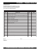
STX-SERIES — TRAINING CHECKLIST TRAINING CHECKLIST This checklist lists the minimum requirements for machine maintenance and operation. Please feel free to detach it and make copies. Use this checklist when training a new operator or use as a review for more experienced operators. TRAINING CHECKLIST NO. DESCRIPTION 1 Read Operator’s Manual completely. 2 Machine layout, location of components, checking of engine and hydraulic oil levels. 3 Fuel system, refueling procedure.
STX-SERIES — DAILY PRE-OPERATION CHECKLIST DAILY PRE-OPERATION CHECKLIST DAILY PRE-OPERATION CHECKLIST 1 Engine oil level. 2 Hydraulic oil level. 3 Radiator coolant level. 4 Condition of blades. 5 Blade pitch operation. 6 Safety Stop Switch operation. 7 Steering control operation. COMMENTS: PAGE 6 — STX-SERIES • RIDE-ON POWER TROWEL — OPERATION MANUAL — REV.
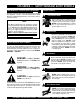
STX-SERIES — SAFETY MESSAGE ALERT SYMBOLS FOR YOUR SAFETY AND THE SAFETY OF OTHERS! HAZARD SYMBOLS Safety precautions should be followed at all times when operating this equipment. Failure to read and understand the Safety Messages and Operating Instructions could result in injury to yourself and others. NOTE This Owner's Manual has been developed to provide complete instructions for the safe and efficient operation of the MQ Whiteman STX-SERIES Ride-On Power Trowel.
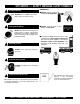
STX-SERIES — SAFETY MESSAGE ALERT SYMBOLS EMERGENCIES Accidental Starting ■ ALWAYS know the location of the nearest fire extinguisher. ALWAYS place the ON/OFF switch in the OFF position, and remove the key. ■ ALWAYS know the location of the nearest and first aid kit. Over Speed Conditions NEVER tamper with the factory settings of the engine governor or settings. Personal injury and damage to the engine or equipment can result if operating in speed ranges above maximum allowable.
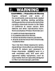
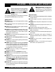
STX-SERIES — RULES FOR SAFE OPERATION CAUTION Failure to follow instructions in this manual may lead to serious injury or even death! This equipment is to be operated by trained and qualified personnel only! This equipment is for industrial use only and should not be regarded as a toy. ■ High Temperatures – Allow the machine and engine to cool before adding fuel or performing service and maintenance functions. Contact with hot components can cause serious burns.
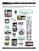
STX-SERIES — OPERATION AND SAFETY DECALS OPERATION AND SAFETY DECALS The STX-SERIES Ride-on Power Trowel is equipped with a number of operation and safety decals. These decals are provided for operator safety and maintenance information. Table 1 below illustrates these decals as they appear on the machine. Should any of these decals become unreadable, replacements can be obtained from your dealer. PAGE 10 — STX-SERIES • RIDE-ON POWER TROWEL — OPERATION MANUAL — REV.
STX-SERIES — SPECIFICATIONS Figure 1. STX-SERIES Dimension /Specifications Table 2. STX-Series Specifications STX55JDTCSL6 A–Length – in. (cm) 125 (318) B–Width – in. (cm) 65.0 (165) 56.0 (142) C–Height – in. (cm)1 Weight – lbs. (kgs.) Operating 2,000 (909) Weight – lbs. (kgs.) Shipping 2500 (1137) Sound Pressure – dBA2 97 2 2 3 Vibration – ft/s (m/ s ) <8.0 (2.5) Blade Tip Speed – FPM (m/s) 1924 (9.9) Engine – H.P.
STX-SERIES — GENERAL INFORMATION GENERAL INFORMATION Dual palm grip joystick controls located to the left and right of the operator are provided for steering the STX-SERIES Ride-on Power Trowel. The joysticks are linked to three hydraulic steering cylinders located within the frame of the machine. Detailed explanation of how the joystick controls affect the steering of the trowel can be found in Table 3, on page 18.
STX-SERIES — CONTROLS AND COMPONENTS Figure 2. STX-SERIES Controls and Components (Front) Figures 2 and 3 (pages 13 and 14) show the location of the controls, indicators and general maintenance parts. The function of each control, indicator or maintenance part is explained below: 1. 2. Seat – Place for operator to sit. Trowel blades will not rotate unless operator is seated. Seat is adjustable.
STX-SERIES — CONTROLS AND COMPONENTS Figure 3. STX-SERIES Controls and Components (Rear) 20. Documentation Box – Storage for documentation and other information regarding the trowel. 26. Blade Pitch Control Switch (left side) – Adjusts the left side blade pitch independently of the right side. 21. Battery – Provides +12V DC power to the electrical system. 27. Blade Pitch Control (Twin Pitch) – Adjusts the blade pitches simultaneously. 22.
STX-SERIES — PRE-INSPECTION PRE-INSPECTION The following sections are intended to assist the operator with preNOTE inspection and the initial start-up of the STX-SERIES Ride-On Power Trowel. It is extremely important that these sections are read carefully before attempting to use the trowel in the field. DO NOT use your Ride-On Power Trowel until these sections are thoroughly understood. (FILL TO OVERFLOW WITH HYDRAULIC SYSTEM COOL) Figure 5.
STX-SERIES — INITIAL START-UP CAUTION INITIAL START-UP NEVER disable or disconnect the Safety Stop Switch. It is provided for the operators’ safety and injury may result if it is disabled, disconnected or improperly maintained. CAUTION NEVER operate the trowel in a confined area or enclosed area structure that does not provide ample free flow of air. 3. ALWAYS wear approved eye and hearing protection before operating the ride-on power trowel. 4.
STX-SERIES — INITIAL START-UP 6. Turn the ignition key clockwise to the (start) position. The oil and charge indicator lights (Figure 9) should be on. Figure 9. Oil and Charge Indicator Lights NOTE In cold weather turn and hold the ignition key counter clockwise to the preheat position, wait until the preheat indicator goes off before turning the ignition key clockwise to the start position. Two or three preheat cycles may be necessary in very cold weather. 7.
STX-SERIES — OPERATION OPERATION The following section is intended as a basic guide to the Ride-On Power NOTE Trowel operation, and is not to be considered a complete guide to concrete finishing. It is strongly suggested that all operators (experienced and novice) read “Slabs on Grade” published by the American Concrete Institute, Detroit Michigan.
STX-SERIES — OPERATION 1. The foot pedal (Figure 13) solely controls blade speed. The position of the foot pedal determines the blade speed. Slow blade speed is obtained by slightly depressing the pedal. Maximum blade speed is obtained by fully depressing the pedal. 5. Practice maneuvering the Ride-on Power Trowel using the information listed in Table 3. Try to practice controlled motions as if you were finishing a slab of concrete. Practice edging and covering a large area 6.
STX-SERIES — OPERATION Blade Pitch Control Engine Shut-Down The trowel blades can be pitched for various finishing operations with the two rocker switches located on the left control panel next to the left joystick control (Figure 17). 1. Return the speed control lever (Figure 19) to low idle, and allow the engine to idle for 5 minutes . HIG H LO W Figure 19. Blade Pitch Control Figure 17.
STX-SERIES — MAINTENANCE MAINTENANCE MAINTENANCE PROCEDURES See the engine manual supplied with your machine for appropriate engine maintenance schedule and troubleshooting guide for problems. NOTE At the front of the book (Page 6) there is a “Daily Pre-Operation Checklist”. Make copies of this checklist and use it on a daily basis. CAUTION Disconnect battery cables before attempting any service or maintenance on the Ride-on Power Trowel. ALWAYS allow the engine to cool before servicing.
STX-SERIES — MAINTENANCE Matching Blade Pitch for Both Sets of Blades This rod is basically a turnbuckle (Figure 22). Rotating it in one direction increases the length and corresponding trowel speed. Rotating it the opposite direction decreases the length and trowel speed. The right side trowel speed should be within 3 rpm of the left. Sometimes it may be necessary to match blade pitch between the left and right sets of blades. There are some signs that this may be necessary.
STX-SERIES — MAINTENANCE Adjustments are made by tightening or loosening the blade pitch adjustment bolt (Figure 24). Figure 24. Blade Pitch Adjustment Bolt Changing A Blade It is recommended that all the blades on the entire machine are changed at the same time. If only one or some of the blades are changed at one time, the machine will not finish concrete consistently and the machine may wobble or bounce. 1. Place the machine on a flat, level surface.
STX-SERIES — MAINTENANCE Once the pressure gauges are installed and the spiders chained together, the system can be checked. Checking Hydraulic Pressure Many hydraulic problems are a result of low fluid levels. Before checking any other possibilities, make sure the hydraulic fluid level is up to the top of the sight glass which is located at the back/center of the frame. With the foot pedal in the idle position and the engine at full speed, the pressure should be 200 to 300 psi.
STX-SERIES — MAINTENANCE Checking Steering Pressure Steering pressure is also checked at either of the high pressure diagnostic couplers under the right grill guard. Check steering pressure at either coupler with a 300-600 PSI gauge. (Table 4) indicates proper steering pressure. Check with engine at Full Speed. Table 4.
STX-SERIES — MAINTENANCE Pitch Pressure Check Pitch Pressure Adjustment Access the pitch block and pitch pressure test port at the rightrear of the trowel (Figure 29). Removal of the right-rear seat frame panel may be necessary. Pitch pressure must be measured with a pitch switch activated. With pitch switches unactivated, the pitch pressure will be the same as the charge/steering pressure. Proper pitch pressure is 2300 PSI. If the pitch pressure check is out of specification, check the following: 1.
STX-SERIES — TROUBLESHOOTING TABLE 5. TROUBLESHOOTING SYMPTOM POSSIBLE PROBLEM Fuel? Look at the fuel system. Make sure there is fuel being supplied to the engine. Check to ensure that the fuel filter is not clogged. Ignition? Check to ensure that the ignition switch has power and is functioning correctly. Other problems? Consult engine manufacturer’s manual. Loose wire connections? Check wiring. Replace as necessary. Bad contacts? Replace seat cushion (contains the switch).
STX-SERIES — TROUBLESHOOTING TABLE 5. TROUBLESHOOTING (CONTINUED) SYMPTOM POSSIBLE PROBLEM SOLUTION Wiring? Check all electrical connections, including the master on/off switch and check to see if wiring is in good condition with no shor ts. Replace as necessary. Lights? Check to see if light bulbs are still good. Replace if broken. Retardant? Check the tank to make sure retardant is present. Fill tank as necessary.
NOTE PAGE STX-SERIES • RIDE-ON POWER TROWEL — OPERATION MANUAL — REV.
OPERATION MANUAL HERE'S HOW TO GET HELP PLEASE HAVE THE MODEL AND SERIAL NUMBER ON-HAND WHEN CALLING PARTS DEPARTMENT 800-427-1244 or 310-537-3700 FAX: 800-672-7877 or 310-637-3284 SERVICE DEPARTMENT 800-421-1244 FAX: 310-537-4259 TECHNICAL ASSISTANCE 800-478-1244 FAX: 310-631-5032 WARRANTY DEPARTMENT 888-661-4279, or 310-661-4279 FAX: 310-537-1173 MULTIQUIP INC. POST OFFICE BOX 6254 CARSON, CA 90749 310-537-3700 • 800-421-1244 FAX: 310-537-3927 E-MAIL: mq@multiquip.com WWW. multiquip.