PARTS AND OPERATION MANUAL MQ POWER WHISPERWELDTM DC WELDER/AC GENERATOR © COPYRIGHT 2001, MULTIQUIP INC. Model SGW-250SS Parts No. D2845200004A Revision #2 (08/08/01) MULTIQUIP INC. PARTS DEPARTMENT: 18910 WILMINGTON AVE. 800-427-1244 CARSON, CALIFORNIA 90746 FAX: 800-672-7877 310-537-3700 SERVICE DEPARTMENT: 800-421-1244 800-478-1244 FAX: 310-537-3927 FAX: 310-537-4259 E-mail:mq@multiquip.com • www:multiquip.
PAGE 2 — SGW-250SS DC WELDER/AC GENERATOR— PARTS & OPERATION MANUAL — REV.
HERE'S HOW TO GET HELP PLEASE HAVE THE MODEL AND SERIAL NUMBER ON-HAND WHEN CALLING PAR TS DEP AR TMENT ARTS DEPAR ARTMENT 800/427-1244 or 310/537-3700 FAX: 800/672-7877 or 310/637-3284 SER VICE DEP AR TMENT DEPAR ARTMENT SERVICE 800/835-2551 or 310/537-3700 FAX: 310/638-8046 WARRANTY DEP AR TMENT DEPAR ARTMENT 800/835-2551 or 310/537-3700 FAX: 310/638-8046 MAIN 800/421-1244 or 310/537-3700 FAX: 310/537-3927 SGW-250SS DC WELDER/AC GENERATOR — PARTS & OPERATION MANUAL — REV.
TABLE OF CONTENTS Here's How To Get Help ............................................ 3 Table Of Contents ..................................................... 4 Parts Ordering Procedures ....................................... 5 Rules For Safe Operation ...................................... 6-7 Operation and Safety Decals ................................. 8-9 Specifications .......................................................... 10 General Information ................................................
PARTS ORDERING PROCEDURES ■ ■ ■ ■ ■ ■ ■ Dealer account number Dealer name and address Shipping address (if different than billing address) Return fax number Applicable model number Quantity, part number and description of each part Specify preferred method of shipment: • • • • UPS Ground UPS Second Day or Third Day* UPS Next Day* Federal Express Priority One (please provide us with your Federal Express account number)* • • Airborne Express* Truck or parcel post *Normally shipped the same day the order
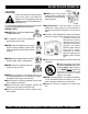
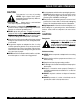
RULES FOR SAFE OPERATION CAUTION: Failure to follow instructions in this manual may lead to serious injury or even death! This equipment is to be operated by trained and qualified personnel only! This equipment is for industrial use only. The following safety guidelines should always be used when operating the SGW-250SS Welder/AC Generator : GENERAL SAFETY ■ DO NOT operate or service this equipment before reading this entire manual. ■ This equipment should not be operated by persons under 18 years of age.
RULES FOR SAFE OPERATION CAUTION: This generator is a source of providing LETHAL high voltages. Never permit unqualified personnel-especially children to operate the generator. ■ Always refuel in a well-ventilated area, away from sparks and open flames. ■ This generator is equipped with a ground terminal for your protection. Always complete the grounding path from the generator to an external grounding source.
OPERATION AND SAFETY DECALS PAGE 8 — SGW-250SS DC WELDER/AC GENERATOR— PARTS & OPERATION MANUAL — REV.
OPERATION AND SAFETY DECALS P/N DCL160 SGW-250SS DC WELDER/AC GENERATOR — PARTS & OPERATION MANUAL — REV.
SGW-250SS — SPECIFICATIONS Table 1. Specifications Welder Specifications Rated Output (CV/CC) 4.0/5.6 kW Rated Current (CC) 200 Amps Rated Voltage (CV/CC) 20/28 Volts Duty Cycle 100% Rated Speed 3600/rpm Voltage Range 15-28 Volts Current Range 50 - 225 Amps Generator Specifications Phase Single Phase Wires 3-Wires (Neutral Grounded) Rated Output 7.2 kW Rated Voltage 120/240 Volts Frequency 60 Hz Power Factor 1.
SGW-250SS — GENERAL INFORMATION SGW-250SS FAMILIARIZATION Generator The MQ Power Model SGW-250SS welder/generator can provide 200 amps of welding current when in the CV/DC mode and 250 amps of welding current when in the CC/DC mode. When used as a generator it can provide a maximum of 7,200 watts of power.
SGW-250SS — DIMENSIONS Figure 1. SGW-250SS Dimensions PAGE 12 — SGW-250SS DC WELDER/AC GENERATOR— PARTS & OPERATION MANUAL — REV.
SGW-250SS — TRAILER-SAFETY GUIDELINES Frame Length - This measurement is from the ball hitch to the rear bumper (reflector). ALWAYS make sure the trailer is in good 5. Frame Width - This measurement is from fender to operating condition. Check the tires for fender. proper inflation and wear. Also check the 6. Jack Stand - Trailer support device with maximum wheel lug nuts for proper tightness. pound requirement from the tongue of the trailer. 7. Coupler - Type of hitch used on the trailer for towing.
SGW-250SS — TRAILER-SPECIFICATIONS Table 1. Specifications MODEL APPLICATION FU E L C E LL BRAKE SYSTEM GVWR FRAME LENGTH FRAME WIDTH JACK STAND TRLR-10W SDW225, SGW250,TLW300 NO NO 1900LB S 96" 50" 800LB . FULL TILT WHEEL TRLR-10 DCA10, TLG12, DCA-15 NO NO 1900LB S 96" 50" 800LB . FULL TILT WHEEL TRLR-10XF DCA10, TLG-12, DCA15, TLW-300 52 GAL NO 1900LB S 96" 50" 800LB . FULL TILT WHEEL TRLR-225W WELDERS, D A 7000S S NO NO 2200LB S 85" 42" 800LB .
SGW-250SS — TRAILER-SPECIFICATIONS Table 1. Specifications (Con't) MODEL COUPLER TIRES WHEELS AXLE HUBS SUSPENSION ELECTRICAL TRLR-10W 2" B A LL C LA S S 2 ADJUSTABLE 175-13C 13"X4.50" 2200# 2X 2 5 LUG 3 LE A F 4 WIRE LOOM W/ 4 POLE FLAT TRLR-10 2" B A LL C LA S S 2 ADJUSTABLE 175-13C 13"X4.5" 2200#2X 2 5 LUG 3 LE A F 4 POLE FLAT TRLR-10XF 2" B A LL C LA S S 2 ADJUSTABLE 175-13C 13"X4.5" 2200#2X 2 5 LUG 3 LE A F 4 POLE FLAT 2" B A LL C LA S S 2 ADJUSTABLE 175-13B 13X4.
SGW-250SS —TRAILER SAFETY GUIDELINES Tires/Wheels/Lug Nuts Tires and wheels are a very important and critical components of the trailer. When specifying or replacing the trailer wheels it is important the wheels, tires, and axle are properly matched. CAUTION: DO NOT attempt to repair or modify a wheel. DO NOT install in inner tube to correct a leak through the rim.
SGW-250SS —TRAILER SAFETY GUIDELINES Table 4. Suspension Torque Requirements Item Torque (Ft.-Lbs.) 3/8" U-BOLT MIN-30 MAX-35 7/16" U-BOLT MIN-45 MAX-60 1/2" U-BOLT MIN-45 MAX-60 SHACKLE BOLT SNUG FIT ONLY. PARTS MUST ROTATE FREELY. SPRING EYE BOLT LOCKING NUTS OR COTTER PINS ARE PROVIDED TO RETAIN NUT-BOLT ASSEMBLY. MIN-30 MAX-50 SHOULDER TYPE SHACKLE BOLT Lug Nut Torque Requirements It is extremely important to apply and maintain proper wheel mounting torque on the trailer.
SGW-250SS —TRAILER-WIRING DIAGRAM PAGE 18 — SGW-250SS DC WELDER/AC GENERATOR— PARTS & OPERATION MANUAL — REV.
SGW-250SS —TOWING ■ ALWAYS attach trailer's safety chain to bumper of towing vehicle. Towing Safety Precautions CAUTION : Check with your county or state safety towing regulations department before towing your generator. Vehicle towing codes and regulations can vary from state to state.
SGW-250SS — CONTROLS AND INDICATORS Figures 5 and 6 show the location of the controls and indicators. The functions of each control or indicator is described below and on the preceding page. 8. Engine Air Cleaner – Prevents dirt and other debris from entering the fuel system. Lift locking latch on air filter cannister to gain access to filter element. 1. Welding Type (Wire/Stick) Selector Switch (CV/CC) – Turn this selector switch to either the CV or CC for welding. DO NOT turn this switch under load.
SGW-250SS — CONTROLS AND INDICATORS 16. Positive Welding Output Terminal – Connect the welding cable to this terminal. Select the appropriate polarities according to the application. See Table 7. 23. Frame Ground Lug – Connect a ground strap between this lug and a ground rod. Make sure the ground rod is inserted deep into the ground to provide a good earth ground. Consult with local Electrical and Safety Codes for proper connection. 17.
SGW-250SS — INSTALLATION Outdoor Installation Indoor Installation Install the welder/generator in a location where it will not be exposed to rain or sunshine. Make sure the welder/generator is on secure level ground so that it cannot slide or shift around. Install the generator in a manner so the exhaust fumes will not be discharged in the direction of nearby homes. Exhaust gases from gasoline engines are extremely poisonous.
SGW-250SS — PRE-SETUP General Inspection Prior to Operation The SGW-250SS utilizes a generator that has been thoroughly inspected and accepted prior to shipment from the factory. However, be sure to check for damaged parts or components, or loose nuts and bolts, which could have occurred in transit. Ground The nut and ground terminal on the generator should always be used to connect the generator to a suitable ground. The ground path should be of #8 size wire.
SGW-250SS — PRE-SETUP Lubrication Oil Fill the engine crankcase with lubricating oil through the filler hole, but do not overfill. Make sure the welder/generator is level. With the dipstick inserted all the way, but without being screw into the filler hole, verify that the oil level is maintained between the two notches (Figure 7) on the dipstick. See Table 4 for proper selection of engine oil. Fuel Fill the fuel tank with clean and fresh unleaded gasoline. DO NOT fill the tank beyond capacity.
BLW-400SSW — PRE-SETUP CAUTION : When adding coolant or antifreeze to the radiator, do not remove the radiator cap until the unit has completely cooled. Day-to-day addition of coolant or antifreeze is done from the reserve tank. See Table 9 for engine, radiator and reserve tank coolant capacities. Make sure the coolant level in the reserve tank is always between the "H" and the "L" markings. Cleaning the Radiator The radiator may overheat if the fins become overloaded with dust or debris.
SGW-250SS — INSTRUMENTATION CAUTION : Idle Control Switch When using a combination of dual receptacles, total load should not exceed the rated capacity of the generating set. Power Outlets The generator has the following 60 Hz, 120/240 volt singlephase receptacles.
SGW-250SS — LOAD APPLICATION CAUTION: Single Phase Load Motors and motor-driven equipment draw much greater current for starting than during operation. Always be sure to check the nameplate on the generator and equipment to insure the wattage, amperage and frequency requirements are satisfactorily supplied by the generator for operating the equipment. Generally, the wattage listed on the nameplate of the equipment is its rated output.
SGW-250SS — WELDER OPERATING INSTRUCTIONS Welding Cables and Polarities Connect the welding cables (Figure 8) to the welder's output terminals located on the control panel. The output terminals have positive(+) and negative(-) polarities. Select the appropriate polarities according to the application (SeeWelding Application, Table 6). NOTE Attach terminal connectors at the end of each cable. NEVER connect exposed wires (Figure 9) directly to the terminal.
SGW-250SS — WELDER OPERATING INSTRUCTIONS CAUTION : NEVER switch the CV/CC Selector Switch during any welding operation. When switching a selector switch, fully rotate it to the right or left position. 1. Turn the CV/CC Selector Switch (Figure 10) to the CV position, and adjust voltage using the Voltage Control knob. NOTE When the CV/CC Selector Switch is in the CC position, the Voltage Control function is inoperative. 3. Set the CC Current Range Selector Switch to the desired position (Low/High). 4.
SGW-250SS — WELDER OPERATING INSTRUCTIONS Welding and Auxiliary Outputs. Duty Cycle The welding and auxiliary outputs can be used simultaneously, subject to all of the following conditions: The welder is rated at 100% duty cycle at 250 amps. However the duty cycle depends upon the welding current. Select the appropriate duty cycle from Table 7 to prevent overload. z CC/CV Selector Switch is in the CC mode. z CC Current Range Selector is in the low mode. z Current Control is in the MAX position.
SGW-250SS — ENGINE OPERATING INSTRUCTIONS WARNING: CAUTION: The engine's exhaust contains harmful W AY S ventilate the emissions. A LLW exhaust when operating inside tunnels, excavations or buildings. Direct exhaust away from nearby personnel. AR T ” push-button STAR ART NEVER press the the “ST switch while the engine is running. Before Starting 1. Be sure to disconnect the electrical load and switch the main circuit breaker to the “OFF” position prior to starting the engine. 6.
SGW-250SS — MAINTENANCE General Inspection At least daily or prior to each use, the welder/AC generator should be cleaned and inspected for deficiencies. Check for loose, missing or damaged nuts, bolts or other fasteners. Also check for fuel or oil leaks. Engine Side: For a more detail engine maintenance schedule refer to the HOND A Engine Oper ator's Man ual. HONDA Operator's Manual Air Cleaner: Every 50 hours: Remove air cleaner element by removing the wing bolts and screws.
SDW-225SS — MAINTENANCE SGW-250SS — MAINTENANCE INSPECTION / MAINTENANCE ENGINE GENERATOR 10 Hrs DAILY Check Engine Fluid Levels X Check Air Cleaner X Check Battery Acid Level X Check Fan Belt Condition X Check for Leaks X Check for Loosening of Parts X 250 Hrs Replace Engine Oil and Filter *1 X Clean Air Filter X Drain Bottom of Fuel Tank X Clean Unit, Inside and Outside X 500 Hrs Change Fuel Filter *2 X Clean Radiator and Check Coolant Protection Level X 1000 Hrs Replace Ai
SGW-250SS — PREPARATION FOR LONG -TERM STORAGE Welder/Generator Storage For storage of the generating set for over 30 days, the following is required: z Drain the fuel tank completely. z Run the engine until the gasoline in the carburetor is completely consumed. z Completely drain the oil from the crankcase and refill with fresh oil. z Remove the spark plug, pour 2 or 3 cc of SAE 30 oil into the cylinder and crank slowly to distribute the oil.
SGW-250SS —ENGINE/GENERATOR WIRING DIAGRAM SGW-250SS DC WELDER/AC GENERATOR — PARTS & OPERATION MANUAL — REV.
SGW-250SS — TROUBLESHOOTING (WELDER) Practically all breakdowns can be prevented by proper handling and maintenance inspections, but in the event of a breakdown, please take a remedial action following the diagnosis based on the Welder Troubleshooting (Table 8) information shown below. If the problem cannot be remedied, please consult our company's business office or service plant. TABLE 14. WELDER TROUBLESHOOTING SYMPTOM AC voltage is not present in generator's AC section or welding section.
SGW-250SS — TROUBLESHOOTING (ENGINE) Practically all breakdowns can be prevented by proper handling and maintenance inspections, but in the event of a breakdown, please take a remedial action following the diagnosis based on the Engine Troubleshooting (Table 9) shown below. If the problem cannot be remedied, please consult our company's business office or service plant. TABLE 15. ENGINE TROUBLESHOOTING (PART 1) SYMPTOM Engine does not start. POSSIBLE PROBLEM SOLUTION No fuel? Replenish fuel.
SGW-250SS — TROUBLESHOOTING (ENGINE) TABLE 15. ENGINE TROUBLESHOOTING (PART 2) SYMPTOM Engine revolution is not smooth. POSSIBLE PROBLEM Fuel filter clogged or dirty? Clean or change. Air cleaner clogged? Clean or change. Fuel leak due to loose injection pipe retaining nut? Tighten nut. Injection pump malfunctioning? Repair or replace. Incorrect nozzle opening pressure? Adjust. Injection nozzle stuck or clogged? Repair or replace. Fuel over flow pipe clogged? Clean.
SGW-250SS — TROUBLESHOOTING (ENGINE) TABLE 15. ENGINE TROUBLESHOOTING (PART 3) SYMPTOM Engine fails to start and starter rotates. Engine starts and remains at low speed. Starter does not run. POSSIBLE PROBLEM SOLUTION Broken pre-heat circuit? Check pre-heat circuit. No fuel? Add fuel. Defective wiring? Check wiring. Clogged fuel strainer? Clean or replace. Clogged air cleaner? Clean or replace. Disconnected wiring? Check and repair wiring. Battery discharged? Charge battery.
EXPLANATION OF CODE IN REMARKS COLUMN How to read the marks and remarks used in this parts book. Items Found In the “Remarks” Column Serial Numbers-Where indicated, this indicates a serial number range (inclusive) where a particular part is used. Model Number-Where indicated, this shows that the corresponding part is utilized only with this specific model number or model number variant.
SGW-250SS — SUGGESTED SPARE PARTS SGW W/HOND A GX610 AIR-COOLED ENGINE 1 TO 3 UNITS W/HONDA Qty. P/N Description 5 ......... 17010ZJ1000 ... AIR FILTER 1 ......... 17218ZJ1000 ... AIR FILTER, OUTER 5 ......... 16910ZE8015 .. FUEL FILTER 5 ......... 15400PR3004 .. OIL FILTER 1 ......... 15427ZJ1000 ... SCREEN, CRANKCASE OIL FILTER 1 ......... 35480ZJ1812 ... SWITCH ASSY., OIL LEVEL 1 ......... 0601200102 ..... STARTER SWITCH 1 ......... 0810105800 ..... FUEL CAP 1 ......... 0601805331 .....
SGW-250SS — GENERATOR ASSY. GENERATOR ASSY. PAGE 42 — SGW-250SS DC WELDER/AC GENERATOR— PARTS & OPERATION MANUAL — REV.
SGW-250SS — GENERATOR ASSY. GENERATOR ASSY.
SGW-250SS — CONTROL PANEL ASSY. CONTROL PANEL ASSY. PAGE 44 — SGW-250SS DC WELDER/AC GENERATOR— PARTS & OPERATION MANUAL — REV.
SGW-250SS — CONTROL PANEL ASSY. CONTROL PANEL ASSY.
SGW-250SS — CONTROL PANEL ASSY. CONTROL PANEL ASSY. PAGE 46 — SGW-250SS DC WELDER/AC GENERATOR— PARTS & OPERATION MANUAL — REV.
SGW-250SS — CONTROL PANEL ASSY. CONTROL PANEL ASSY. NO 41 42 43 44 45 46 47 48 49 50 51 52 53 54 55 PART NO 0601804211 0027104012 0601823204 0027103020 0601827399 0027105012 0601823707 0027105020 0601815870 D9522001204 0601815758 D9522000804 0027105020 8511864601A 0016906016 0601802137 0601803117 PART NAME QTY. REMARKS CURRENT TRANSFORMER ............................. 3 ........... MCT-100Y MACHINE SCREW 6 RECTIFIER ....................................................... 2 ...........
SGW-250SS — ELECTRIC PARTS ASSY. ELECTRIC PARTS ASSY. PAGE 48 — SGW-250SS DC WELDER/AC GENERATOR— PARTS & OPERATION MANUAL — REV.
SGW-250SS — ELECTRIC PARTS ASSY. ELECTRIC PARTS ASSY. NO 1 2 2-1 * 3 4 5 6 7 8 9 10 11 12 13 14 15 PART NO D2263500303 D2263500403 0601831054 0017106016 1622636103Z 1992636004 0050403020 0010106025 0030006000 A6356600404 0017105010 D2356200003 0207006000 0010106040 0038706000 0016906016 A6356400303B 0017105010 PART NAME QTY. REMARKS AC REACTOR 2 DC REACTOR ..................... 1 ............... INCLUDES ITEMS W/ * THERMOSTAT ..................... 1 ...............
SGW-250SS — BATTERY ASSY. BATTERY ASSY. PAGE 50 — SGW-250SS DC WELDER/AC GENERATOR— PARTS & OPERATION MANUAL — REV.
SGW-250SS — BATTERY ASSY. BATTERY ASSY. NO 1 2 3 4 5 6 7 8 PART NO 0805081004 D2345200004 0805082704 0037806000 0040006000 0041206000 0602220600 0602220601 D1343200604 PART NAME QTY. REMARKS BATTERY SHEET.................. 1 ............ REPLACES 1702202104 BATTERY BAND 1 BATTERY BOLT 2 WING NUT 2 LOCK WASHER 2 PLAIN WASHER 2 TERMINAL CAP RED 1 TERMINAL CAP BLACK 1 TERMINAL CAP 1 SGW-250SS DC WELDER/AC GENERATOR — PARTS & OPERATION MANUAL — REV.
SGW-250SS — TAIL PIPE ASSY. TAIL PIPE ASSY. PAGE 52 — SGW-250SS DC WELDER/AC GENERATOR— PARTS & OPERATION MANUAL — REV.
SGW-250SS — TAIL PIPE ASSY. TAIL PIPE ASSY. NO 1 2 3 PART NO D2335100013 D9102200104 0016908030 PART NAME OUTLET PIPE PIPE BAND HEX HEAD BOLT QTY. 1 1 1 REMARKS SGW-250SS DC WELDER/AC GENERATOR — PARTS & OPERATION MANUAL — REV.
SGW-250SS — FUEL TANK ASSY. FUEL TANK ASSY. PAGE 54 — SGW-250SS DC WELDER/AC GENERATOR— PARTS & OPERATION MANUAL — REV.
SGW-250SS — FUEL TANK ASSY. FUEL TANK ASSY. NO 1 1-1 * 1-2 * 2 3 4 5 6 7 8 PART NO A6365000402B 0810105900 0810105900 3015530004 0150200011 0602125032 0016908020 0605513143 0605515093 0605515240 PART NAME QTY. REMARKS FUEL TANK ................................ 1 ......... INCLUDES ITEMS W/ * CAP FUEL TANK ....................... 1 .........
SGW-250SS — ENCLOSURE ASSY. ENCLOSURE ASSY. PAGE 56 — SGW-250SS DC WELDER/AC GENERATOR— PARTS & OPERATION MANUAL — REV.
SGW-250SS — ENCLOSURE ASSY. ENCLOSURE ASSY.
SGW-250SS — NAME PLATE AND DECALS ASSY. NAME PLATE AND DECALS ASSY. PAGE 58 — SGW-250SS DC WELDER/AC GENERATOR— PARTS & OPERATION MANUAL — REV.
SGW-250SS — NAME PLATE AND DECALS ASSY. NAME PLATE AND DECALS ASSY. NO PART NO PART NAME QTY. REMARKS 1* D2552000404 DECAL: OPERATING INSTRUCTIONS ............ 1 .......... REPLACES D25200040B 2* D9512100203 DECAL: CAUTION (MULTIPLE) ........................ 1 .......... REPLACES 91210020 3* 0820610404 DECAL: WARNING (TRANSFER SWITCH) 1 4* 0820610304 DECAL: READ OWNER’S MANUAL ................. 1 .......... DCS01 5* 8700611904 DECAL: DANGER ELECT. SHOCK HAZARD ... 1 ..........
HONDA GX610VXD ENGINE — CYLINDER HEAD ASSY. CYLINDER HEAD ASSY. PAGE 60 — SGW-250SS DC WELDER/AC GENERATOR— PARTS & OPERATION MANUAL — REV.
HONDA GX610VXD ENGINE — CYLINDER HEAD ASSY. CYLINDER HEAD ASSY. NO 1 2 3 * 4 * 5 6 7 8 9 10 11 12 13 14 15 16 17 18 19 20 21 PART NO 12210ZJ1000 12220ZJ1U80 12205ZE2305 12216ZE2300 12251ZJ1003 12311ZJ1000 12314ZJ1000 12391ZJ1000 15611921000 17101ZJ1000 17151ZJ1003 90121ZJ1000 91301805000 92900080250B 9430112200 9405008000 9430112200 957010603200 957011007500 957011013000 9807952876 PART NAME QTY. REMARKS CYLINDER HEAD COMP., R. ....... 1 .... INCLUDES ITEMS W/ * CYLINDER HEAD COMP., L. ....... 1 ....
HONDA GX610VXD ENGINE — CYLINDER BARREL ASSY. CYLINDER BARREL ASSY. PAGE 62 — SGW-250SS DC WELDER/AC GENERATOR— PARTS & OPERATION MANUAL — REV.
HONDA GX610VXD ENGINE — CYLINDER BARREL ASSY. CYLINDER BARREL ASSY. NO 1 2 3 4 5 * 7 10 11 12 15 16 17 18 20 * 22 23 24 25 26 27 1 PART NO 12000ZJ1810 12356ZJ1000 12358ZJ1000 12372ZE2300 13321ZJ1000 13322ZJ1000 13323ZJ1000 15400PT7005 25523VD6010 31511ZJ1000 35480ZJ1812 90014ZE6000 90018PN3000 90029888000 90031ZE1000 91201ZJ1003 91353671003 9280014000 9405010000 9410914000 957010607509 961406003010 120A0ZJ1000 PART NAME QTY. REMARKS CYLINDER BARREL ASSY. .............. 1...............
HONDA GX610VXD ENGINE — CRANKCASE COVER ASSY. CRANKCASE COVER ASSY. PAGE 64 — SGW-250SS DC WELDER/AC GENERATOR— PARTS & OPERATION MANUAL — REV.
HONDA GX610VXD ENGINE — CRANKCASE COVER ASSY. CRANKCASE COVER ASSY. NO 1 2 3 4* 5 6 7 8 9 10 11 12 16* 17* 18 19 20 21 22 23 24 PART NO 11300ZJ1000 11381ZJ1000 12105ZAO701 13321ZJ1000 13322ZJ1000 13323ZJ1000 15120ZJ1000 15124ZJ1003 15232ZJ1000 15348ZJ1000 15427ZJ1000 15655ZJ1000 16541ZJ1000 16542ZJ1000 91201ZJ1003 91259NM0000 91302MB6830 93500050100A 9430108140 957010602000 957010805000 9621112000 966000601600 PART NAME QTY. REMARKS COVER ASSY., CRANKCASE ..... 1 .........
HONDA GX610VXD ENGINE — CRANKSHAFT ASSY. CRANKSHAFT ASSY. PAGE 66 — SGW-250SS DC WELDER/AC GENERATOR— PARTS & OPERATION MANUAL — REV.
HONDA GX610VXD ENGINE — CRANKSHAFT ASSY. CRANKSHAFT ASSY. NO 3 4 PART NO 13310ZJ0880 90401ZJ1000 PART NAME QTY. CRANKSHAFT COMP. V-TYPE 1 WASHER, CRANKSHAFT THRUST 1 REMARKS SGW-250SS DC WELDER/AC GENERATOR — PARTS & OPERATION MANUAL — REV.
HONDA GX610VXD ENGINE — PISTON ASSY. PISTON ASSY. PAGE 68 — SGW-250SS DC WELDER/AC GENERATOR— PARTS & OPERATION MANUAL — REV.
HONDA GX610VXD ENGINE — PISTON ASSY. PISTON ASSY. NO 1 3 4 5 6 * 7 * 8 PART NO 13010ZE8601 13011ZE8601 13011ZE8602 13012ZE8601 13013ZE8601 13101ZJ1000 13102ZJ1000 13103ZJ1000 13104ZJ1000 13111ZJ1000 13210ZJ1000 13211ZJ1003 13212ZJ1003 13213ZJ1003 13214ZJ1003 13215ZJ1003 13216ZJ1003 13217ZJ1003 13213ML0000 13215KM3000 9460118000 PART NAME QTY. REMARKS RING SET, PISTON (STD) NIPPON 2 RING SET, PISTON (0.25) NIPPON 2 RING SET, PISTON (0.25) TEIKOKU 2 RING SET, PISTON (0.50) NIPPON 2 RING SET, PISTON (0.
HONDA GX610VXD ENGINE — CAMSHAFT ASSY. CAMSHAFT ASSY. PAGE 70 — SGW-250SS DC WELDER/AC GENERATOR— PARTS & OPERATION MANUAL — REV.
HONDA GX610VXD ENGINE — CAMSHAFT ASSY. CAMSHAFT ASSY.
HONDA GX610VXD ENGINE — FAN COVER ASSY. FAN COVER ASSY. PAGE 72 — SGW-250SS DC WELDER/AC GENERATOR— PARTS & OPERATION MANUAL — REV.
HONDA GX610VXD ENGINE —FAN COVER ASSY. FAN COVER ASSY.
HONDA GX610VXD ENGINE — CARBURETOR ASSY. CARBURETOR ASSY. PAGE 74 — SGW-250SS DC WELDER/AC GENERATOR— PARTS & OPERATION MANUAL — REV.
HONDA GX610VXD ENGINE — CARBURETOR ASSY. CARBURETOR ASSY.
HONDA GX610VXD ENGINE — AIR CLEANER ASSY. AIR CLEANER ASSY. PAGE 76 — SGW-250SS DC WELDER/AC GENERATOR— PARTS & OPERATION MANUAL — REV.
HONDA GX610VXD ENGINE — AIR CLEANER ASSY. AIR CLEANER ASSY. NO 1 2 * 3 * 4 5 6 7 8 9 10 11 12 13 14# 15& 16 17 PART NO 17010ZJ1000 17216ZJ1000 17217ZJ1000 17218ZJ1000 17220ZJ1000 17231ZJ1000 17232ZJ1000 17237ZJ1000 17251ZJ1000 17255758000 17257HB3000 90017ZJ1000 90018ZE1000 90120102000 93500040200A 938910501608 957010601800 PART NAME QTY. REMARKS ELEMENT SET, AIR CLEANER ............. 1 ......... INCLUDES ITEMS W/ * GASKET A, ELEMENT 1 GASKET B, ELEMENT 1 FILTER (OUTER) 1 HOUSING COMP., AIR CLEANER ......
HONDA GX610VXD ENGINE — MUFFLER ASSY. MUFFLER ASSY. PAGE 78 — SGW-250SS DC WELDER/AC GENERATOR— PARTS & OPERATION MANUAL — REV.
HONDA GX610VXD ENGINE — MUFFLER ASSY. MUFFLER ASSY. NO 1 2* 3* 4* 5* 6* 7* 8* 9* PART NO 06183ZJ1820 18310ZJ1000 18321ZJ1000 18330ZJ1601 18333ZJ1000 18396ZJ1003 957010801400 957010802000 957010600800 PART NAME QTY. REMARKS MUFFLER KIT HIGH B ................. 1 ........ INCLUDES ITEMS W/* MUFFLER COMP. HIGH .............. 1 ........ 18310ZJ1003 PROTECTOR,MUFFLER HIGH .... 1 ........ 18321ZJ1003 PIPE COMP., EX. HIGH-L 1 STAY, MUFFLER HIGH ................. 1 ........ 18338ZJ1003 BAND ASSY.
HONDA GX610VXD ENGINE — FUEL PUMP ASSY. FUEL PUMP ASSY. PAGE 80 — SGW-250SS DC WELDER/AC GENERATOR— PARTS & OPERATION MANUAL — REV.
HONDA GX610VXD ENGINE — FUEL PUMP ASSY. FUEL PUMP ASSY. NO 1 2 4 5 6 7 8 9 10 11 12 13 14 15 PART NO 16700ZJ1003 16711ZJ1800 16910ZE8015 19905ZA8701 35806752630 90617SA0003 950014511040 950015519540 950015521540 9500202080 950024105008 950033601620 957010600800 957010601400 PART NAME QTY. PUMP ASSY., FUEL 1 STAY, FUEL PUMP 1 STRAINER COMP., FUEL 1 GROMMET, WIRE 1 BASE, CLIP 1 CLIP, WIRE HARNESS 1 BULK HOSE, FUEL (4.5X110) 1 BULK HOSE, FUEL (5.5X195) 1 BULK HOSE, FUEL (5.
HONDA GX610VXD ENGINE — FLYWHEEL ASSY. FLYWHEEL ASSY. PAGE 82 — SGW-250SS DC WELDER/AC GENERATOR— PARTS & OPERATION MANUAL — REV.
HONDA GX610VXD ENGINE — FLYWHEEL ASSY. FLYWHEEL ASSY. NO 1 2 7 10 11 12 14 PART NO 19511ZJ1000 19513ZJ1000 31110ZJ1811 90201ZG3000 90401ZG3000 90741ZE2000 957010801600 PART NAME QTY. REMARKS FAN, COOLING 1 PLATE, COOLING FAN SETTING 1 FLYWHEEL COMP. 1 NUT, FLANGE (20MM) 1 WASHER (20MM) 1 KEY, SPECIAL WOODRUFF (25X18) 1 BOLT, FLANGE (8X16) 3 SGW-250SS DC WELDER/AC GENERATOR — PARTS & OPERATION MANUAL — REV.
HONDA GX610VXD ENGINE — IGNITION COIL ASSY. IGNITION COIL ASSY. PAGE 84 — SGW-250SS DC WELDER/AC GENERATOR— PARTS & OPERATION MANUAL — REV.
HONDA GX610VXD ENGINE — IGNITION COIL ASSY. IGNITION COIL ASSY. NO 1 2 3 4 5 7 8* 9 11 12 13 14 15 PART NO 30500ZJ1013 30518ZJ1000 30550ZJ1013 30700ZJ1003 31630ZJ1003 31630ZJ0880 31740ZJ1003 63312ZA7000 90014ZE6000 90121952000 90658SA0003 90673GJ5003 91504750003 957010600800 PART NAME QTY. REMARKS COIL ASSY., R. IGNITION 1 GROMMET, IGNITION WIRE 2 COIL ASSY., L. IGNITION 1 CAP ASSY., NOISE SUPPRESSER 2 COIL ASSY., CHARGE (12V/3A) 1 COIL ASSY., CHARGE (12V/3A) 1 DIODE ASSY., ENGINE STOP ............. 1 ...
HONDA GX610VXD ENGINE — STARTER MOTOR ASSY. STARTER MOTOR ASSY. PAGE 86 — SGW-250SS DC WELDER/AC GENERATOR— PARTS & OPERATION MANUAL — REV.
HONDA GX610VXD ENGINE — STARTER MOTOR ASSY. STARTER MOTOR ASSY. NO 1 2 3 4 * 5 * 6 7 8 9 10 PART NO 31200ZJ1004 31243ZJ1800 32402ZJ1810 32411KB9930 32411402000 35850ZJ1811 9405006000 9407006080 9430110120 957010811000 PART NAME QTY. REMARKS MOTOR ASSY., STARTER 1 BRACKET, STARTER MAGNETIC SET. 1 CABLE, MAGNET SWITCH ....................... 1 ........ INCLUDES ITEMS W/ * COVER A, MAGNETIC SWITCH 1 COVER, STARTER. MOTOR TERMINAL 1 SWITCH ASSY.
HONDA GX610VXD ENGINE — CONTROL ASSY. CONTROL ASSY. PAGE 88 — SGW-250SS DC WELDER/AC GENERATOR— PARTS & OPERATION MANUAL — REV.
HONDA GX610VXD ENGINE — CONTROL ASSY. CONTROL ASSY.
TERMS AND CONDITIONS OF SALE — PARTS Effective: July 1, 2000 PAYMENT TERMS 4. Terms of payment for parts are net 10 days. FREIGHT POLICY All parts orders will be shipped collect or prepaid with the charges added to the invoice. All shipments are F.O.B. point of origin. Multiquip’s responsibility ceases when a signed manifest has been obtained from the carrier, and any claim for shortage or damage must be settled between the consignee and the carrier. Freight is at the sender’s expense.
NOTE PAGE SGW-250SS DC WELDER/AC GENERATOR — PARTS & OPERATION MANUAL — REV.
PARTS AND OPERATION MANUAL PARTS AND OPERATION MANUAL HERE'S HOW TO GET HELP PLEASE HAVE THE MODEL AND SERIAL NUMBER ON-HAND WHEN CALLING PAR TS DEP AR TMENT ARTS DEPAR ARTMENT 800/427-1244 or 310/537-3700 FAX: 800/672-7877 or 310/637-3284 VICE DEP AR TMENT SER DEPAR ARTMENT SERVICE 800/835-2551 or 310/537-3700 FAX: 310/638-8046 WARRANTY DEP AR TMENT DEPAR ARTMENT 800/835-2551 or 310/537-3700 FAX: 310/638-8046 MAIN 800/421-1244 or 310/537-3700 FAX: 310/537-3927 Manufactured for Multiquip Inc.