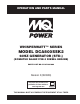
OPERATION AND PARTS MANUAL WHISPERWATT™ SERIES MODEL DCA800SSK2 60HZ GENERATOR (STD.) (KOMATSU SAA6D170E-3 DIESEL ENGINE) PARTS LIST NO. C5871301004 Revision # (09/03/09) To find the latest revision of this publication, visit our website at: www.mqpower.com THIS MANUAL MUST ACCOMPANY THE EQUIPMENT AT ALL TIMES.
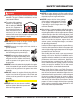
PROPOSITION 65 WARNING Diesel engine exhaust and some of PAGE 2 — DCA800SSK2 60 HZ GENERATOR • OPERATION AND PARTS MANUAL — REV.
REPORTING SAFETY DEFECTS If you believe that your vehicle has a defect that could cause a crash or could cause injury or death, you should immediately inform the National Highway Traffic Safety Administration (NHTSA) in addition to notifying Multiquip at 18004211244. If NHTSA receives similar complaints, it may open an investigation, and if it finds that a safety defect exists in a group of vehicles, it may order a recall and remedy campaign.
TABLE OF CONTENTS DCA800SSK2 60 Hz Generator Proposition 65 Warning ........................................... 2 Reporting Safety Defects......................................... 3 Table Of Contents .................................................... 4 Parts Ordering Procedures ...................................... 5 Safety Information .............................................. 6-11 Specifications ........................................................ 12 Dimensions ................................
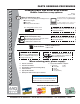
www.mqpower.com PARTS ORDERING PROCEDURES Ordering parts has never been easier! Choose from three easy options: Order via Internet (Dealers Only): Best Deal! Effective: January 1st, 2006 If you have an MQ Account, to obtain a Username and Password, E-mail us at: parts@multiquip. com. Order parts on-line using Multiquip’s SmartEquip website! N View Parts Diagrams N Order Parts N Print Specification Information To obtain an MQ Account, contact your District Sales Manager for more information.
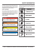
SAFETY INFORMATION Do not operate or service the equipment before reading the entire manual. Safety precautions should be followed at all times when operating this equipment. Failure to read and understand the safety messages and operating instructions could result in injury to yourself and others. Potential hazards associated with the operation of this equipment will be referenced with hazard symbols which may appear throughout this manual in conjunction with safety messages.
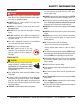
SAFETY INFORMATION GENERAL SAFETY CAUTION NEVER operate this equipment without proper protective clothing, shatterproof glasses, respiratory protection, hearing protection, steel-toed boots and other protective devices required by the job or city and state regulations. NEVER operate this equipment when not feeling well due to fatigue, illness or when under medication. NEVER operate this equipment under the influence of drugs or alcohol.
SAFETY INFORMATION ENGINE SAFETY DANGER The engine fuel exhaust gases contain poisonous carbon monoxide. This gas is colorless and odorless, and can cause death if inhaled. The engine of this equipment requires an adequate free flow of cooling air. NEVER operate this equipment in any enclosed or narrow area where free flow of the air is restricted. If the air flow is restricted it will cause injury to people and property and serious damage to the equipment or engine.
SAFETY INFORMATION FUEL SAFETY DANGER DO NOT start the engine near spilled fuel or combustible fluids. Diesel fuel is extremely flammable and its vapors can cause an explosion if ignited. Make sure the hitch and coupling of the towing vehicle are rated equal to, or greater than the trailer “gross vehicle weight rating.” ALWAYS inspect the hitch and coupling for wear. NEVER tow a trailer with defective hitches, couplings, chains, etc.
SAFETY INFORMATION ELECTRICAL SAFETY DANGER DO NOT touch output terminals during operation. Contact with output terminals during operation can cause electrocution, electrical shock or burn. The electrical voltage required to operate the generator can cause severe injury or even death through physical contact with live circuits. Turn generator and all circuit breakers OFF before performing maintenance on the generator or making contact with output terminals.
SAFETY INFORMATION BATTERY SAFETY DANGER DO NOT drop the battery. There is a possibility that the battery will explode. DO NOT expose the battery to open flames, sparks, cigarettes, etc. The battery contains combustible gases and liquids. If these gases and liquids come into contact with a flame or spark, an explosion could occur. ENVIRONMENTAL SAFETY NOTICE Dispose of hazardous waste properly. Examples of potentially hazardous waste are used motor oil, fuel and fuel filters.
SPECIFICATIONS Model Type Armature Connection Phase Standby Output Prime Output Voltage - 1 Ø Voltage - 3 Ø Frequency Speed Power Factor Aux. AC Power Aux. Voltage/Output Dry Weight Wet Weight Model Type No. of Cylinders Bore x Stroke Displacement Rated Output Starting Coolant Capacity Lube Oil Capacity Fuel Type Fuel Tank Capacity Fuel Consumption Battery Table 1.
DIMENSIONS Figure 1. Dimensions Table 3. Dimensions Reference Letter Dimension in. (mm) Reference Letter Dimension in. (mm) A 43.31 in. (1,100 mm.) H 32.68 in. (830 mm.) B 36.22 in. (920 mm.) I 39.37 in. (1000 mm.) C 27.17 in. (690 mm.) J 29.53 in. (750 mm.) D 43.31 in. (1,100 mm.) K 240.54 in. (6110 mm.) E 29.53 in. (750 mm.) L 98.43 in. (2500 mm.) F 39.37 in. (1000 mm.) M 76.77 in. (1950 mm.) G 32.68 in. (830 mm.
INSTALLATION Figure 2. Typical Generator Grounding Application PAGE 14 — DCA800SSK2 60 HZ GENERATOR • OPERATION AND PARTS MANUAL — REV.
INSTALLATION OUTDOOR INSTALLATION GENERATOR GROUNDING Install the generator in a area that is free of debris, bystanders, and overhead obstructions. Make sure the generator is on secure level ground so that it cannot slide or shift around. Also install the generator in a manner so that the exhaust will not be discharged in the direction of nearby homes. To guard against electrical shock and possible damage to the equipment, it is important to provide a good EARTH ground (Figure 2).
GENERAL INFORMATION GENERATOR The MQ Power Model DCA800SSK2 is a 640 kW generator (Figure 3) that is designed as a high quality portable (requires a trailer for transport) power source for telecom sites, lighting facilities, power tools, submersible pumps and other industrial and construction machinery.
MAJOR COMPONENTS Table 4. Generator Major Components ITEM NO. DESCRIPTION 1 Air Filter Assembly 2 Muffler Assembly 3 Fuel Tank Assembly 4 Engine Operating Panel Assembly 5 Battery Assembly 6 Output Terminal Panel Assembly 7 Generator Assembly 8 Generator Control Panel Assembly 9 Engine Control Panel Assembly Figure 3. Major Components DCA800SSK2 60 HZ GENERATOR • OPERATION AND PARTS MANUAL — REV.
GENERATOR CONTROL PANEL Figure 4. Generator Control Panel The definitions below describe the controls and functions of the DCA800SSK2 Generator Control Panel (Figure 4). 1. AC Voltmeter — Indicates the output voltage present at the U,V, and W Output Terminal Lugs. 2. Pilot Lamp — Indicates the system is running. 3. Panel Light — Normally used in dark areas or at night time. When activated, panel lights will illuminate.
GENERATOR CONTROL PANEL 14. Auto On/Off Engine Controller (MPEC) — This controller has a vertical row of status LED’s (inset), that when lit, indicate that an engine malfunction (fault) has been detected. When a fault has been detected the engine controller will evaluate the fault and all major faults will shutdown the generator. During cranking cycle, The MPEC will attempt to crank the engine for 10 seconds before disengaging.
ENGINE OPERATING PANEL Figure 5. Engine Operating Panel The definitions below describe the controls and functions of the DCA800SSK2 Engine Operating Panel (Figure 5). 1. Battery Switch — This switch should be set to the ON position during normal operation. When the engine has been stop, place this switch in the OFF position. DO NOT turn this switch during normal operation, it could cause damage to the electrical equipment. 2. Engine Speed Switch — This switch controls the speed of the engine (low/high).
NOTES DCA800SSK2 60 HZ GENERATOR • OPERATION AND PARTS MANUAL — REV.
OUTPUT TERMINAL PANEL FAMILIARIZATION OUTPUT TERMINAL PANEL OUTPUT TERMINAL FAMILIARIZATION The Output Terminal Panel (Figure 6) shown below is located on the righthand side (left from control panel) of the generator. Lift up on the cover to gain access to receptacles and terminal lugs. The “Output Terminal Panel ” (Figure 6) is provided with the following: NOTICE Terminal legs “O” and “Ground” are considered bonded grounds.
OUTPUT TERMINAL PANEL FAMILIARIZATION Twist Lock Dual Voltage 240/139 VAC Receptacles Connecting Loads There are three 240/139V, 50 amp auxiliary twistlock (CS6369) receptacles (Figure 7) provided on the output terminal panel.. Loads can be connected to the generator by the Output Terminal Lugs or the convenience receptacles (Figure 9). Make sure to read the operation manual before attempting to connect a load to the generator.
LOAD APPLICATION SINGLE PHASE LOAD THREE PHASE LOAD Always be sure to check the nameplate on the generator and equipment to insure the wattage, amperage, frequency, and voltage requirements are satisfactorily supplied by the generator for operating the equipment. When calculating the power requirements for 3phase power use the following equation: Generally, the wattage listed on the nameplate of the equipment is its rated output.
GENERATOR OUTPUTS GENERATOR OUTPUT VOLTAGES Generator Amperage A wide range of voltages are available to supply voltage for many different applications. Voltages are selected by applying jumpers (6) to the voltage changeover board (Figure 11). To obtain some of the voltages as listed in Table 7 (see below) will require a fine adjustment using the voltage regulator (VR) control knob located on the control panel. Table 8 shows the maximum amps the generator can provide.
GENERATOR OUTPUTS/GAUGE READING HOW TO READ THE AC AMMETER AND AC VOLTAGE GAUGES The AC ammeter and AC voltmeter gauges are controlled by the AC ammeter and AC voltmeter changeover switches. Both of these switches are located on the control panel and DO NOT effect the generator output. They are provided to help observe how much power is being supplied, produced at the UVWO terminals lugs.
OUTPUT TERMINAL PANEL CONNECTIONS UVWO TERMINAL OUTPUT VOLTAGES Various output voltages can be obtained using the UVWO output terminal lugs. The voltages at the terminals are dependent on the placement of the jumpers plates (6) on the Voltage ChangeOver Board (Figure 17) and the adjustment of the Voltage Regulator Control Knob.
OUTPUT TERMINAL PANEL CONNECTIONS 3Ø-480V UVWO Terminal Output Voltages 1Ø-480V UVWO Terminal Output Voltages 1. Jumper the voltage changeover board for 480V operation as shown in Figure 22. This configuration uses 6 jumper plates in 3 different positions. Remember there are 2 jumper plates at every position. Every jumper plate must be used. 1. Make sure the voltage changeover board is jumpered for 480V operation as shown in Figure 22. Figure 22. Voltage ChangeOver Board 480V Configuration 2.
INSPECTION/SETUP CIRCUIT BREAKERS To protect the generator from an overload, a 3pole, 2500 amp, main circuit breaker is provided to protect the U,V, and W Output Terminals from overload. In addition, three 50 amp load circuit breakers have been provided to protect the auxiliary receptacles from overload. Make sure to switch ALL circuit breakers to the OFF position prior to starting the engine. FUEL CHECK DANGER Fuel spillage on a hot engine can cause a fire or explosion.
INSPECTION/SETUP Refueling Procedure: WARNING 2. Open cabinet doors on the “right side” of the generator (from generator control panel position). Remove fuel cap and fill tank (Figure 29). Diesel fuel and its vapors are dangerous to your health and the surrounding environment. Avoid skin contact and/or inhaling fumes. 1. Level Tanks — Make sure fuel cells are level with the ground. Failure to do so will cause fuel to spill from the tank before reaching full capacity (Figure 28).
INSPECTION/SETUP COOLANT (ANTIFREEZE/SUMMER COOLANT/ WATER) Komatsu recommends antifreeze/summer coolant for use in their engines, which can be purchased in concentrate (and mixed with 50% demineralized water) or prediluted. See the Komatsu Engine Owner’s Manual for further details. CLEANING THE RADIATOR The engine may overheat if the radiator fins become overloaded with dust or debris. Periodically clean the radiator fins with compressed air.
INSPECTION/SETUP BATTERY When connecting battery do the following: This unit is of negative ground DO NOT connect in reverse. Always maintain battery fluid level between the specified marks. Battery life will be shortened, if the fluid level are not properly maintained. Add only distilled water when replenishment is necessary. 1. NEVER connect the battery cables to the battery terminals when the MPEC Control Switch is in either the MANUAL position.
GENERATOR STARTUP PROCEDURE (MANUAL) BEFORE STARTING CAUTION 3. Place the three auxiliary circuit breakers (Figure 36) in the OFF position prior to starting the engine. The engine’s exhaust contains harmful emissions. ALWAYS have adequate ventilation when operating. Direct exhaust away from nearby personnel. WARNING NEVER manually start the engine with the main, or auxiliary circuit breakers in the ON (closed) position.
GENERATOR STARTUP PROCEDURE (MANUAL) STARTING (MANUAL) 1. Set the battery ON/OFF switch (Figure 39) to the "ON" position. 6. The generator’s frequency meter (Figure 44) should be displaying the 60 cycle output frequency in HERTZ. Figure 39. Battery Switch (ON) 2. Place the engine speed switch in the "LOW" position (Figure 40). Figure 44. Frequency Meter 7. The generator’s ACvoltmeter (Figure 45) will display the generator’s output in VOLTS.. Figure 40. Engine Speed Switch (Low) 3.
GENERATOR STARTUP PROCEDURE (MANUAL) 14. Press the main circuit breaker "ON" switch (Figure 52). Figure 52. Main Circuit Breaker ON Switch Figure 48. Ammeter (No Load) 11. The engine oil pressure gauge (Figure 49) will indicate the oil pressure of the engine. Under normal operating conditions the oil pressure is approximately 28 to 85 psi. (193~586 kPa). 15. Verify that the main circuit breaker "ON" lamp (Figure 53) is lit (ON). Figure 53. Main Circuit Breaker ON Lamp Figure 49. Oil Pressure Gauge 16.
GENERATOR STARTUP PROCEDURE (AUTO MODE) STARTING (AUTO MODE) CAUTION When connecting the generator to a isolation (transfer) switch, ALWAYS have power applied to the generator’s internal battery charger. This will ensure that the engine will not fail due to a dead battery. DANGER Before connecting this generator to any building’s electrical system, a licensed electrician must install an isolation (transfer) switch. Serious damage to the building’s electrical system may occur without this transfer switch.
GENERATOR SHUTDOWN PROCEDURES NORMAL SHUTDOWN PROCEDURE EMERGENCY SHUTDOWN PROCEDURE To shutdown the generator, use the following procedure: 1. To stop the engine in the event of an emergency, PUSH the emergency stop button (Figure 61) inward. This button is located on the engine operating panel, see Figure 5. 1. Place the three auxiliary circuit breakers in the OFF position (Figure 36) 2. Place the engine speed switch (Figure 58) in the “LOW” (down) position. Figure 58.
MAINTENANCE Table 12.
MAINTENANCE If the engine is operating in very dusty or dry grass conditions, a clogged air cleaner will result. This can lead to a loss of power, excessive carbon buildup in the combustion chamber and high fuel consumption. Change air cleaner more frequently if these conditions exists. FUEL TANK INSPECTION In addition to cleaning the fuel tank, the following components should be inspected for wear: FUEL ADDITION Rubber Suspension — look for signs of wear or deformity due to contact with oil.
MAINTENANCE CHECK OIL LEVEL RADIATOR CLEANING Check the crankcase oil level prior to each use, or when the fuel tank is filled. Insufficient oil may cause severe damage to the engine. Make sure the generator is level. The oil level must be between the two notches on the dipstick as shown in Figure 26. The radiator (Figure 64) should be sprayed (cleaned) with a high pressure washer when excessive amounts of dirt and debris have accumulated on the cooling fins or tube.
MAINTENANCE JACKET WATER HEATER AND INTERNAL BATTERY CHARGER 120 VAC INPUT RECEPTACLES (OPTIONAL) This generator can be optionally equipped with two 120 VAC, 20 amp input receptacles located on the output terminal panel. The purpose of these receptacles is to provide power via commercial power to the jacket water heater and internal battery charger. If the generator will be used daily, the battery should normally not require charging.
TRAILER MAINTENANCE TRAILER MAINTENANCE This section is intended to provide the user with generic trailer service and maintenance information. The service and maintenance guidelines referenced in this section refer to a wide range of trailers. Remember periodic inspection of the trailer will ensure safe towing of the generator and will prevent personal injury and damage to the equipment. The definitions below describe some of the major components of a typical trailer that would be used with generator. 1.
TRAILER MAINTENANCE ELECTRIC BRAKES . Electrically actuated brakes (Figure 66) are similar tohydraulic brakes. the basic difference is that hydraulic brakes are actuated by an electromagnet. listed below are some of the advantages that electric brakes have over hydraulic brakes: Brake system can be manually adjusted to provide the corrected braking capability for varying road and load conditions.
TRAILER MAINTENANCE TIRES/WHEELS/LUG NUTS Suspension Tires and wheels are a very important and critical components of the trailer. When specifying or replacing the trailer wheels it is important the wheels, tires, and axle are properly matched. The Torsion axle systems, the suspension takes place inside the square tube which is filled with highly resilient rubber. It attaches directly to the trailer frame using brackets which are an integral part of the axle assembly (See Figure 67 below).
TRAILER MAINTENANCE Lug Nut Torque Requirements It is extremely important to apply and maintain proper wheel mounting torque on the trailer. Be sure to use only the fasteners matched to the cone angle of the wheel. Proper procedure for attachment of the wheels is as follows: 1. Start all wheel lug nuts by hand. 2. Torque all lug nuts in sequence (see Figure 68). DO NOT torque the wheel lug nuts all the way down. Tighten each lug nut in 3 separate passes as defined by Table 15. 3.
TRAILER WIRING DIAGRAM Figure 69. Trailer/Towing Vehicle Wiring Diagram PAGE 46 — DCA800SSK2 60 HZ GENERATOR • OPERATION AND PARTS MANUAL — REV.
GENERATOR WIRING DIAGRAM Figure 70. Generator Wiring Diagram DCA800SSK2 60 HZ GENERATOR • OPERATION AND PARTS MANUAL — REV.
GENERATOR WIRING DIAGRAM (MAIN BREAKER) Figure 71. Engine Wiring Diagram PAGE 48 — DCA800SSK2 60 HZ GENERATOR • OPERATION AND PARTS MANUAL — REV.
ENGINE WIRING DIAGRAM Figure 72. Controller Wiring Diagram DCA800SSK2 60 HZ GENERATOR • OPERATION AND PARTS MANUAL — REV.
TROUBLESHOOTING (GENERATOR) Practically all breakdowns can be prevented by proper handling and maintenance inspections, but in the event of a breakdown, use Table 16 shown below for diagnosis of the Generator. If the problem cannot be remedied, consult our company’s business office or service plant. Symptom No Voltage Output Low Voltage Output High Voltage Output Circuit Breaker Tripped Table 16.
TROUBLESHOOTING (ENGINE CONTROLLER) Practically all breakdowns can be prevented by proper handling and maintenance inspections, but in the event of a breakdown, use Table 17 (Engine Controller Troubleshooting) as a basic guideline for troubleshooting the Microprocessor Engine Controller unit (MPEC). If the problem cannot be remedied, consult our company's business office or service plant. Table 17. Engine Controller Troubleshooting (MPEC) Symptom Possible Problem Solution Low oil level? Fill oil level.
TROUBLESHOOTING (ENGINE CONTROLLER) This generator is equipped with an electronic governor for unit injection system. The engine controller (Figure 73), consists of a display, switches, trimmer, etc., for monitoring and for controlling the engine. Figure 73. Komatsu Engine Controller The definitions below describe the controls and functions of the Engine Controller (Figure 73). 1. Display — Displays engine malfunctions.
NOTES DCA800SSK2 60 HZ GENERATOR • OPERATION AND PARTS MANUAL — REV.
EXPLANATION OF CODE IN REMARKS COLUMN The following section explains the different symbols and remarks used in the Parts section of this manual. Use the help numbers found on the back page of the manual if there are any questions. NOTICE The contents and part numbers listed in the parts section are subject to change without notice. Multiquip does not guarantee the availability of the parts listed. SAMPLE PARTS LIST NO. 1 2% 2% 3 4 PART NO. PART NAME QTY. REMARKS 12345 BOLT......................1 .....
SUGGESTED SPARE PARTS DCA800SSK2 WHISPERWATT GENERATOR WITH KOMATSU SAA6D170E3 DIESEL ENGINE 1 to 3 units QTY. P/N DESCRIPTION 12..........0602046653..........AIR FILTER, ELEMENT, OUTER 6............0602046653-1 ......AIR FILTER, ELEMENT, INNER 12..........6003193320..........FUEL FILTER, ENGINE 24..........6002111231..........CARTRIDGE OIL FILTER 6............6004111171..........CARTRIDGE, CORROSION RESISTOR 6............0810105400..........FUEL FILTER, FUEL TANK 2............6240613821..........
GENERATOR ASSY. PAGE 56 — DCA800SSK2 60 HZ GENERATOR • OPERATION AND PARTS MANUAL — REV.
GENERATOR ASSY. NO. 1 1-1# 1-2# 1-3# 1-4# 1-5# 1-6# 1-7# 1-7A# 1-8# 1-9# 1-10# 1-11# 1-12# 1-13# 1-14# 1-15# 1-15A# 1-15B# 1-16# 1-16A# 1-17# 1-18 1-19 1-20 1-21# 2 2A 3 31 32 33 34 34A 34B 34C 35 4 5 6 6A 6B 7 PART NO.
GENERATOR ASSY. (CONTINUED) PAGE 58 — DCA800SSK2 60 HZ GENERATOR • OPERATION AND PARTS MANUAL — REV.
GENERATOR ASSY. (CONTINUED) NO. 8 8A 8B 9 10 11 11A 11B 12 13 14 15 16 17 18 19 20 20A 21 22 23 24 24A PART NO.
CONTROL PANEL ASSY. PAGE 60 — DCA800SSK2 60 HZ GENERATOR • OPERATION AND PARTS MANUAL — REV.
CONTROL PANEL ASSY. NO. 1 2 3 4 4A 5 5A 6 7 8 9 10 11 12 13 13A 14 15 16 17 18 18A 19 20 21 21A 21B 21C PART NO. C5224002303 C5224002103 0605011211 0601810476 0601810235 0601810467 0601810235 0601830498 0601831224 0601800480 0601800795 0601801040 0601800252 0601801041 0601810072 0601810261 0601840073 0601840100 ECU99888N600/800 0601830765 0601810161 0601810214 0207004000 0601830710 C9221100004 0040008000 0041208000 0080200007 PART NAME QTY.
CONTROL BOX ASSY. PAGE 62 — DCA800SSK2 60 HZ GENERATOR • OPERATION AND PARTS MANUAL — REV.
CONTROL BOX ASSY. NO. 1 2 3 4 5 6 7 8 9 10 11 12 13 14 15 15A 15B 16 17 18 19 20 21 22 23 23A 24 25 26 27 27A 27B 28 28A 28B 29 29A 29B 30 31 32 32A 32B 33 PART NO.
CONTROL BOX ASSY. (CONTINUED) PAGE 64 — DCA800SSK2 60 HZ GENERATOR • OPERATION AND PARTS MANUAL — REV.
CONTROL BOX ASSY. (CONTINUED) NO. 34 35 36 37 38 39 40 41 41A 41B 42 43 44 45 46 47 48 49 50 51 52 53 54 55 56 56A PART NO.
ENGINE ASSY. PAGE 66 — DCA800SSK2 60 HZ GENERATOR • OPERATION AND PARTS MANUAL — REV.
ENGINE ASSY. NO. 1 1-1 1-1A 1-2 1-3 1-4 1-4A 2 3 4 5 6 7 8 9 10 13 14 15 16 17 18 19 20 21 22 23 24 25 PART NO. C5924200134 0602046653 0602046653-1 6002111231 6004111171 6008711220 6240613821 C5304200504 C5304200604 0010118070 0030018000 0040018000 0041618000 0605000012 0030020000 0040020000 6995619380 0010118100 0030018000 0041618000 C5311100104 0017112025 0017110025 0199603100 0605515170 6162637810 C2317100503 6212617210 C5317100003 PART NAME QTY.
ENGINE ASSY. (CONTINUED) PAGE 68 — DCA800SSK2 60 HZ GENERATOR • OPERATION AND PARTS MANUAL — REV.
ENGINE ASSY. (CONTINUED) NO. 26 27 28 29 30 31 32 33 34 35 36 37 38 39 40 41 42 43 43A 44 PART NO. 0017108020 0017106030 0194200840 0605515019 0602022294 0605515074 0265800560 0603325017 C0321200004 C0321300004 0019208025 C5322600304 C5358300904 0010118030 0040018000 0041618000 C5358300804 6216849140 6735211930 6008158280 PART NAME QTY.
RADIATOR ASSY. (S/N 316346 AND ABOVE) PAGE 70 — DCA800SSK2 60 HZ GENERATOR • OPERATION AND PARTS MANUAL — REV.
RADIATOR ASSY. (S/N 316346 AND ABOVE) NO. 1 1A 2 18 19 20 21 22 23 24 25 26 27 28 29 36 37 38 39 40 41 42 43 44 45 46 47 PART NO. 6240619300 1140348160 6995619380 6240611950 0728101029 6240612010 6240612020 0101081020 0164331032 0728101029 6240611960 6240612080 6693629242 0101081025 0164331032 6162639651 0728101029 0726120913 0728100197 0803400536 0704200617 6240112550 6162144810 0729900120 6240112560 6162144810 0728900120 PART NAME QTY. REMARKS RADIATOR ASSY. .......................................1 ....
ALTERNATOR ASSY. (S/N 311209 AND ABOVE) PAGE 72 — DCA800SSK2 60 HZ GENERATOR • OPERATION AND PARTS MANUAL — REV.
ALTERNATOR ASSY. (S/N 311209 AND ABOVE) NO. 1 2 3 PART NO. 6240816150 6240816180 6008253161 PART NAME PULLEY, NON HARDENING BELT, ALTERNATOR ALTERNATOR, ASSY QTY. 1 1 1 REMARKS DCA800SSK2 60 HZ GENERATOR • OPERATION AND PARTS MANUAL — REV.
THEROMOSTAT ASSY. (S/N 316346 AND ABOVE) PAGE 74 — DCA800SSK2 60 HZ GENERATOR • OPERATION AND PARTS MANUAL — REV.
THEROMOSTAT ASSY. (S/N 316346 AND ABOVE) NO. 1 2 3 4 5 6 7 8 9 10 11 12 13 14 PART NO. 6240116410 6240116470 0101081095 0704230108 6240116480 6222116820 0101081035 0164331032 0704200415 6004216630 6162136440 6240611761 6162136481 0101081030 PART NAME HOUSING, THERMOSTAT GASKET BOLT PLUG PLATE GASKET BOLT WASHER PLUG THERMOSTAT SEAL, THERMOSTAT TUBE GASKET BOLT QTY. 1 1 5 2 1 1 2 2 1 2 ? 1 1 4 REMARKS DCA800SSK2 60 HZ GENERATOR • OPERATION AND PARTS MANUAL — REV.
WATER PUMP ASSY. PAGE 76 — DCA800SSK2 60 HZ GENERATOR • OPERATION AND PARTS MANUAL — REV.
WATER PUMP ASSY. NO. A 1$ 2$ 3$ 4$ 5$ 6$ 7$ 8$ 9$ 10$ 11$ 12$ 13$ 14$ 15$ 16$ 17 18 19 20 21 22 23 25 29 30 31 PART NO. 6240611302 6162631515 0634006305 0603006205 6240611470 6240611440 07012D0022 6240611321 6240611210 6240611410 6240611150 0704370211 07000G2140 07000G2012 0101081030 0164331032 0700072095 0101181215 6240611560 07000A3039 6150215720 0101080812 0164020816 07000G2075 6162631270 0728500180 0728701410 PART NAME QTY. REMARKS WATER PUMP ASSY.......... 1 .........
STARTER ASSY. (S/N 316346 AND ABOVE) PAGE 78 — DCA800SSK2 60 HZ GENERATOR • OPERATION AND PARTS MANUAL — REV.
STARTER ASSY. (S/N 316346 AND ABOVE) NO. 1 2 3 4 PART NO. 6008133512 6221816810 0101061645 0164331645 PART NAME STARTING MOTOR ASSY. (7.5 KW) GASKET BOLT WASHER QTY. 2 2 6 6 REMARKS DCA800SSK2 60 HZ GENERATOR • OPERATION AND PARTS MANUAL — REV.
ENGINE OPERATING PANEL ASSY. PAGE 80 — DCA800SSK2 60 HZ GENERATOR • OPERATION AND PARTS MANUAL — REV.
ENGINE OPERATING PANEL ASSY. NO. 1 2 2A 2B 3 3A 3B 4 5 6 7 8 9 10 11 12 13 14 14A 15 16 17 18 19 20 21 22 23 24 25 26 26A 27 28 28A PART NO.
OUTPUT TERMINAL ASSY. PAGE 82 — DCA800SSK2 60 HZ GENERATOR • OPERATION AND PARTS MANUAL — REV.
OUTPUT TERMINAL ASSY. NO. 1 2 3 4 4A 4B 4C 5 5A 5B 5C 6 6A 6B 6C 7 8 9 10 11 12 12A 12B 13 14 15 16 17 18 19 20 21 22 23 24 25 26 27 27A 27B 28 29 30 PART NO.
OUTPUT TERMINAL ASSY (CONTINUED). PAGE 84 — DCA800SSK2 60 HZ GENERATOR • OPERATION AND PARTS MANUAL — REV.
OUTPUT TERMINAL ASSY. (CONTINUED) NO. 31 311 32 33 34 34A 34B 35 36 37 38 39 PART NO. C5261600204 0221200110 0017106030 0601811034 0027104015 0030004000 0041204000 C4237101203 0601851780 C4237102804 C4237400804 0017106016 PART NAME CIRCUIT BREAKER BRACKET RUBBER CUSHION HEX HEAD BOLT RECEPTACLE MACHINE SCREW HEX NUT WASHER, FLAT COVER GROMMET COVER BRACKET HEX HEAD BOLT QTY. 1 1 2 3 6 6 6 1 2 1 1 2 REMARKS DCA800SSK2 60 HZ GENERATOR • OPERATION AND PARTS MANUAL — REV.
BATTERY ASSY. PAGE 86 — DCA800SSK2 60 HZ GENERATOR • OPERATION AND PARTS MANUAL — REV.
BATTERY ASSY. NO. 1 2 3 4 5 6 7 8 9 10 11 12 13 14 15 16 17 18 19 PART NO.
MUFFLER ASSY. PAGE 88 — DCA800SSK2 60 HZ GENERATOR • OPERATION AND PARTS MANUAL — REV.
MUFFLER ASSY. NO. 1 2 3 4 5 6 7 8 8A 8B 8C 9 9A 9B 10 11 12 12A 12B 12C 13 14 15 16 17 PART NO.
FUEL TANK ASSY. PAGE 90 — DCA800SSK2 60 HZ GENERATOR • OPERATION AND PARTS MANUAL — REV.
FUEL TANK ASSY. NO. 1 11 12 13 14 2 3 4 5 6 7 8 9 10 11 12 13 14 15 16 17 18 19 20 21 22 23 24 25 26 27 28 29 30 PART NO.
ENCLOSURE ASSY.#1 PAGE 92 — DCA800SSK2 60 HZ GENERATOR • OPERATION AND PARTS MANUAL — REV.
ENCLOSURE ASSY. #1 NO. 1 2 3 4 5 6 7 8 8A 9 10 10A 11 11A 12 13 14 14A 15 15A 16 17 17A 18 19 20 21 22 23 24 25 25A PART NO.
ENCLOSURE ASSY. #1 (CONTINUED) PAGE 94 — DCA800SSK2 60 HZ GENERATOR • OPERATION AND PARTS MANUAL — REV.
ENCLOSURE ASSY.#1 (CONTINUED) NO. 26 27 28 29 30 31 32 33 34 35 35A 35B 35C 36 37 38 39 40 41 42 43 44 45 46 47 48 49 50 51 52 PART NO.
ENCLOSURE ASSY. #2 PAGE 96 — DCA800SSK2 60 HZ GENERATOR • OPERATION AND PARTS MANUAL — REV.
ENCLOSURE ASSY. #2 NO. 1 1A 2 3 4 4A 5 5A 6 6A 7 8 9 9A 10 11 12 12A 13 14 15 16 17 18 19 20 21 22 23 24 25 26 27 28 29 30 31 32 32A 33 33A 34 35 36 PART NO.
ENCLOSURE ASSY. #2 (CONTINUED) PAGE 98 — DCA800SSK2 60 HZ GENERATOR • OPERATION AND PARTS MANUAL — REV.
ENCLOSURE ASSY. #2 (CONTINUED) NO. 37 38 38A 39 39A 40 40A 41 42 42A 43 44 45 46 46A 47 47A 48 49 50 50A 51 52 53 54 55 57 58 59 PART NO.
ENCLOSURE ASSY. #3 PAGE 100 — DCA800SSK2 60 HZ GENERATOR • OPERATION AND PARTS MANUAL — REV.
ENCLOSURE ASSY. #3 NO. 1 1A 2 2A 2B 3 3A 4 4A 5 5A 6 6A 7 7A 8 8A 9 9A 10 10A 11 12 13 14 15 16 17 18 18A 18B 19 19A 20 20A PART NO.
ENCLOSURE ASSY. #3 (CONTINUED) PAGE 102 — DCA800SSK2 60 HZ GENERATOR • OPERATION AND PARTS MANUAL — REV.
ENCLOSURE ASSY. #3 (CONTINUED) NO. 21 21A 22 22A 23 23A 24 24A 25 26 27 28 28A 29 29A 30 31 32 33 34 34A 34B 35 36 37 PART NO.
RUBBER SEALS ASSY. PAGE 104 — DCA800SSK2 60 HZ GENERATOR • OPERATION AND PARTS MANUAL — REV.
RUBBER SEALS ASSY. NO. 1 2 3 4 5 6 7 8 9 10 11 12 13 14 15 16 PART NO. 0228901750 0228901780 0228901800 0228901690 0228901150 0228801090 0229201950 0221201030 0228801600 0229200710 0229201840 0229200625 0228100380 0228100550 0228100120 0228100560 PART NAME RUBBER SEAL RUBBER SEAL RUBBER SEAL RUBBER SEAL RUBBER SEAL RUBBER SEAL RUBBER SEAL RUBBER SEAL RUBBER SEAL RUBBER SEAL RUBBER SEAL RUBBER SEAL RUBBER SEAL RUBBER SEAL RUBBER SEAL RUBBER SEAL QTY.
NAMEPLATE AND DECALS ASSY. PAGE 106 — DCA800SSK2 60 HZ GENERATOR • OPERATION AND PARTS MANUAL — REV.
NAMEPLATE AND DECALS ASSY. NO. 12 13 PART NO. B9521100404 B1552000103 PART NAME QTY. REMARKS DECAL : SAFETY INSTRUCTIOS ......................................1 ........... B92110040 DECAL : CAUTION..............................................................2 ........... B15200010 21 22 23 24 25 26 27 28 29 210 211 212 0800520100 0800520904 0800520814 0800564004 0800565004 0840624504 0840624604 0840624704 0840624804 B9531100604 C5551000303 C5561101003 CONTROL PANEL & BOX GROUP PLATE : ON OFF .........
NAMEPLATE AND DECALS ASSY (CONTINUED) PAGE 108 — DCA800SSK2 60 HZ GENERATOR • OPERATION AND PARTS MANUAL — REV.
NAMEPLATE AND DECALS ASSY (CONTINUED) NO. PART NO. PART NAME QTY. REMARKS 71 72 73 0800689404 0800689504 C9505300004 BATTERY GROUP DECAL : + ...................................................2 ................S2090 DECAL : ......................................................2 ................S2091 DECAL : CAUTION......................................1 ................C90530000 81 82 B9504200004 B9511100204 MUFFLER GROUP DECAL : WARNING ENGINE EXHAUST ....1 ................
NAMEPLATE AND DECALS ASSY. (CONTINUED) PAGE 110 — DCA800SSK2 60 HZ GENERATOR • OPERATION AND PARTS MANUAL — REV.
NAMEPLATE AND DECALS ASSY. (CONTINUED) NO. 11 PART NO. C1552000403 PART NAME QTY. REMARKS DECAL : HANDLING PROCEDURES .................................1 ........... C15200040 21 22 23 24 25 26 27 28 29 210 211 212 0800520100 0800520904 0800520814 0800564004 0800565004 0840624504 0840624604 0840624704 0840624804 B9531100604 C5551000303 C5561101003 CONTROL PANEL & BOX GROUP PLATE : ON OFF ................................................................1 ...........
TERMS AND CONDITIONS OF SALE — PARTS PAYMENT TERMS 5. Parts must be in new and resalable condition, in the original Multiquip package (if any), and with Multiquip part numbers clearly marked. 6. The following items are not returnable: Multiquip reserves the right to quote and sell direct to Government agencies, and to Original Equipment Manufacturer accounts who use our products as integral parts of their own products. a. SPECIAL EXPEDITING SERVICE Terms of payment for parts are net 30 days.
NOTES DCA800SSK2 60 HZ GENERATOR • OPERATION AND PARTS MANUAL — REV.
OPERATION AND PARTS MANUAL HERE’S HOW TO GET HELP PLEASE HAVE THE MODEL AND SERIAL NUMBER ON-HAND WHEN CALLING MULTIQUIP CORPORATE OFFICE 18910 Wilmington Ave Tel. (800) 421-1244 Carson, CA 90746 Fax (800) 537- 3927 Contact: mq@multiquip.com Web: www.multiquip.com MQ Power 1800 Water Ridge Rd. Tel. (800) 883-2551 Suite 500/600 Fax (972) 315-1847 Lewisville, TX 75057 Contact: mqpower@multiquip.com Web: www.mqpower.