PARTS AND OPERATION MANUAL PARTS AND OPERATION MANUAL © COPYRIGHT 2001, MULTIQUIP INC. MQ POWER DCA-60SSI2 TM WHISPERWATT GENERATOR PARTS LIST NO. 8081500G REV. #3 (09/15/01) MULTIQUIP INC. PARTS DEPARTMENT: 18910 WILMINGTON AVE. 800-427-1244 CARSON, CALIFORNIA 90746 FAX: 800-672-7877 SERVICE DEPARTMENT: 310-537-3700 800-421-1244 800-835-2551 FAX: 310-537-3927 FAX: 310-638-8046 E-mail:mq@multiquip.com • www:multiquip.
PAGE 2 — DCA-60SSI2 — PARTS AND OPERATION MANUAL — REV.
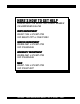
HERE'S HOW TO GET HELP PLEASE HAVE THE MODEL AND SERIAL NUMBER ON-HAND WHEN CALLING PAR TS DEP AR TMENT ARTS DEPAR ARTMENT 800/427-1244 or 310/537-3700 FAX: 800/672-7877 or 310/637-3284 VICE DEP AR TMENT SER ARTMENT SERVICE DEPAR 800/835-2551 or 310/537-3700 FAX: 310/638-8046 WARRANTY DEP AR TMENT DEPAR ARTMENT 800/835-2551 or 310/537-3700 FAX: 310/638-8046 MAIN 800/421-1244 or 310/537-3700 FAX: 310/537-3927 DCA-60SSI2 — PARTS AND OPERATION MANUAL— REV.
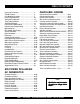
TABLE OF CONTENTS Here's How To Get Help ........................................... 3 Table Of Contents .................................................... 4 Parts Ordering Procedures ...................................... 5 Rules for Safe Operation ......................................... 6-9 Towing and Transportation ....................................... 10 Trailer Safety Guidelines .......................................... 11-17 Trailer Wiring Diagram ..............................................
PARTS ORDERING PROCEDURES ■ ■ ■ ■ ■ ■ ■ Dealer account number Dealer name and address Shipping address (if different than billing address) Return fax number Applicable model number Quantity, part number and description of each part Specify preferred method of shipment: • • • • UPS Ground UPS Second Day or Third Day* UPS Next Day* Federal Express Priority One (please provide us with your Federal Express account number)* • • Airborne Express* Truck or parcel post *Normally shipped the same day the order
RULES FOR SAFE OPERATION CAUTION: Failure to follow instructions in this manual may lead to serious injury or even death! This equipment is to be operated by trained and qualified personnel only! This equipment is for industrial use only. ■ NEVER touch the hot exhaust manifold, muffler or cylinder. Allow these parts to cool before servicing engine or generator.
RULES FOR SAFE OPERATION CAUTION: CAUTION: DO NOT touch or open any of the below mentioned components while the generator is running. Always allow sufficient time for the engine and generator to cool before performing maintenance. ■ NEVER touch output terminals during operation. This is extremely dangerous. Always stop the machine when contact with the output terminals is required. CAUTION: Radiator 1.
RULES FOR SAFE OPERATION ■ NEVER Run engine without air filter. Severe engine damage may occur. Battery CAUTION: Never over fill the battery with water above the upper limit. The battery contains acids that can cause injury to the eyes and skin. To avoid eye irritation, always wear safety glasses. Use well insulated gloves when picking up the battery. Use the following guidelines when handling the battery: ■ Always service air cleaner frequently to prevent carburetor malfunction.
RULES FOR SAFE OPERATION Transporting ■ Always shutdown engine before transporting. ■ Tighten fuel tank cap securely. ■ Drain fuel when transporting generator over long distances or bad roads. ■ Always tie-down the generator during transportation by securing the generator. ■ If generator is mounted on a trailer, make sure trailer complies with all local and state safety transportation laws. See page 10 for basic towing procedures.
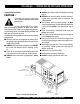
DCA-60SSI2 — TOWING RULES FOR SAFE OPERATION Towing Safety Precautions CAUTION : Check with your county or state safety towing regulations department before towing your generator. To reduce the possibility of an accident while transporting the generator on public roads, always make sure the trailer (Figure 1) that supports the generator and the towing vehicle are in good operating condition and both units are mechanically sound.
DCA-60SSIU — TRAILER-SAFETY GUIDELINES CAUTION: 4. ALWAYS make sure the trailer is in good operating condition. Check the tires for proper inflation and wear. Also check the wheel lug nuts for proper tightness. Explanation of Chart: This section is to provide the user with trailer service and maintenance information. The service and maintenance guidelines referenced in this section apply a wide range of trailers.
DCA-60SSIU —TRAILER-SPECIFICATIONS Table 1. Specifications MODEL APPLICATION FU E L C E LL BRAKE SYSTEM GVWR FRAME LENGTH FRAME WIDTH JACK STAND TRLR-10W SDW225, SGW250,TLW300 NO NO 1900LB S 96" 50" 800LB . FULL TILT WHEEL TRLR-10 DCA10, TLG12, DCA-15 NO NO 1900LB S 96" 50" 800LB . FULL TILT WHEEL TRLR-10XF DCA10, TLG-12, DCA15, TLW-300 52 GAL NO 1900LB S 96" 50" 800LB . FULL TILT WHEEL TRLR-225W WELDERS, D A 7000S S NO NO 2200LB S 85" 42" 800LB .
DCA-60SSIU —TRAILER-SPECIFICATIONS Table 1. Specifications (Con't) MODEL COUPLER TIRES WHEELS AXLE HUBS SUSPENSION ELECTRICAL TRLR-10W 2" B A LL C LA S S 2 ADJUSTABLE 175-13C 13"X4.50" 2200# 2X 2 5 LUG 3 LE A F 4 WIRE LOOM W/ 4 POLE FLAT TRLR-10 2" B A LL C LA S S 2 ADJUSTABLE 175-13C 13"X4.5" 2200#2X 2 5 LUG 3 LE A F 4 POLE FLAT TRLR-10XF 2" B A LL C LA S S 2 ADJUSTABLE 175-13C 13"X4.
DCA-60SSIU —TRAILER SAFETY GUIDELINES Brakes If your trailer has a braking system, the brakes should be inspected the first 200 miles of operation. This will allow the brake shoes and drums to seat properly. After the first 200 mile interval, inspect the brakes every 3,000 miles. If driving over rough terrain, inspect the brakes more frequently. Electric Brakes Electrically actuated brakes (Figure 2) are similar to hydraulic brakes.
DCA-60SSIU — TRAILER SAFETY GUIDELINES Figure 2. Electrical Brake Components Hydraulic/Air/Surge Brakes Hydraulic brakes (Figure 3) should not require any special attention with the exception of routine maintenance such as shoe and lining replacement. These brakes can be adjusted in the same manner as electric brakes. Brake lines should be periodically checked for cracks, kinks, or blockage.
DCA-60SSIU — TRAILER SAFETY GUIDELINES Tires/Wheels/Lug Nuts Tires and wheels are a very important and critical components of the trailer. When specifying or replacing the trailer wheels it is important the wheels, tires, and axle are properly matched. CAUTION: DO NOT attempt to repair or modify a wheel. DO NOT install in inner tube to correct a leak through the rim.
DCA-60SSIU —TRAILER SAFETY GUIDELINES Table 3. Suspension Torque Requirements Item Torque (Ft.-Lbs.) 3/8" U-BOLT MIN-30 MAX-35 7/16" U-BOLT MIN-45 MAX-60 1/2" U-BOLT MIN-45 MAX-60 SHACKLE BOLT SNUG FIT ONLY. PARTS MUST ROTATE FREELY. SPRING EYE BOLT LOCKING NUTS OR COTTER PINS ARE PROVIDED TO RETAIN NUT-BOLT ASSEMBLY. MIN-30 MAX-50 SHOULDER TYPE SHACKLE BOLT Lug Nut Torque Requirements It is extremely important to apply and maintain proper wheel mounting torque on the trailer.
DCA-60SSIU —TRAILER-WIRING DIAGRAM NOTE: LIGHTS ARE ORIENTED FROM THE DRIVER’S SEAT PAGE 18 — DCA-60SSI2 — PARTS AND OPERATION MANUAL — REV.
DCA-60SSIU —TRAILER-BRAKE TROUBLESHOOTING Table 5. Electric Brake Troubleshooting Symptom Possible Cause Solution No Brakes or Intermittent Brakes Any open circuits or broken wires? Find and correct. Any shor t circuits? Find and correct. Faulty controller? Test and correct. Any loose connections? Find and repair. Ground wire secure? Find and secure. Grease or oil on magnets or linings? Clean or replace. Connections corroded? Clean and correct cause of corrosion.
DCA-60SSIU —TRAILER-BRAKE TROUBLESHOOTING Table 6. Hydraulic Brake Troubleshooting Symptom Possible Cause Solution No Brakes Brake line broken or kinked? Repair or replace. Weak Brakes or Brakes Pull to One Side Brake lining glazed? Reburnish or replace. Trailer overloaded? Correct weight. Brake drums scored or grooved? Machine or replace. Tire pressure correct? Inflate all tires equally. Tires unmatched on the same axle? Match tires.
DCA-60SSI2 — GENERATOR DECALS The DCA -100SSJU generator is wquipped with a number of safety decals. These decals are provided for operator safety and maintenance information. The illustration below and on the preceding pages show the decals as they appear on the machine. Should any of these decals become unreadable, replacements can be obtained from your dealer. DCA-60SSI2 — PARTS AND OPERATION MANUAL— REV.
DCA-60SSI2 — GENERATOR DECALS PAGE 22 — DCA-60SSI2 — PARTS AND OPERATION MANUAL — REV.
DCA-60SSI2 — SPECIFICATIONS Table 7. Specifications Generator Specifications Model DCA-60SSI2 Type Revolving field, self ventilated, open protected type synchronous generator Armature Connection Star with Neutral Zig Zag Phase 3 Single Standby Output 72 KVA (57.6 KW) 41.5KW Prime Output 60 KVA (48 KW) 34.6KW Voltage 240V or 480V 240/120V Frequency 60 Hz Speed 1800 rpm Power Factor 0.8 1 Aux. AC Power Single Phase, 60 Hz Voltage 120 V Output 4.8 KW (2.
DCA-60SSI2 — GENERAL INFORMATION DCA-60SSI2 FAMILIARIZATION Open Delta Excitation System Generator The DCA-60SSI2 generator is equipped with the state of ator the art "Open-Delta" excitation system. The open delta The MQ Power Model DCA-60SSI2 is a 48 kW gener generator that is designed as a high quality portable (requires a trailer system consist of an electrically independent winding wound for transport) power source for telecom sites, lighting among stationary windings of the AC output section.
DCA-60SSI2 — MAJOR COMPONENTS Figure 6. Major Components DCA-60SSI2 — PARTS AND OPERATION MANUAL— REV.
DCA-60SSI2 — DIMENSIONS (TOP, SIDE AND FRONT) Figure 7. Dimensions PAGE 26 — DCA-60SSI2 — PARTS AND OPERATION MANUAL — REV.
NOTE PAGE DCA-60SSI2 — PARTS AND OPERATION MANUAL— REV.
DCA-60SSI2 — CONTROL PANEL Figure 8. Control Panel PAGE 28 — DCA-60SSI2 — PARTS AND OPERATION MANUAL — REV.
DCA-60SSI2 — CONTROL PANEL The definitions below describe the controls and functions of the DCA-60SSI2 " Control Panel " (Figure 8). 1. Frequency Meter – Indicates the output frequency in hertz (Hz). Normally 60 Hz ±1 Hz . 2. AC Ammeter – Indicates the amount of current the load is drawing from the generator. 3. ACVoltmeter – Indicates the single phase output voltage present at the UNV terminals. 4. Pilot Lamp - This lamp indicates the load is not properly set.
DCA-60SSI2 — ENGINE OPERATING PANEL Figure 9. Engine Operating Panel PAGE 30 — DCA-60SSI2 — PARTS AND OPERATION MANUAL — REV.
DCA-60SSI2 — ENGINE OPERATING PANEL The definitions below describe the controls and functions of the DCA-60SSI2 " Engine Operating Panel " (Figure 9). 1. Oil Pressure Gauge – Normal operation should be about 25 psi. When starting the generator the oil pressure may read a bit higher, but after the engine warms up the oil pressure should return to normal. 2. Panel light - Normally used in dark places or at night. When activated, panel will luminate.
DCA-60SSIU — OUTPUT TERMINAL PANEL Output Terminal Panel The output control panel is located on the rear (control panel) end of the generator. The UNV lugs are protected by a face plate cover that can be secured in the close position by a pad lock. 120 Volt Receptacle One GFCI Duplex NEMA 5-20R (120V, 20 Amp) receptacle is located on the output terminal. This receptacle can be used anytime the generator is in operation. The receptacle is controlled by the circuit breaker located on the control panel.
DCA-60SSIU — OUTPUT TERMINAL VOLTAGE SELECTION DCA-60SSIU NOTE Legs O and Ground are considered Bonded Grounds. Figure 12. Output Panel Location DCA-60SSI2 — PARTS AND OPERATION MANUAL— REV.
DCA-60SSIU — OUTPUT AMPERAGE SETUP Output Terminal Panel Available Voltages A wide range of voltages are available to supply load to many different applications. Voltages may be selected by using the voltage selector switch and depending how you hookup your hard wire connection to the generator. To obtain some of the voltages listed, fine adjustment with the voltage regulator on the control panel is necessary. See Table 8 for available voltages the generator will supply.
DCA-60SSIU — OUTPUT AMPERAGE SETUP Receptacle Use When the UVWO terminals are providing power, the receptacle power availability will decrease. How To Read The Output Terminal Gauges. The gauges (Figure 15 and 17) and change-over switches on the control panel DO NOT effect the generator output. They are to help observe how much power is being supplied at the UVWO legs.
DCA-60SSIU — OUTPUT VOLTAGE SETUP 240/120V Hard Wire Hookup 480/240V Hard Wire Hookup With the voltage selector set and locked at ‘single phase 240/120’ and using single phase 120 volts, the generator will provide three legs available with 100 amps each on three different circuits (Figure 18). With the voltage selector set and locked at ‘3 phase 480/ 277’ (Figure 19) and using the 3-phase 240 hookup, it will provide one circuit available at 108 amps with any two wires plus the ground (Figure 20).
DCA-60SSIU — OUTPUT VOLTAGE SETUP Voltage Selector Switch- 3 Phase 480/277V Position The following are additional voltages available when the voltage selector switch is in the ‘3 phase 480/277V’ position. Single Phase: 480V, 440V, or 416 Volt This setting can provide single phase power at 480, 440, or 416 volts.
DCA-60SSIU — OUTPUT VOLTAGE SETUP Voltage Selector Switch- 3 Phase 240/139V Position The following are additional voltages available when the voltage selector switch is in the ‘3 phase 240/139V’ position. Figure 25. Voltage Selector Switch 240/139V Three Phase Position Single Phase: 240V, 220V, or 208 Volt This setting can provide single phase power at 240, 220, or 208 volts.
DCA-60SSIU — OUTPUT VOLTAGE SETUP Voltage Selector Switch- Single Phase 240/120V Position The following are additional voltages available when the voltage selector switch is in the ‘single phase 240/120V’ position. Single Phase: 120 Volt This setting can provide single phase power at 120 volts. After hooking up the hard wires to the lugs as shown in Figure 31, 120 volts can be obtained with the voltage regulator knob turned to fine tune. Figure 31. Hard Wire Hookup for Single Phase, 120 volt Figure 29.
DCA-60SSI2 — INSTALLATION Outdoor Installation Install the generator in a location where it will not be exposed to rain or sunshine. Make sure the generator is on secure level ground so that it cannot slide or shift around. Also install the generator in a manner so that the exhaust will not be discharged in the direction of nearby homes. CAUTION : An electric shock may happen when vibrators are used.
DCA-60SSI2 — INSTALLATION Figure 32. Typical Generator Grounding Application DCA-60SSI2 — PARTS AND OPERATION MANUAL— REV.
DCA-60SSI2 — PRE-SETUP General Inspection Prior to Operation Circuit Breakers The DCA-60SSI2 generator has been thoroughly inspected and accepted prior to shipment from the factory. However, be sure to check for damaged parts or components, or loose nuts and bolts, which could have occurred in transit. Extension Cable To protect the generator from an overload, a 3-pole, 150 amp, main circuit breaker is provided to protect the UNV output terminals from overload.
DCA-60SSI2 — PRE-SETUP Lubrication Oil Fill the engine crankcase with lubricating oil through the filler hole, but do not overfill. Make sure the generator is level. With the dipstick inserted all the way, but without being screw into the filler hole, verify that the oil level is maintained between the two notches (Figure 33) on the dipstick. See Table 11 for proper selection of engine oil. Fuel Fill the fuel tank with clean and fresh diesel fuel. DO NOT fill the tank beyond capacity.
DCA-60SSIU — PRE-SETUP CAUTION : When adding coolant or antifreeze to the radiator, do not remove the radiator cap until the unit has completely cooled. Day-to-day addition of coolant is done from the reserve tank. When adding coolant to the radiator, DO NOT remove the radiator cap until the unit has completely cooled. See Table 12. for engine, radiator, and reserve tank coolant capacities. Make sure the coolant level in the reserve tank is always between the "H" and the "L" markings. Table 12.
DCA-60SSIU — PRE-SETUP Battery This unit is of negative ground. DO NOT connect in reverse. Always maintain battery fluid level between the specified marks. Battery life will be shortened, if the fluid level is not properly maintained. Add only distilled water when replenishment is necessary. DO NOT over fill. The battery is sufficiently charged if the specific gravity of the battery fluid is 1.28 (at 68° F). If the specific gravity should fall to 1.
DCA-60SSI2 — LOAD APPLICATION Single Phase Load CAUTION: Always be sure to check the nameplate on the generator and equipment to insure the wattage, amperage and frequency requirements are satisfactorily supplied by the generator for operating the equipment. Motors and motor-driven equipment draw much greater current for starting than during operation. Generally, the wattage listed on the nameplate of the equipment is its rated output.
DCA-60SSI2 — GENERATOR START-UP PROCEDURE WARNING: The engine's exhaust contains harmful W AY S ventilate the emissions. A LLW exhaust when operating inside tunnels, excavations or buildings. Direct exhaust away from nearby personnel. 2. Connect the load to the UVW terminals as shown in Figure 37. These terminals can be found on the output terminal panel, (see page 22 Figure 6). To gain access to the output terminals lift the UVW cover.
DCA-60SSI2 — GENERATOR START-UP PROCEDURE 4. Close all engine enclosure doors (Figure 39). 8. Once the preheat indicator lights, turn the key to ‘START’ (Figure 43). After the engine cranks, release the key to ‘RUN’. Figure 43. Starter Switch (Start) Figure 39. Engine Enclosure Doors 5. Check the voltage selection switch (Figure 40) is at the desired voltage. 9. Pull the engine throttle lever and turn left until the lever sets on the knob (Figure 44). Figure 44. Engine Throttle Lever (Up) Figure 40.
DCA-60SSI2 — GENERATOR START-UP PROCEDURE 15. The charging ammeter (Figure 51) will indicate if the battery is properly charged. Figure 47. Voltage Adjust Control Knob 12. The ammeter (Figure 48) will indicate zero amps with no load applied. When a load is applied, this meter will indicate the amount of current that the load is drawing from the generator’s alternator. 20 40 0 Figure 51. Charging Ammeter 16.
DCA-60SSI2 — GENERATOR SHUT-DOWN PROCEDURE ENGINE SHUTDOWN To shutdown the generator, use the following procedure: 1. Switch both the MAIN, GFCI and LOAD circuit breakers (Figure 55)to the “OFF” position. EMERGENCY STOP 1. To stop the engine in the event of an emergency, switch the MAIN, GFCI and LOAD circuit breakers to ‘OFF’ position. 2. Turn the key switch to ‘STOP’. Figure 55. Main, GFCI and Load circuit breakers 2. Turn to the right and press in the engine throttle lever (Figure 56). Figure 56.
NOTE PAGE DCA-60SSI2 — PARTS AND OPERATION MANUAL— REV.
DCA-60SSIU — MAINTENANCE General Inspection Cleaning the Fuel Strainer Prior to each use, the generator should be cleaned and inspected for deficiencies. Check for loose, missing or damaged nuts, bolts or other fasteners. Also check for fuel, oil, and coolant leaks. Clean the fuel strainer if it contains dust or water. Remove dust or water in the strainer cap and wash it in gasoline. Securely fasten the fuel strainer cap so that fuel will not leak.
DCA-60SSIU — MAINTENANCE Feed Pump Strainer Cleaning The strainer is incorporated in the feed pump inlet side joint bolt. Clean the strainer with compressed air and rinse it in the fuel oil. Flushing Out Radiator and Replacing Coolant 1. Open both cocks located at the crankcase side and at the lower part of the radiator and drain coolant. Open the radiator cap while draining. Remove the overflow tank and drain. 2. Check hoses for softening and kinks. Check clamps for signs of leakage. 3.
DCA-60SSIU — MAINTENANCE Valve Clearance Check 1. In order to bring No. 1 or No. 4 cylinder to top dead center in the compression stroke, align the notched line on the crank pulley with TDC mark on the timing gear case cover. 3. Remove the timing check hole cover at the front of injection pump to check the alignment between the pointer “a” on the injection pump gear lock plate and the projected area mark “b” on the timing gear case. 4. If “a” and “b” are in alignment, the timing is set correctly.
DCA-60SSIU — MAINTENANCE INSPECTION / MAINTENANCE ENGINE GENERATOR 10 Hrs DAILY Check Engine Fluid Levels X Check Air Cleaner X Check Battery Acid Level X Check Fan Belt Condition X Check for Leaks X Check for Loosening of Parts X 250 Hrs Replace Engine Oil and Filter *1 X Clean Air Filter X Drain Bottom of Fuel Tank X Clean Unit, Inside and Outside X 500 Hrs Change Fuel Filter *2 X Clean Radiator and Check Coolant Protection Level X 1000 Hrs Replace Air Filter Element X Ch
DCA-60SSI2 — GENERATOR WIRING DIAGRAM PAGE 56 — DCA-60SSI2 — PARTS AND OPERATION MANUAL — REV.
DCA-60SSI2 — ENGINE WIRING DIAGRAM DCA-60SSI2 — PARTS AND OPERATION MANUAL— REV.
DCA-60SSI2 — TROUBLESHOOTING (ENGINE) Practically all breakdowns can be prevented by proper handling and maintenance inspections, but in the event of a breakdown, use the tables shown for diagnosis based on the Engine Troubleshooting (Table 16). If the problem cannot be remedied, consult our company's business office or service plant. TABLE 16. ENGINE TROUBLESHOOTING SYMPTOM Engine does not start. POSSIBLE PROBLEM SOLUTION No fuel? Replenish fuel. Air in the fuel system? Bleed system.
DCA-60SSI2 — TROUBLESHOOTING (ENGINE) TABLE 16. ENGINE TROUBLESHOOTING (CONTINUED) SYMPTOM Engine revolution is not smooth. Either white or blue exhaust gas is observed. Either black or dark gray exhaust gas is observed. Deficient output. POSSIBLE PROBLEM SOLUTION Fuel filter clogged or dirty? Clean or change. Air cleaner clogged? Clean or change. Fuel leak due to loose injection pipe retaining nut? Tighten nut. Injection pump malfunctioning? Repair or replace.
DCA-60SSI2 — TROUBLESHOOTING (GENERATOR/ENGINE) Practically all breakdowns can be prevented by proper handling and maintenance inspections, but in the event of a breakdown, use the tables shown for diagnosis based on the Engine and Radiator Troubleshooting (Table 7). If the problem cannot be remedied, consult our company's business office or service plant. TABLE 17.
NOTE PAGE DCA-60SSI2 — PARTS AND OPERATION MANUAL— REV.
EXPLANATION OF CODE IN REMARKS COLUMN How to read the marks and remarks used in this parts book. Items Found In the “Remarks” Column Serial Numbers-Where indicated, this indicates a serial number range (inclusive) where a particular part is used. Model Number-Where indicated, this shows that the corresponding part is utilized only with this specific model number or model number variant.
DCA-60SSI2 — SUGGESTED SPARE PARTS DCA-60SSI2 W/ISUZU 6BG1 DIESEL ENGINE 1 TO 3 UNITS Qty. P/N Description 1 ......... 0601805869 ......... CIRCUIT BREAKER 1 ......... 0601820671 ......... AUTOMATIC VOLTAGE REGULATOR 1 ......... 0601840073 ......... RHEOSTAT VOLTAGE REGULATOR 1 ......... 0601840121 ......... KNOB REHOSTAT 1 ......... 0602013901 ......... RADIATOR HOSE, UPPER 1 ......... 0602013160 ......... RADIATOR HOSE, LOWER 5 ......... 1878100753 ......... OIL FILTER 5 ......... X132400240 ........
DCA-60SSI2 --- GENERATOR ASSY. GENERATOR ASSY. PAGE 64 — DCA-60SSI2 — PARTS AND OPERATION MANUAL — REV.
DCA-60SSI2 --- GENERATOR ASSY. GENERATOR ASSY. NO. PART NO.
DCA-60SSI2 --- GENERATOR ASSY. GENERATOR ASSY. PAGE 66 — DCA-60SSI2 — PARTS AND OPERATION MANUAL — REV.
DCA-60SSI2 --- GENERATOR ASSY. GENERATOR ASSY. NO. PART NO. 19 8041331014 20 0105050616 21 8001333003 22 0010106030 23 0040006000 24 952404470 25 015091025 26 030210250 27 8051332003 8051332014 28 0605000010 29 0030012000 0040012000 ITEM QTY. REMARKS COVER, END BRACKET 1 HEX. HEAD BOLT ........................... 8 ........... REPLACES 0017106012 COVER, END BRACKET 1 HEX. HEAD BOLT 2 LOCK WASHER 2 PLAIN WASHER ............................ 2 ........... REPLACES 0041206000 HEX. HEAD BOLT ...................
DCA-60SSI2 --- CONTROL BOX ASSY. CONTROL BOX ASSY. PAGE 68 — DCA-60SSI2 — PARTS AND OPERATION MANUAL — REV.
DCA-60SSI2 --- CONTROL BOX ASSY. CONTROL BOX ASSY. NO. PART NO.
DCA-60SSI2 --- CONTROL BOX ASSY. CONTROL BOX ASSY. PAGE 70 — DCA-60SSI2 — PARTS AND OPERATION MANUAL — REV.
DCA-60SSI2 --- CONTROL BOX ASSY. CONTROL BOX ASSY. NO. PART NO. 30 31 32 33 34 35 36 37 38 39 40 3331824003 0027105016 0030005000 0805001304 0845056404 031108160 020108060 0027105010 8081814503 0017106016 8081814604 0017106016 011208025 ITEM QTY. REMARKS STOPPER, CONTROL PANEL 1 MACHINE SCREW 2 HEX. NUT 2 SET SCREW ................................................. 2 ....... UP TO S/N3655377 SET SCREW ................................................. 2 ....... S/N3655378~ PLAIN WASHER ..................
DCA-60SSI2 ENGINE AND RADIATOR ASSY. ENGINE AND RADIATOR ASSY. PAGE 72 — DCA-60SSI2 — PARTS AND OPERATION MANUAL — REV.
DCA-60SSI2 ENGINE AND RADIATOR ASSY. ENGINE AND RADIATOR ASSY. NO. PART NO. ITEM QTY. REMARKS 1 0602000100 ENGINE ........................................... 1 ......... ISUZU 6BD1; UP TO S/N3656070 B4924200114 ENGINE ........................................... 1 ......... ISUZU A6BD1; S/N3656071~ 2 0602010802 RADIATOR ....................................... 1 ......... H190110000 3 0017108020 HEX. HEAD BOLT 6 4 0602013901 RADIATOR HOSE ............................ 1 .........
DCA-60SSI2 ENGINE AND RADIATOR ASSY. ENGINE AND RADIATOR ASSY. PAGE 74 — DCA-60SSI2 — PARTS AND OPERATION MANUAL — REV.
DCA-60SSI2 ENGINE AND RADIATOR ASSY. ENGINE AND RADIATOR ASSY. NO. PART NO. ITEM 28 29 30 31 32 33 34 35 36 37 38 39 40 41 42 43 44 45 46 47 48 49 50 51 52 53 74522051104 0805013704 0805014204 3362054104 3362051003 0802024004 0802010204 7452053104 0605515158 0017108020 0030008000 0845031303 0802081104 7452082504 0017108020 0017106025 0199500470 0199500175 0193602000 0605515013 0193100950 0605515007 0193800850 0605515019 7452220404 8970209410 QTY.
DCA-60SSI2 --- ENGINE OPERATING PANEL ASSY. ENGINE OPERATING PANEL ASSY. PAGE 76 — DCA-60SSI2 — PARTS AND OPERATION MANUAL — REV.
DCA-60SSI2 --- ENGINE OPERATING PANEL ASSY. ENGINE OPERATING PANEL ASSY. NO. PART NO. ITEM QTY. REMARKS 1 7452111103 OPERATING PANEL 1 2 7452142014 SLIDE BAR 1 3 0601840190 KNOB ............................................... 1 ......... REPLACES 0805012904 4 020108060 HEX. NUT ........................................ 1 ......... REPLACES 0036003000 5 7452140504 BRACKET, GOVERNOR ROD 1 6 020108060 HEX. NUT ........................................ 2 .........
DCA-60SSI2 --- ENGINE OPERATING PANEL ASSY. ENGINE OPERATING PANEL ASSY. PAGE 78 — DCA-60SSI2 — PARTS AND OPERATION MANUAL — REV.
DCA-60SSI2 --- ENGINE OPERATING PANEL ASSY. ENGINE OPERATING PANEL ASSY. NO. PART NO. ITEM QTY. REMARKS 36 0602180108 BALL JOINT 1 37 020106050 HEX. NUT ........................................ 3 ......... REPLACES 0030006000 38 952404470 PLAIN WASHER .............................. 1 ......... REPLACES 0041206000 39 8111860103 SET BOARD, OUPUT TERMINAL 1 40 0801830204 OUTPUT TERMINAL 5 41 0801830704 HEX. HEAD BOLT 5 42 0039312000 HEX.
DCA-60SSI2 --- BATTERY ASSY. BATTERY ASSY. PAGE 80 — DCA-60SSI2 — PARTS AND OPERATION MANUAL — REV.
DCA-60SSI2 --- BATTERY ASSY. BATTERY ASSY. NO. PART NO. 1 0168409541 2 0805003904 3 0805004004 4 0805002904 5 031108160 6 0040008000 7 0037808000 8 0215260065 9 0211160180 10 0215860100 11 0602220310 020800800 12 0602220311 0208008000 13 0845040414 14 0845041304 ITEM QTY. REMARKS BATTERY ......................................... 2 ......... 95E41R BATTERY SHEET 2 BATTERY BAND 2 BATTERY BOLT 4 PLAIN WASHER .............................. 4 .........
DCA-60SSI2 --- MUFFLER ASSY. MUFFLER ASSY. PAGE 82 — DCA-60SSI2 — PARTS AND OPERATION MANUAL — REV.
DCA-60SSI2 --- MUFFLER ASSY. MUFFLER ASSY. NO. PART NO. 1 8082330303 2 1141450690 3 9091103100 4 3802311122 5 012210020 6 7452330303 7 B4334200404 8 011008035 9 031108160 10 0040008000 11 0030008000 12 1382320003 13 011208030 14 031108160 15 020108060 16 3342354104 17 3342354004 18 3342328104 19 031108160 20 020108060 21 3342359004 22 011208025 ITEM QTY. REMARKS EXHAUST PIPE 1 GASKET .......................................... 1 ......... REPLACES 9221160010 HEX. NUT ........................................
DCA-60SSI2 --- FUEL TANK ASSY. FUEL TANK ASSY. PAGE 84 — DCA-60SSI2 — PARTS AND OPERATION MANUAL — REV.
DCA-60SSI2 --- FUEL TANK ASSY. FUEL TANK ASSY. NO. PART NO. 1 1-1 1-2 1-3 1-4 2 3 4 5 6 7 8 9 10 11 12 13 14 7455510303 0810105004 0810105400 0193100255 0605515079 7455523304 0805003414 011008020 0207008000 020108060 0222100200 0131906000 0191301150 0191300670 0605515109 0845032204 0845047504 0150000018 0802011104 ITEM QTY. REMARKS FUEL TANK 1 CAP, FUEL TANK 1 FUEL FILTER 1 FUEL GAUGE HOSE 1 HOSE BAND 2 TANK BAND 2 PAD, TANK BAND 4 HEX. HEAD BOLT ............................ 2 .........
DCA-60SSI2 --- ENCLOSURE ASSY. ENCLOSURE ASSY. UP TO S/N3656070 ADD THE FOLLOWING DIGITS AFTER THE PART NUMBER WHEN ORDERING ANY PAINTED PANEL TO INDICATE COLOR OF UNIT: 1-ORANGE 5 -BLACK 2-WHITE 6 -CATERPILLAR YELLOW 3 -SPECTRUM GRAY 7 -CATO GOLD 4 -SUNBELT GREEN 8 -RED THE SERIAL NUMBER MAY BE REQUIRED. PAGE 86 — DCA-60SSI2 — PARTS AND OPERATION MANUAL — REV.
DCA-60SSI2 --- ENCLOSURE ASSY. ENCLOSURE ASSY. NO. PART NO.
DCA-60SSI2 --- ENCLOSURE ASSY. ENCLOSURE ASSY. UP TO S/N3656070 ADD THE FOLLOWING DIGITS AFTER THE PART NUMBER WHEN ORDERING ANY PAINTED PANEL TO INDICATE COLOR OF UNIT: 1-ORANGE 5 -BLACK 2-WHITE 6 -CATERPILLAR YELLOW 3 -SPECTRUM GRAY 7 -CATO GOLD 4 -SUNBELT GREEN 8 -RED THE SERIAL NUMBER MAY BE REQUIRED. PAGE 88 — DCA-60SSI2 — PARTS AND OPERATION MANUAL — REV.
DCA-60SSI2 --- ENCLOSURE ASSY. ENCLOSURE ASSY. NO. PART NO.
DCA-60SSI2 --- ENCLOSURE ASSY. ENCLOSURE ASSY. UP TO S/N3656070 PAGE 90 — DCA-60SSI2 — PARTS AND OPERATION MANUAL — REV.
DCA-60SSI2 --- ENCLOSURE ASSY. ENCLOSURE ASSY. NO. PART NO. 43 44 45 47 48 49 69 70 71 72 73 0845028203 0845046904 0845028304 0845047004 0017108025 0601850097 0845031504 6360510003 0600500090 0021106020 0825007362 0221806015 B4444800004 7455109713 B4444800104 7455109713 0207006000 ITEM QTY. REMARKS HINGE .................................................. 4 ............UP TO S/N3656070 HINGE .................................................. 4 ............S/N3656071~ HINGE ..............................
DCA-60SSI2 --- RUBBER SEAL ASSY. RUBBER SEAL ASSY. PAGE 92 — DCA-60SSI2 — PARTS AND OPERATION MANUAL — REV.
DCA-60SSI2 --- RUBBER SEAL ASSY. RUBBER SEAL ASSY. UP TO S/N3656070 NO. PART NO. ITEM 57 58 59 60 61 62 63 64 65 66 67 68 7455104104 7455104204 7455104304 7455104404 7455104514 7455104614 7455104714 7455104804 7455104904 0225100365 0220100365 0220200750 RUBBER SEAL RUBBER SEAL RUBBER SEAL RUBBER SEAL RUBBER SEAL RUBBER SEAL RUBBER SEAL RUBBER SEAL RUBBER SEAL RUBBER SEAL RUBBER SEAL RUBBER SEAL RUBBER SEAL ASSY. S/N3656071~ NO. PART NO.
DCA-60SSI2 --- DECALS DECAL ASSY. PAGE 94 — DCA-60SSI2 — PARTS AND OPERATION MANUAL — REV.
DCA-60SSI2 --- DECALS DECAL ASSY. NO. PART NO.
ISUZU 6BG1 — CYLINDER HEAD COVER ASSY. CYLINDER HEAD COVER ASSY. PAGE 96 — DCA-60SSI2 — PARTS AND OPERATION MANUAL — REV.
ISUZU 6BG1 — CYLINDER HEAD COVER ASSY. CYLINDER HEAD COVER ASSY. NO PART NO PART NAME 1 1111803500 CYLINDER HEAD COVER 27 9111790300 GASKET 68 9111791050 CAP NUT WASHER 69 1111730550 GASKET 75 8943401920 NUT QTY. 1 4 4 1 4 REMARKS DCA-60SSI2 — PARTS AND OPERATION MANUAL— REV.
ISUZU 6BG1 — CYLINDER HEAD ASSY. CYLINDER HEAD ASSY. PAGE 98 — DCA-60SSI2 — PARTS AND OPERATION MANUAL — REV.
ISUZU 6BG1 — CYLINDER HEAD ASSY. CYLINDER HEAD ASSY. NO PART NO 1 1111106142 2 1111411960 4* 5117210010 5A* 1117150540 5B* 1117110430 7A* 1096000051 7B* 9111291280 7C* 5112190150 7D* 5096000130 7E* 1096000160 7F 9111296010 9 9041108250 10 1825130430 11A 5197320011 11B 5197320021 12 9117776221 14 9096300260 41A 0286810200 41B 0208014250 54 9098301630 56 1093000180 81* 9096600340 112 9099167550 113 0280806100 117 9091505140 120A 1090701010 120B 1090701000 168 5117770551 PART NAME QTY.
ISUZU 6BG1 — CYLINDER BLOCK ASSY. CYLINDER BLOCK ASSY. PAGE 100 — DCA-60SSI2 — PARTS AND OPERATION MANUAL — REV.
ISUZU 6BG1 — CYLINDER BLOCK ASSY. CYLINDER BLOCK ASSY. NO. PART NO.
ISUZU 6BG1 — CYLINDER BLOCK ASSY. CYLINDER BLOCK ASSY. PAGE 102 — DCA-60SSI2 — PARTS AND OPERATION MANUAL — REV.
ISUZU 6BG1 — CYLINDER BLOCK ASSY. CYLINDER BLOCK ASSY. NO. PART NO. PART NAME 113* 130* 136 137 162 179 218 219 220 236 242 267 269 279 281 335A 335B 335C 335D 338 5112190140 5112570011 9112246021 1096800240 9099147010 9095720080 9095714120 9095720140 5096540130 9098600190 1093000530 0286808200 8970157540 1096301150 0286810200 5197890030 5096050180 1096050791 9992023140 9992023120 5111290030 QTY. REMARKS CUP, OD=28 2 DOWEL 1 BUSHING 1 DRAIN COCK 1 HOSE, L=900 S.B. L=10000 1 GASKET 6 GASKET .............
ISUZU 6BG1 — OIL PAN AND LEVEL GAUGE ASSY. OIL PAN AND LEVEL GAUGE ASSY. PAGE 104 — DCA-60SSI2 — PARTS AND OPERATION MANUAL — REV.
ISUZU 6BG1 — OIL PAN AND LEVEL GAUGE ASSY. OIL PAN AND LEVEL GAUGE ASSY. NO. 1 2 5* 6* 16 23 119C 120 151 153 PART NO. 1113604421 1117602000 1096230570 9096620120 1113671000 0500408180 9992023240 9992023160 9095714240 9095714160 9112290700 9831514320 PART NAME QTY. REMARKS OIL PAN ASSY. ............................................... 1 .......... INCL. ITEMS W/* GAUGE 1 GASKET 1 PLUG 1 GASKET 1 BOLT, M8X12 W/LOCK WASHER 32 PLUG, M24X12 1 PLUG; M16X12 1 GASKET, ID=24.5 1 GASKET, ID=16.
ISUZU 6BG1 — CAMSHAFT AND VALVE ASSY. CAMSHAFT AND VALVE ASSY. PAGE 106 — DCA-60SSI2 — PARTS AND OPERATION MANUAL — REV.
ISUZU 6BG1 — CAMSHAFT AND VALVE ASSY. CAMSHAFT AND VALVE ASSY. NO. 1 4 5 7 8 9 10 11 14 37A 37B 51 53 55 58 65 68 71A 71B 72 75A 75B 76 78 81 83 84 88 89 93 94 95 100 103 107 111 112 207 PART NO.
ISUZU 6BG1 — CRANKSHAFT, PISTON AND FLYWHEEL ASSY. CRANKSHAFT, PISTON AND FLYWHEEL ASSY. PAGE 108 — DCA-60SSI2 — PARTS AND OPERATION MANUAL — REV.
ISUZU 6BG1 — CRANKSHAFT, PISTON AND FLYWHEEL ASSY. CRANKSHAFT, PISTON AND FLYWHEEL ASSY. NO 1 7 12 13 14 15 28 31 32* 33 35 37 38 40 42# 56 63 68 73 83 84 85% 86% 93 96 126 PART NO 1123104480 1115100742 5123310642 9098401071 9098514310 9123790450 8971379101 5097380010 9081512200 5123190032 9123336070 1098002140 5123360081 9098013340 1116800012 5123712092 1121117690 1121117700 1121211011 9122716080 9122116040 1122301041 1122510270 1122350271 1123620031 5123620031 8941075751 PART NAME QTY.
ISUZU 6BG1 — TIMING GEAR AND FLYWHEEL HOUSING ASSY. TIMING GEAR AND FLYWHEEL HOUSING ASSY. PAGE 110 — DCA-60SSI2 — PARTS AND OPERATION MANUAL — REV.
ISUZU 6BG1 — TIMING GEAR AND FLYWHEEL HOUSING ASSY. TIMING GEAR AND FLYWHEEL HOUSING ASSY. NO. 1 2 32 35 36 38 49 54 57 58 62A 62B 65 86 93 175 178 205 211 224 252 275 297 298 PART NO. 5113110113 8943213304 8943706710 1096254380 0280808450 0286808200 9081510180 8970222160 1113210790 5113210090 0280806120 0286808250 0280808500 8970276011 9839101012 1096234650 1096254391 8943218380 0911602140 0500408250 9944112350 0286808200 5113270090 9095714160 9992023160 PART NAME QTY.
ISUZU 6BG1 — INLET MANIFOLD ASSY. INLET MANIFOLD ASSY. PAGE 112 — DCA-60SSI2 — PARTS AND OPERATION MANUAL — REV.
ISUZU 6BG1 — INLET MANIFOLD ASSY. INLET MANIFOLD ASSY. NO. 1 7 10A 10B 13 20A 20B 22 23 27 27A 32 50G 50I 54 55 94 159 168 225A 225B 231 PART NO. 1141121842 1141150610 1141150590 1096370610 0501408280 9091104080 0911501080 9091505080 9091605080 9040108200 9040108450 9044110250 1141123150 1141126310 9091505100 9091104100 0500406300 8941640270 1154192151 9044110280 5093000290 1154192162 PART NAME QTY. REMARKS INLET MANIFOLD 1 GASKET 1 GASKET 1 GASKET 1 BOLT, M8X28 ................................. 9 .......
ISUZU 6BG1 — EXHAUST MANIFOLD ASSY. EXHAUST MANIFOLD ASSY. PAGE 114 — DCA-60SSI2 — PARTS AND OPERATION MANUAL — REV.
ISUZU 6BG1 — EXHAUST MANIFOLD ASSY. EXHAUST MANIFOLD ASSY. NO. 1A 1B 2C 2A 16 18 155 PART NO. 9141412761 9141418030 1141451140 8944046100 9044110300 9098445650 9141496530 PART NAME QTY. REMARKS EXHAUST MANIFOLD 1 EXHAUST MANIFOLD 1 GASKET ............................................. 6 ............. UP TO MAR. 99 GASKET ............................................. 3 ............. FROM APR. 99~ STUD, M10X30 L=45 3 NUT 12 RING 3 DCA-60SSI2 — PARTS AND OPERATION MANUAL— REV.
ISUZU 6BG1 — VENTILATION ASSY. VENTILATION ASSY. PAGE 116 — DCA-60SSI2 — PARTS AND OPERATION MANUAL — REV.
ISUZU 6BG1 — VENTILATION ASSY. VENTILATION ASSY. NO. 23 24 141 142 143 PART NO. 1093607520 1097070841 8941101110 1143620020 9934905100 PART NAME HOSE, L=240 CLIP, ID=20 DIAPHRAGM ASSY. COVER SCREW, M5X10 PANHEAD QTY. 1 2 1 1 6 REMARKS DCA-60SSI2 — PARTS AND OPERATION MANUAL— REV.
ISUZU 6BG1 — WATER PUMP AND CORROSION RESISTOR ASSY. WATER PUMP AND CORROSION RESISTOR ASSY. PAGE 118 — DCA-60SSI2 — PARTS AND OPERATION MANUAL — REV.
ISUZU 6BG1 — WATER PUMP AND CORROSION RESISTOR ASSY. WATER PUMP AND CORROSION RESISTOR ASSY. NO. 1 3 4* 7 8*# 9A*# 9B* 10A* 10B* 11* 17*# 18*# 19*# 20* 24* 25* 28*# 29*# 65* 66*# 117* PART NO. 1136500180 8943706610 1878112530 5136410381 1136411870 5136390010 9099521430 9091801520 5098000510 5098000500 5136340020 5136200062 9136218020 9136136130 9136128020 0280810700 0280810500 0286810350 5136420072 1095030700 1136310740 9030908200 5096250550 1096601192 PART NAME QTY. REMARKS PUMP ASSY ....................
ISUZU 6BG1 — THERMOSTAT AND HOUSING ASSY. THERMOSTAT AND HOUSING ASSY. PAGE 120 — DCA-60SSI2 — PARTS AND OPERATION MANUAL — REV.
ISUZU 6BG1 — THERMOSTAT AND HOUSING ASSY. THERMOSTAT AND HOUSING ASSY. NO. 1 2 14 17 28 44A 44B 47 48 49 50 64 65 107 PART NO. 1137700700 5137160260 9096640050 5097040460 9096620340 0286810350 0108060950 9091505100 9091605100 1137130370 0501408250 1137430160 113740130 5137210152 PART NAME QTY. REMARKS THERMOSTAT 1 HOUSING 1 PLUG, PT 3/4 1 CLIP 2 HEATER PLUG, M25 1 BOLT, M10X35 3 BOLT, M10X95 3 LOCK WASHER 3 PLAIN WASHER 3 PIPE 1 BOLT, M8X25 ............................ 3 ................
ISUZU 6BG1 — ENGINE WATER PIPING ASSY. ENGINE WATER PIPING ASSY. PAGE 122 — DCA-60SSI2 — PARTS AND OPERATION MANUAL — REV.
ISUZU 6BG1 — ENGINE WATER PIPING ASSY. ENGINE WATER PIPING ASSY. NO. 132 PART NO. 8971380860 PART NAME HOSE QTY. 1 REMARKS DCA-60SSI2 — PARTS AND OPERATION MANUAL— REV.
ISUZU 6BG1 — FAN AND FAN BELT ASSY. FAN AND FAN BELT ASSY. PAGE 124 — DCA-60SSI2 — PARTS AND OPERATION MANUAL — REV.
ISUZU 6BG1 — FAN AND FAN BELT ASSY. FAN AND FAN BELT ASSY. NO. 1 16 24 36 38A 38G 68 69 70 71 80 81 86 110 122 PART NO. 8944838971 9091647080 1090440730 1136712260 8944340750 1136420470 9091505120 9091607120 9991104120 1090091141 1136741181 1136741610 0286810250 9034906100 9091505080 PART NAME FAN, D=550-7 BLOW PLAIN WASHER BOLT BELT, L=1246 2 PIECE SET SPACER, T=51.7 SPACER, T=61 LOCK WASHER PLAIN WASHER NUT BOLT, M10X155 ADJ. PLATE SLIDING PIECE ADJ. BOLT, M10X25 FLANGE SCREW, M6X10 LOCK WASHER QTY.
ISUZU 6BG1 — FUEL INJECTION ASSY. FUEL INJECTION ASSY. PAGE 126 — DCA-60SSI2 — PARTS AND OPERATION MANUAL — REV.
ISUZU 6BG1 — FUEL INJECTION ASSY. FUEL INJECTION ASSY. NO. 1 2 3 4A 4B 7C 7D 15* 16 17 18 19 20 21 31 32 33 34# 35# 36# 37# 38# 39# 41# 42# 44# 45# 46# 54 60 62 66 75 78 80 85 114 133 134 135 PART NO.
ISUZU 6BG1 — FUEL FILTER AND BRACKET ASSY. FUEL FILTER AND BRACKET ASSY. PAGE 128 — DCA-60SSI2 — PARTS AND OPERATION MANUAL — REV.
ISUZU 6BG1 — FUEL FILTER AND BRACKET ASSY. FUEL FILTER AND BRACKET ASSY. NO. 1 21* 29* 30* 58* 62 63 64 72 99 PART NO. 1132007011 1132121080 1132600470 1096300850 1132400691 9091104100 9091505100 9091605100 9091105100 9091505100 PART NAME QTY. REMARKS FUEL FILTER ASSY. ................. 1 ................ INiICL. ITEMS W/* COVER 1 VALVE 1 GASKET 2 ELEMENT 1 NUT 2 LOCK WASHER 2 PLAIN WASHER 2 NUT, M10 2 LOCK WASHER 2 DCA-60SSI2 — PARTS AND OPERATION MANUAL— REV.
ISUZU 6BG1 — FUEL PUMP AND PIPE ASSY. FUEL PUMP AND PIPE ASSY. PAGE 130 — DCA-60SSI2 — PARTS AND OPERATION MANUAL — REV.
ISUZU 6BG1 — FUEL PUMP AND PIPE ASSY. FUEL PUMP AND PIPE ASSY. NO. 107 108 110 111A 111C 112 115 119 123 124 126 145 150 212 216 217 PART NO. 1154142940 1096750860 1096300850 5097091030 5097091040 1096750860 1096300850 1154142950 1154142962 1094680021 0500406300 9095245550 1096300850 1132600011 0500406300 1096300850 PART NAME QTY. REMARKS PIPE 1 BOLT 1 GASKET 2 CLIP, W/TUBE L=48 3 CLIP, W/OUT TUBE L=45 3 BOLTM14X27 1 GASKET, ID=14.2 OD=19.2 2 PIPE 1 PIPE 1 NUT 1 BOLT M6X30 .............................
ISUZU 6BG1 — OIL COOLER AND OIL FILTER ASSY. OIL COOLER AND OIL FILTER ASSY. PAGE 132 — DCA-60SSI2 — PARTS AND OPERATION MANUAL — REV.
ISUZU 6BG1 — OIL COOLER AND OIL FILTER ASSY. OIL COOLER AND OIL FILTER ASSY. NO. 2 76A 76B 102 103A 103B 103C 103D 107 110* 111* 115* 116* 189* 190* 191* 192* 196 265# 281# 284# 288# 290A%# 290B%# 290C%# 292 293 297 307 309 321 328 331 333 410 444* 469 496 PART NO.
ISUZU 6BG1 — OIL PUMP AND OIL STRAINER ASSY. OIL PUMP AND OIL STRAINER ASSY. PAGE 134 — DCA-60SSI2 — PARTS AND OPERATION MANUAL — REV.
ISUZU 6BG1 — OIL PUMP AND OIL STRAINER ASSY. OIL PUMP AND OIL STRAINER ASSY. NO. 1 2* 3* 5* 8* 11* 20* 29 32* 37* 39* 40* 41* 42* 65 97* PART NO. 1131002770 5131650040 9081140300 5095800980 5131250010 1131130470 5131210050 0286810250 1131280180 1131190030 9131190100 1131230160 5098430030 1131401160 9131190100 1090440470 PART NAME QTY. REMARKS OIL PUMP ASSY. ...................... 1 ................. INCL. ITEMS W/* SEAT 1 PIN 1 SPRING 1 GEAR 1 COVER ASSY.
ISUZU 6BG1 — OIL AND VACUUM PIPING ASSY. OIL AND VACUUM PIPING ASSY. PAGE 136 — DCA-60SSI2 — PARTS AND OPERATION MANUAL — REV.
ISUZU 6BG1 — OIL AND VACUUM PIPING ASSY. OIL AND VACUUM PIPING ASSY. NO. 1 2 37 40 47A 47B 62 110 117 134* 143 277# 278 279 430 434 448 PART NO. 5133112050 1096750770 5133111190 0286808400 9099211880 1096234620 1133115322 9098440220 1096300830 9099171051 0280808400 1117500241 9099129760 9099155531 9091505080 9091104080 1117402011 PART NAME QTY. REMARKS PIPE ....................................... 1 ................... INCL.
ISUZU 6BG1 — ELECTRICAL CONTROL ASSY. ELECTRICAL CONTROL ASSY. PAGE 138 — DCA-60SSI2 — PARTS AND OPERATION MANUAL — REV.
ISUZU 6BG1 — ELECTRICAL CONTROL ASSY. ELECTRICAL CONTROL ASSY. NO. 1 2 7 16 17 18 23 26A 26C 38 56A 56D* 88* 89 252 292 293 488 PART NO. 1811001911 1812003650 9991104120 1090001331 9091605140 9091505140 9991104140 0280810250 0286810350 9825300430 5831510030 9827200690 9099022380 8971256010 1197190362 9091505120 9829322110 1819001931 PART NAME QTY. REMARKS STARTER ASSY. 1 GENERATOR ASSY. 1 NUT 3 BOLT, M14X135 1 PLAIN WASHER 1 LOCK WASHER 1 NUT 1 BOLT, M10X25 FLANGE 1 BOLT, M10X35 2 RESISTOR 1 SWITCH ......
ISUZU 6BG1 — STARTER COMP. ASSY. STARTER COMP. ASSY. PAGE 140 — DCA-60SSI2 — PARTS AND OPERATION MANUAL — REV.
ISUZU 6BG1 — STARTER COMP. ASSY. STARTER COMP. ASSY. NO. PART NO.
ISUZU 6BG1 — ALTERNATOR COMP. ASSY. ALTERNATOR COMP. ASSY. PAGE 142 — DCA-60SSI2 — PARTS AND OPERATION MANUAL — REV.
ISUZU 6BG1 — ALTERNATOR COMP. ASSY. ALTERNATOR COMP. ASSY. NO. PART NO. PART NAME 1 2 3T 3U 5 6# 10# 11# 12 13 14B 14C 15H 15F 15I 15L 17 19 20 22 33# 49# 57 62 69 1812142290 1812210720 1812292250 8941730540 1812170620 1812700070 1812170690 1812142240 9822158670 1812293830 1812295270 1812295430 1812295130 1812293760 1812295260 8941730600 1812130670 1812220550 1812230090 1812110900 1812295560 8941730610 1812295440 1812291220 1812295160 REAR COVER ROTOR BEARING BEARING HOLDER REGULATOR ASSY.
ISUZU 6BG1 — INJ. PUMP COMP. ASSY. INJ. PUMP COMP. ASSY. PAGE 144 — DCA-60SSI2 — PARTS AND OPERATION MANUAL — REV.
ISUZU 6BG1 — INJ. PUMP COMP. ASSY. INJ. PUMP COMP. ASSY. NO. PART NO.
ISUZU 6BG1 — INJ. PUMP COMP. ASSY. INJ. PUMP COMP. ASSY. PAGE 146 — DCA-60SSI2 — PARTS AND OPERATION MANUAL — REV.
ISUZU 6BG1 — INJ. PUMP COMP. ASSY. NJ. PUMP COMP. ASSY. NO. PART NO.
ISUZU 6BG1 — GOVERNOR COMP. ASSY. GOVERNOR COMP. ASSY. PAGE 148 — DCA-60SSI2 — PARTS AND OPERATION MANUAL — REV.
ISUZU 6BG1 — GOVERNOR COMP. ASSY. GOVERNOR COMP. ASSY. NO. 1 2* 3* 4* 5* 7* 8H* 8I* 11* 12* 13* 15* 16* 17* 18* 21* 23* 24* 25* 28* 34* 37* 40* 41* 43* 45* 59* 60Q* 60S* 63* 71* 78* 79* 83* 86*# 87* PART NO.
ISUZU 6BG1 — GOVERNOR COMP. ASSY. GOVERNOR COMP. ASSY. PAGE 150 — DCA-60SSI2 — PARTS AND OPERATION MANUAL — REV.
ISUZU 6BG1 — GOVERNOR COMP. ASSY. GOVERNOR COMP. ASSY. NO. PART NO.
ISUZU 6BG1 —FEED PUMP ASSY. FEED PUMP ASSY. PAGE 152 — DCA-60SSI2 — PARTS AND OPERATION MANUAL — REV.
ISUZU 6BG1 — FEED PUMP ASSY. FEED PUMP ASSY. NO. 1 2* 3* 4* 5* 7* 10* 11* 12* 13* 15* 16* 17* 18* 19* 28* 29* 30* 31* PART NO. 1157501620 1157610060 1196230160 9813517020 1157550020 1196230160 1157590030 1096750630 1096300850 9813550250 5157510120 9813512050 9813513020 9813550350 8941711850 5157540010 9813514030 9813514100 1157590020 PART NAME QTY. REMARKS PUMP ASSY. .................................. 1 .................. INCL.
ISUZU 6BG1 — MISC. INJECTION PUMP ASSY. MISC. INJECTION PUMP ASSY. PAGE 154 — DCA-60SSI2 — PARTS AND OPERATION MANUAL — REV.
ISUZU 6BG1 — MISC. INJECTION PUMP ASSY. MISC. INJECTION PUMP ASSY. NO. 2 3* 8 9 10 PART NO. 1197510490 9041010300 9091645100 9091506100 5156390020 PART NAME QTY. REMARKS BRACKET ................................. 1 ................ INCL. ITEM W/* STUD 4 PLAIN WASHER 4 LOCK WASHER 4 NUT 4 DCA-60SSI2 — PARTS AND OPERATION MANUAL— REV.
ISUZU 6BG1 — COUPLING ASSY, COUPLING ASSY. PAGE 156 — DCA-60SSI2 — PARTS AND OPERATION MANUAL — REV.
ISUZU 6BG1 — COUPLING ASSY. COUPLING ASSY. NO. 1 2 3 4 5 27 30 PART NO. 5157810030 9096620070 9884105020 1156192470 5156190480 1125240150 8944575170 PART NAME COUPLING BOLT NUT PLATE WASHER GEAR BOLT QTY. 1 1 1 1 1 1 6 REMARKS DCA-60SSI2 — PARTS AND OPERATION MANUAL— REV.
ISUZU 6BG1 — WATER SEDIMENTER ASSY. WATER SEDIMENTER ASSY. PAGE 158 — DCA-60SSI2 — PARTS AND OPERATION MANUAL — REV.
ISUZU 6BG1 — WATER SEDIMENTER ASSY. WATER SEDIMENTER ASSY. NO. 1 4* 5* 7* 9* 19 20 33*# 34* 36* 38* 44 45 46 47 56* PART NO. 1132008410 5132120591 5096230700 5132190200 5096300240 1197550921 0280808250 8944163770 8944537460 5132190221 5132190210 5154112231 1096750860 1096300850 1154143741 1132112110 PART NAME QTY. REMARKS FUEL SEDIMENTER ................. 1 ................. INCL. ITEMS W/* COVER 1 GASKET 1 PLUG 1 GASKET 1 BRACKET 1 BOLT, M8X25 FLANGE 2 WASHER 1 PLUG ......................................
ISUZU 6BG1 — SWITCH AND RELAY ASSY. SWITCH AND RELAY ASSY. PAGE 160 — DCA-60SSI2 — PARTS AND OPERATION MANUAL — REV.
ISUZU 6BG1 — SWITCH AND RELAY ASSY. SWITCH AND RELAY ASSY. NO. 4 63 244 417 PART NO. 1858886780 1823100080 1823200010 1825500732 PART NAME LABEL, ENGINE MAINT. SWITCH ASSY. BATTERY SWITCH EMERGENCY RELAY QTY. 1 1 1 1S REMARKS DCA-60SSI2 — PARTS AND OPERATION MANUAL— REV.
TERMS AND CONDITIONS OF SALE — PARTS Effective: July 1, 2000 4. PAYMENT TERMS Terms of payment for parts are net 10 days. FREIGHT POLICY All parts orders will be shipped collect or prepaid with the charges added to the invoice. All shipments are F.O.B. point of origin. Multiquip’s responsibility ceases when a signed manifest has been obtained from the carrier, and any claim for shortage or damage must be settled between the consignee and the carrier. Freight is at the sender’s expense.
NOTE PAGE DCA-60SSI2 — PARTS AND OPERATION MANUAL— REV.
PARTS AND OPERATION MANUAL PARTS AND OPERATION MANUAL HERE'S HOW TO GET HELP PLEASE HAVE THE MODEL AND SERIAL NUMBER ON-HAND WHEN CALLING © COPYRIGHT 2001, MULTIQUIP INC.