PARTS AND OPERATION MANUAL © COPYRIGHT 2001, MULTIQUIP INC. MQ POWER DCA-400SPK TM WHISPERWATT GENERATOR PARTS LIST NO. C3873300104 Revision #0 (06/19/01) MULTIQUIP INC. PARTS DEPARTMENT: 18910 WILMINGTON AVE. 800-427-1244 CARSON, CALIFORNIA 90746 FAX: 800-672-7877 SERVICE DEPARTMENT: 310-537-3700 800-421-1244 800-835-2551 FAX: 310-537-3927 FAX: 310-638-8046 E-mail:mq@multiquip.com • www:multiquip.
PAGE 2 — DCA-400SPK — PARTS AND OPERATION MANUAL— REV.
HERE'S HOW TO GET HELP PLEASE HAVE THE MODEL AND SERIAL NUMBER ON-HAND WHEN CALLING PAR TS DEP AR TMENT ARTS DEPAR ARTMENT 800/427-1244 or 310/537-3700 FAX: 800/672-7877 or 310/637-3284 VICE DEP AR TMENT SER DEPAR ARTMENT SERVICE 800/835-2551 or 310/537-3700 FAX: 310/638-8046 WARRANTY DEP AR TMENT DEPAR ARTMENT 800/835-2551 or 310/537-3700 FAX: 310/638-8046 MAIN 800/421-1244 or 310/537-3700 FAX: 310/537-3927 DCA-400SPK — PARTS AND OPERATION MANUAL — REV.
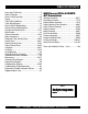
TABLE OF CONTENTS Here's How To Get Help .............................................3 Table Of Contents ......................................................4 Rules For Safe Operation ...................................... 6-9 Towing ......................................................................10 Trailer Safety Guidelines .................................... 11-17 Trailer Wiring Diagram..............................................18 Electric Brake Troubleshooting ...............................
PARTS ORDERING PROCEDURES ■ ■ ■ ■ ■ ■ ■ Dealer account number Dealer name and address Shipping address (if different than billing address) Return fax number Applicable model number Quantity, part number and description of each part Specify preferred method of shipment: • • • • UPS Ground UPS Second Day or Third Day* UPS Next Day* Federal Express Priority One (please provide us with your Federal Express account number)* • • Airborne Express* Truck or parcel post *Normally shipped the same day the order
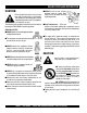
RULES FOR SAFE OPERATION CAUTION: Failure to follow instructions in this manual may lead to serious injury or even death! This equipment is to be operated by trained and qualified personnel only! This equipment is for industrial use only. The following safety guidelines should always be used when operating the DCA-400SPK portable generator: GENERAL SAFETY ■ DO NOT operate or service this equipment before reading this entire manual. ■ This equipment should not be operated by persons under 18 years of age.
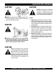
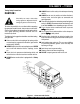
RULES FOR SAFE OPERATION CAUTION: CAUTION: DO NOT touch or open any of the below mentioned components while the generator is running. Always allow sufficient time for the engine and generator to cool before performing maintenance. ■ NEVER touch output terminals during operation. This is extremely dangerous. Always stop the machine when contact with the output terminals. CAUTION: Radiator 1.
RULES FOR SAFE OPERATION Battery CAUTION: Never over fill the battery with water above the upper limit. The battery contains acids that can cause injury to the eyes and skin. To avoid eye irritation, always wear safety glasses. Use well insulated gloves when picking up the battery. Use the following guidelines when handling the battery: 1. DO NOT drop the battery. There is the possibility of risk that the battery may explode. ■ NEVER Run engine without air filter. Severe engine damage may occur.
RULES FOR SAFE OPERATION Transporting ■ Always shutdown engine before transporting. ■ Tighten fuel tank cap securely. ■ Drain fuel when transporting generator over long distances or bad roads. ■ Always tie-down the generator during transportation by securing the generator. ■ If generator is mounted on a trailer, make sure trailer complies with all local and state safety transportation laws. See page 10 for basic towing procedures.
DCA-400SPK — TOWING Towing Safety Precautions CAUTION : Check with your county or state safety towing regulations department before towing your generator. Vehicle towing To reduce the possibility of an accident while transporting the generator on public roads, always make sure the trailer (Figure 1) that supports the generator and the towing vehicle are in good operating condition and both units are mechanically sound.
DCA-400SPK — TRAILER-SAFETY GUIDELINES CAUTION: ALWAYS make sure the trailer is in good operating condition. Check the tires for proper inflation and wear. Also check the wheel lug nuts for proper tightness. Explanation of Chart: This section is intended to provide the user with trailer service and maintenance information. The service and maintenance guidelines referenced in this section apply a wide range of trailers.
DCA-400SPK — TRAILER-SPECIFICATIONS Table 1. Specifications MODEL APPLICATION FU E L C E LL BRAKE SYSTEM GVWR FRAME LENGTH FRAME WIDTH JACK STAND TRLR-10W SDW225, SGW250,TLW300 NO NO 1900LB S 96" 50" 800LB . FULL TILT WHEEL TRLR-10 DCA10, TLG12, DCA-15 NO NO 1900LB S 96" 50" 800LB . FULL TILT WHEEL TRLR-10XF DCA10, TLG-12, DCA15, TLW-300 52 GAL NO 1900LB S 96" 50" 800LB . FULL TILT WHEEL TRLR-225W WELDERS, D A 7000S S NO NO 2200LB S 85" 42" 800LB .
DCA-400SPK — TRAILER-SPECIFICATIONS Table 1. Specifications (Con't) MODEL COUPLER TIRES WHEELS AXLE HUBS SUSPENSION ELECTRICAL TRLR-10W 2" B A LL C LA S S 2 ADJUSTABLE 175-13C 13"X4.50" 2200# 2X 2 5 LUG 3 LE A F 4 WIRE LOOM W/ 4 POLE FLAT TRLR-10 2" B A LL C LA S S 2 ADJUSTABLE 175-13C 13"X4.5" 2200#2X 2 5 LUG 3 LE A F 4 POLE FLAT TRLR-10XF 2" B A LL C LA S S 2 ADJUSTABLE 175-13C 13"X4.
DCA-400SPK — TRAILER SAFETY GUIDELINES Brakes If your trailer has a braking system, the brakes should be inspected the first 200 miles of operation. This will allow the brake shoes and drums to seat properly. After the first 200 mile interval, inspect the brakes every 3,000 miles. If driving over rough terrain, inspect the brakes more frequently. trailer being towed or under-adjusted brakes.
DCA-400SPK — TRAILER SAFETY GUIDELINES Figure 2. Electrical Brake Components Hydraulic/Air/Surge Brakes Hydraulic brakes (Figure 3) should not require any special attention with the exception of routine maintenance such as shoe and lining replacement. These brakes can be adjusted in the same manner as electric brakes. Brake lines should be periodically checked for cracks, kinks, or blockage.
DCA-400SPK — TRAILER SAFETY GUIDELINES Tires/Wheels/Lug Nuts Tires and wheels are a very impor tant and critical components of the trailer. When specifying or replacing the trailer wheels it is important the wheels, tires, and axle are properly matched. CAUTION: DO NOT attempt to repair or modify a wheel. DO NOT install in inner tube to correct a leak through the rim.
DCA-400SPK — TRAILER SAFETY GUIDELINES Table 3. Suspension Torque Requirements Item Torque (Ft.-Lbs.) 3/8" U-BOLT MIN-30 MAX-35 7/16" U-BOLT MIN-45 MAX-60 1/2" U-BOLT MIN-45 MAX-60 SHACKLE BOLT SPRING EYE BOLT SNUG FIT ONLY. PARTS MUST ROTATE FREELY. LOCKING NUTS OR COTTER PINS ARE PROVIDED TO RETAIN NUT-BOLT ASSEMBLY. SHOULDER TYPE MIN-30 MAX-50 SHACKLE BOLT Lug Nut Torque Requirements It is extremely important to apply and maintain proper wheel mounting torque on the trailer.
DCA-400SPK — TRAILER-WIRING DIAGRAM NOTE: LIGHTS ARE ORIENTED FROM THE DRIVER’S SEAT PAGE 18 — DCA-400SPK — PARTS AND OPERATION MANUAL— REV.
DCA-400SPK — TRAILER-BRAKE TROUBLESHOOTING Table 5. Electric B rake Troubleshooting Symptom Possible C ause Solution No Brakes or Intermi ttent Brakes Any open ci rcui ts or broken wi res? Fi nd and correct. Any short ci rcui ts? Fi nd and correct. Faulty controller? Test and correct. Any loose connecti ons? Fi nd and repai r. Ground wi re secure? Fi nd and secure. Grease or oi l on magnets or li ni ngs? C lean or replace. C onnecti ons corroded? C lean and correct cause of corrosi on.
DCA-400SPK — TRAILER-BRAKE TROUBLESHOOTING Table 6. Hydraulic Brake Troubleshooting Symptom Possible Cause Solution No Brakes Brake line broken or kinked? Repair or replace. Weak Brakes or Brakes Pull to One Side Brake lining glazed? Reburnish or replace. Trailer overloaded? Correct weight. Brake drums scored or grooved? Machine or replace. Tire pressure correct? Inflate all tires equally. Tires unmatched on the same axle? Match tires.
DCA-400SPK — OPERATION AND SAFETY DECALS Machine Safety Decals The DCA-400SPK generator is equipped with a number of safety decals. These decals are provided for operator safety and maintenance information. The illustration below and on the preceding pages shows the decals as they appear on the machine. Should any of these decals become unreadable, replacements can be obtained from your dealer. DCA-400SPK — PARTS AND OPERATION MANUAL — REV.
DCA-400SPK — OPERATION AND SAFETY DECALS PAGE 22 — DCA-400SPK — PARTS AND OPERATION MANUAL— REV.
DCA-400SPK — SPECIFICATIONS Table 7. Specifications Generator Specifications Model DCA-400SPK Type Revolving field, self ventilated, open protected type synchronous generator Armature Connection Star with Neutral Phase 3 Standby Output 440 KVA (352.0 KW) Prime Output 400 KVA (320.0 KW) Voltage 240V or 480V Frequency 60 Hz Speed 1800 rpm Power Factor 0.8 Aux. AC Power Single Phase, 60 Hz Voltage 120 V Output 4.8 KW (2.
DCA-400SPK — GENERAL INFORMATION DCA-400SPK FAMILIARIZATION Control Box Generator The “Control Box” is provided with the following: ator z Main Circuit Breaker 1060 amps The MQ Power Model DCA-400SPK is a 320 kW gener generator that is designed as a high quality portable (requires a trailer z Over-Current Relay for transport) power source for telecom sites, lighting z High Idle Adjust Trimmer facilities, power tools, submersible pumps and other industrial and construction machinery.
DCA-400SPK — GENERAL INFORMATION Engine The DCA-400SPK is powered by a 4 cycle, water cooled, turbocharged KOMATSU Model SA6D140-Adiesel engine. This engine is designed to meet every performance requirement for the generator. Reference Table 1, page 16 for engine specifications. In keeping with Multiquip's policy of constantly improving its products, the specifications quoted herein are subject to change without prior notice.
DCA-400SPK — MAJOR COMPONENTS Figure 6. Major Components PAGE 26 — DCA-400SPK — PARTS AND OPERATION MANUAL— REV.
NOTE PAGE DCA-400SPK — PARTS AND OPERATION MANUAL — REV.
DCA-400SPK — DIMENSIONS (TOP AND SIDE) Figure 7a. Dimensions PAGE 28 — DCA-400SPK — PARTS AND OPERATION MANUAL— REV.
DCA-400SPK — DIMENSIONS (FRONT AND REAR) Figure 7b. Dimensions DCA-400SPK — PARTS AND OPERATION MANUAL — REV.
DCA-400SPK — CONTROL PANEL Figure 8. Control Panel PAGE 30 — DCA-400SPK — PARTS AND OPERATION MANUAL— REV.
DCA-400SPK — CONTROL PANEL The definitions below describe the controls and functions of the DCA-400SPK " Control Panel " (Figure 8). 1. Pilot Lamp – Indicates that the generator is working properly. If the engine does not engage (start) by the third attempt, the engine will be shutdown by the MPEC's " Over Crank Protection" mode. If the engine engages at a speed (RPM's) that is not safe, the MPEC will shutdown the engine by initializing the "Over Speed Protection" mode. 2.
DCA-400SPK — ENGINE OPERATING PANEL Figure 10. Engine Operating Panel PAGE 32 — DCA-400SPK — PARTS AND OPERATION MANUAL— REV.
DCA-400SPK — ENGINE OPERATING PANEL The definitions below describe the controls and functions of 4. the DCA-400SPK " Engine Operating Panel "(Figure 10). 1. Throttle Handle - This handle controls the speed of the engine (low or high). 2. Tachometer – Indicates engine speed in RPM’s for 60 Hz operation. This meter should indicate 1800 RPM’s 5. when the rated load is applied. In addition a built in hour meter will record the number of operational hours that 6. the generator has been in use. 3.
DCA-400SPK — OUTPUT TERMINAL PANEL OVERVIEW OUTPUT TERMINAL FAMILIARIZATION The “Output Terminal Panel” is provided with the following: z Two 120V GFCI receptacles, 20 amp z Three 240/139V output receptacles, 50 amp z Two 120V input receptacles, 20 amp (optional) z 3 Load Circuit Breakers 265V @65 amps z 2 Load GFCI Circuit Breakers 265V@ 20amps Connecting Load Loads can be connected to the generator by the UVWO Lugs or the convenience receptacles. (See figure 13).
DCA-400SPK — OUTPUT TERMINAL PANEL OVERVIEW NOTE FIGURE 14. Output Terminal Panel Legs O and Ground are considered Bonded Grounds. DCA-400SPK — PARTS AND OPERATION MANUAL — REV.
DCA-400SPK — OUTPUT TERMINAL PANEL OVERVIEW Output Terminal Panel Available Voltages A wide range of voltages are available to supply load to many different applications. Voltages may be selected by using the voltage change-over board and how you hookup your hard wire connection to the generator. To obtain some of the voltages listed, fine adjustment with the Voltage Regulator on the control panel is necessary. See the table below (Table 8) for a list of available voltages the generator is able to supply.
DCA-400SPK — OUTPUT TERMINAL PANEL OVERVIEW How to read the output terminal gauges. The gauges and knobs on the control panel DO NOT effect the generator output in any fashion. They are there to simply help the operator observe how much power is being supplied produced at the UVWO legs. To read the output of the W-U legs, for example, place the AC Voltmeter Change-over switch to the W-U position and the AC ammeter Change -over Switch to the U or W position to read the output on the selected leg. FIGURE 15.
DCA-400SPK — OUTPUT TERMINAL PANEL OVERVIEW Voltage Change-over Board The voltage change-over board changes the available voltages of the output terminal panel UVWO lugs. The voltage change-over board is located on the control box behind the control panel. There are six (6) plates that can be set into two set positions to get six different voltages. Unless specified differently, the generator comes from the factory in the 240V position.
DCA-400SPK — OUTPUT TERMINAL PANEL OVERVIEW 480 Volt Set position The voltage change-over board 480V set position uses all 6 plates in 3 different connection places. There are 2 plates at every position (Every plate is used). See figure 23 below. Single Phase, 480 Volt The following connection, with the voltage change-over board set into the 480V set position (See Figure 23), can offer SINGLE PHASE power at 480V.
DCA-400SPK — INSTALLATION Outdoor Installation Install the generator in a location where it will not be exposed to rain or sunshine. Make sure the generator is on secure level ground so that it cannot slide or shift around. Also install the generator in a manner so that the exhaust will not be discharged in the direction of nearby homes. CAUTION : An electric shock may happen when vibrators are used.
DCA-400SPK — INSTALLATION Figure 27. Typical Generator Grounding Application DCA-400SPK — PARTS AND OPERATION MANUAL — REV.
DCA-400SPK — PRE-SETUP General Inspection Prior to Operation Circuit Breakers The DCA-400SPK generator has been thoroughly inspected and accepted prior to shipment from the factory. However, be sure to check for damaged parts or components, or loose nuts and bolts, which could have occurred in transit. To protect the generator from an overload, a 3-pole,1060 amp, main circuit breaker is provided to protect the UVW output terminals from overload.
DCA-400SPK — PRE-SETUP Lubrication Oil Fill the engine crankcase with lubricating oil through the filler hole, but do not overfill. Make sure the generator is level. With the dipstick inserted all the way, but without being screw into the filler hole, verify that the oil level is maintained between the two notches (Figure 28) on the dipstick. See Table 9 for proper selection of engine oil. Fuel Fill the fuel tank with clean and fresh diesel fuel. DO NOT fill the tank beyond capacity.
DCA-400SPK — PRE-SETUP CAUTION : When adding coolant or antifreeze to the radiator, do not remove the radiator cap until the unit has completely cooled. Day-to-day addition of coolant is done from the reserve tank. When adding coolant to the radiator, DO NOT remove the radiator cap until the unit has completely cooled. See Table 12 for engine, radiator, and reserve tank coolant capacities. Make sure the coolant level in the reserve tank is always between the "H" and the "L" markings. Table 12.
DCA-400SPK — PRE-SETUP Battery Cable Installation ALWAYS be sure the battery cables (Figure 30) are properly connected to the battery terminals as shown below. The RED cable is connected to the positive terminal of the battery, and the BLACK cable is connected to the negative terminal of the battery. CAUTION : Inadequate battery connections may cause poor starting of the generator, and create other malfunctions. Wiring Inspect the entire generator for bad or worn electrical wiring or connections.
DCA-400SPK — LOAD APPLICATION Single Phase Load CAUTION: Always be sure to check the nameplate on the generator and equipment to insure the wattage, amperage and frequency requirements are satisfactorily supplied by the generator for operating the equipment. Generally, the wattage listed on the nameplate of the equipment is its rated output.
DCA-400SPK — GENERATOR START-UP PROCEDURE (MANUAL) WARNING: Before Starting zThe engine's exhaust contains harmful W AY S ventilate the emissions. A LLW exhaust when operating inside tunnels, excavations or buildings. Direct exhaust away from nearby personnel. Engine 1. Check the lubricating oil level prior to starting the engine. Make sure the generator is level. The oil level must be maintained between two notches on the dipstick. 2.
DCA-400SPK — GENERATOR START-UP PROCEDURE (MANUAL) 2. Connect the load to the UVW terminals as shown in Figure 32. These terminals can be found on the output terminal panel, see page 35 Figure 14. To gain access to the output terminals lift the UVW cover. Make sure to tighten terminal nuts securely to prevent load wires from slipping out. 4. Close all engine enclosure doors (Figure 34). Figure 34. Engine Enclosure Doors 5. Set the battery ON/OFF switch (Figure 35) to the ON position. Figure 32.
DCA-400SPK — GENERATOR START-UP PROCEDURE (MANUAL) 7. Place the Off/Manual/Auto switch (Figure 38) in the MANUAL position (down). Observe that the engine begins to crank. Figure 41. Frequency Meter (Hz) Figure 38. Off/Manual/Auto Switch (Manual) 8. After engine starts, verify that the "Engine Running" status LED (Figure 39) on the Microprocessor Engine Control Module (MPEC) display is "ON" (lit). 11. The generator's voltage meter (Figure 42) displays the 120 VAC in VOLTS.
DCA-400SPK — GENERATOR START-UP PROCEDURE (MANUAL) 13. The engine oil pressure gauge (Figure 45) will indicate the oil pressure (kg/ cm2) of the engine. Under normal operating conditions the oil pressure should be approximately 25 psi. 16. Turn the MAIN, GFCI and LOAD circuit breakers to their "ON" position (Figure 48). Figure 48. Main and GFCI Circuit Breakers Figure 45. Oil Pressure Gauge 14. The coolant temperature gauge (Figure 46) will indicate the coolant temperature.
DCA-400SPK — GENERATOR START-UP PROCEDURE (AUTO) CAUTION: Before connecting this generator to any building’s electrical system, a licensed electrician must install an isolation (transfer) switch. Serious injury or death may result without this transfer switch. CAUTION: When connecting the generator to a isolation (transfer) switch, ALWAYS have power applied to the generator's internal battery charger. This will ensure that the engine will not fail due to a dead battery.
DCA-400SPK — GENERATOR SHUTDOWN PROCEDURE Engine Shutdown To shutdown the generator use the following procedure: 1. Place both the MAIN, GFCI and LOAD circuit breakers to the "OFF position". 2. Let the engine cool by running it for 3-5 minutes with no load applied. Emergency Stop 1. To stop the engine in the event of an emergency, PUSH the emergency stop button ( Figure 53) inward.This button is located on the generator's engine operating panel, see page 30, Figure 11. 3.
NOTE PAGE DCA-400SPK — PARTS AND OPERATION MANUAL — REV.
DCA-400SPK — MAINTENANCE General Inspection Prior to each use, the generating set should be cleaned and inspected for deficiencies. Check for loose, missing or damaged nuts, bolts or other fasteners. Also check for fuel or oil leaks. Air Cleaner Every 50 hours: If dust indicator is red, clean the air cleaner element. Outer Element: 1. Loosen wing bolt, remove dust cup, then remove wing nut and take out element. 2. Clean the inside of the body and cover using a damp cloth. 3. Blow dry with compressed air (0.
DCA-400SPK — MAINTENANCE 5. When the water level is near the mouth of the water filler, open drain plugs and start the engine, and run at low idling. Keep the engine running at low idling and flush the radiator for about 10 minutes. 6. Adjust the flow of the water flowing in and draining out to ensure that the radiator is always full during the flushing operation, While flushing water through the system, watch carefully the water inlet hose does not come out of the radiator filler port. 7.
DCA-400SPK — MAINTENANCE 7. After bleeding the air, tighten air bleed plug, then push in the knob of feed pump and lock it in position. 8. Replace Corrosion resistor cartridge (if equipped) 9. Screw in valves at the top of the corrosion resistor. 10. Using a filter wrench, turn the cartridge to the left to remove it. 11. Coat the seal surface of the new cartridge with engine oil and install it to the filter holder. 12.
DCA-400SPK — MAINTENANCE TABLE 15.
DCA-400SPK — GENERATOR WIRING DIAGRAM PAGE 58 — DCA-400SPK — PARTS AND OPERATION MANUAL— REV.
NOTE PAGE DCA-400SPK — PARTS AND OPERATION MANUAL — REV.
DCA-400SPK — ENGINE WIRING DIAGRAM PAGE 60 — DCA-400SPK — PARTS AND OPERATION MANUAL— REV.
DCA-400SPK — ENGINE WIRING DIAGRAM (MPEC) DCA-400SPK — PARTS AND OPERATION MANUAL — REV.
DCA-400SPK — TROUBLESHOOTING (ENGINE) Practically all breakdowns can be prevented by proper handling and maintenance inspections, but in the event of a breakdown, use the tables shown for diagnosis based on the Engine Troubleshooting (Table 16). If the problem cannot be remedied, consult our company's business office or service plant. TAB LE 16. EN GIN E TR OU B LESH OOTIN G SYMPTOM Engi ne does not start. POSSIB LE PR OB LEM SOLU TION No fuel? Repleni sh fuel.
DCA-400SPK — TROUBLESHOOTING (ENGINE) TABLE 16. ENGINE TROUBLESHOOTING (CONTINUED) SYMPTOM Engine revolution is not smooth. Either white or blue exhaust gas is observed. Either black or dark gray exhaust gas is observed. Deficient output. POSSIBLE PROBLEM SOLUTION Fuel filter clogged or dirty? Clean or change. Air cleaner clogged? Clean or change. Fuel leak due to loose injection pipe retaining nut? Tighten nut. Injection pump malfunctioning? Repair or replace.
DCA-400SPK — TROUBLESHOOTING (GENERATOR/ENGINE) Practically all breakdowns can be prevented by proper diagnosis based on the Engine and Radiator Troubleshooting handling and maintenance inspections, but in the event of a (Table 17). If the problem cannot be remedied, consult our breakdown, use the tables shown for company's business office or service plant. TABLE 17. GENERATOR TROUBLESHOOTING SYMPTOM POSSIBLE PROBLEM SOLUTION AC Voltmeter defective? Check output voltage using a voltmeter.
DCA-400SPK — TROUBLESHOOTING (MPEC) TAB LE 18. MPEC TR OU B LESH OOTIN G Sympton Low oi l pressure li ght i s on. Low coolant level li ght i s on. Hi gh coolant temperture li ght i s on. Overcrank li ght i s on. Overspeed li ght i s on. Loss of MPU li ght(s) or on. Possible C ause Solution Low oi l level? Fi ll oi l level. Oi l pressure sendi ng uni t fai lure? Replace oi l pressure sendi ng uni t. Ti me delay malfunti on i n MPEC ? Refer to dealer. Wi re shorted? Inspect/repai r wi re.
EXPLANATION OF CODE IN REMARKS COLUMN How to read the marks and remarks used in this parts book. Items Found In the “Remarks” Column Serial Numbers-Where indicated, this indicates a serial number range (inclusive) where a particular part is used. Model Number-Where indicated, this shows that the corresponding part is utilized only with this specific model number or model number variant.
DCA-400SPK — SUGGESTED SPARE PARTS DCA-400SPK W/K OMA TSU SA6D140E-2 W/KOMA OMATSU DIESEL ENGINE 1 to 5 Units Qty. P/N Description 10 .....6125817051 ... AIR FILTER 10 .....6003117111 ... FUEL FILTER 10 .....6002111231 ... OIL FILTER 5 ....... 6004111171 ... CARTRIDGE, CORROSION RESISTOR 1 ....... 0601804887 ... CIRCUIT BREAKER 1 ....... 0601810575 ... PILOT LAMP, ENGINE TROUBLE 1 ....... 0601810576 ... PILOT LAMP, ENGINE TROUBLE 1 ....... 0412122258 ... ENGINE FAN BELT 1 ....... 6008155390 ...
DCA-400SPK GENERATOR ASSY. GENERATOR ASSY. PAGE 68 — DCA-400SPK — PARTS AND OPERATION MANUAL— REV.
DCA-400SPK GENERATOR ASSY. GENERATOR ASSY. NO. 1 1-1 1-2 1-3 1-4 1-5 1-6 1-7 1-8 1-9 1-10 1-11 1-12 1-13 1-14 1-15 1-16 1-17 1-18 1-19 2 3 4 5 5-1 6 6-1 7 7-1 8 9 10 10-1 10-2 11 12 13 14 15 16 17 18 19 PART NO.
DCA-400SPK GENERATOR ASSY. GENERATOR ASSY. PAGE 70 — DCA-400SPK — PARTS AND OPERATION MANUAL— REV.
DCA-400SPK GENERATOR ASSY. GENERATOR ASSY. NO. 20 21 22 23 24 25 26 27 28 29 30 31 32 33 34 35 36 PART NO. 0041212000 8201310014 8201312014 0010106065 0040006000 0041206000 8171331013 0017106012 8171333003 0010106030 0040006000 0041206000 0012112035 0042512000 8201332003 0605000012 0030020000 0040020000 PART NAME PLAIN WASHER COVER, BEARING GASKET, BEARING HEX. HEAD BOLT LOCK WASHER PLAIN WASHER COVER, END BRACKET HEX. HEAD BOLT COVER, END BRACKET HEX. HEAD BOLT LOCK WASHER PLAIN WASHER HEX.
DCA-400SPK CONTROL BOX ASSY. CONTROL BOX ASSY. PAGE 72 — DCA-400SPK — PARTS AND OPERATION MANUAL— REV.
DCA-400SPK CONTROL BOX ASSY. CONTROL BOX ASSY. NO 1 2 3 4 4-1 5 6 7 8 9 10 11 12 13 14 15 16 17 18 19 20 21 22 23 24 25 26 27 28 29 PART NO PART NAME QTY.
DCA-400SPK CONTROL BOX ASSY. CONTROL BOX ASSY. PAGE 74 — DCA-400SPK — PARTS AND OPERATION MANUAL— REV.
DCA-400SPK CONTROL BOX ASSY. CONTROL BOX ASSY. NO 30 31 32 33 34 35 36 37 38 39 40 41 42 43 44 45 46 47 48 49 50 51 52 53 54 PART NO PART NAME QTY.
DCA-400SPK ENGINE & RADIATOR ASSY. ENGINE & RADIATOR ASSY. PAGE 76 — DCA-400SPK — PARTS AND OPERATION MANUAL— REV.
DCA-400SPK ENGINE & RADIATOR ASSY. ENGINE & RADIATOR ASSY. NO. 1 2 3 4 5 6 7 8 9 10 11 12 13 14 15 16 17 18 19 20 21 22 23 24 25 26 27 28 29 30 31 32 PART NO.
DCA-400SPK ENGINE & RADIATOR ASSY. ENGINE & RADIATOR ASSY. PAGE 78 — DCA-400SPK — PARTS AND OPERATION MANUAL— REV.
DCA-400SPK ENGINE & RADIATOR ASSY. ENGINE & RADIATOR ASSY. NO. 33 34 35 36 37 38 39 40 41 42 43 44 45 46 47 48 49 PART NO. 0602010900 8212082103 0229200600 0017106025 0017108020 0199601150 0193601300 0605515024 0194700400 0194700450 0198501050 3972220103 0017110025 8212256104 0019208020 8212044103 0017110025 PART NAME CAP, RESERVE TANK BRACKET, RESERVE TANK RUBBER CUSHION HEX. HEAD BOLT HEX. HEAD BOLT HOSE HOSE HOSE BAND HOSE HOSE HOSE SUPPORT ROD HEX. HEAD BOLT SUPPORT ROD HEX. HEAD BOLT OIL PANEL HEX.
DCA-400SSKENGINE OPERATING PANEL ASSY. ENGINE OPERATING PANEL ASSY. PAGE 80 — DCA-400SPK — PARTS AND OPERATION MANUAL— REV.
DCA-400SPK ENGINE OPERATING PANEL ASSY. ENGINE OPERATING PANEL ASSY.
DCA-400SSKENGINE OPERATING PANEL ASSY. ENGINE OPERATING PANEL ASSY. PAGE 82 — DCA-400SPK — PARTS AND OPERATION MANUAL— REV.
DCA-400SPK ENGINE OPERATING PANEL ASSY. ENGINE OPERATING PANEL ASSY. NO 40 41 42 43 44 45 46 47 47-1 48 49 50 51 52 53 54 55 PART NO 0041420000 3501860604 0019110040 0042310000 0042410000 0601812597 0601811034 0601805313 0601805840 8211834203 0223300200 0019106035 0042306000 0042406000 8215082003 0019112045 0042412000 0805009804 0205012000 0845043704 0019208020 PART NAME PLAIN WASHER TERMINAL PLATE HEX. HEAD BOLT LOCK WASHER PLAIN WASHER RECEPTACLE, AUX. POWER RECEPTACLE, AUX.
DCA-400SPK — BATTERY ASSY. BATTERY ASSY. PAGE 84 — DCA-400SPK — PARTS AND OPERATION MANUAL— REV.
DCA-400SPK — BATTERY ASSY. BATTERY ASSY. NO. 1 2 3 4 5 6 7 8 9 10 11 12 13 14 15 16 17 18 19 PART NO. 0168719052 0805018904 0805006404 0805006504 0037808000 0040008000 0041208000 8212265304 8212265104 6212265504 8212265704 8212265904 0010010030 0030010000 0845040114 0845041004 0845040214 0845041104 0602220205 PART NAME BATTERY BATTERY SHEET BATTERY BAND BATTERY BOLT WING NUT LOCK WASHER PLAIN WASHER BATTERY CABLE BATTERY CABLE BATTERY CABLE BATTERY CABLE EARTH CABLE HEX. HEAD BOLT HEX.
DCA-400SPK — MUFFLER ASSY. MUFFLER ASSY. PAGE 86 — DCA-400SPK — PARTS AND OPERATION MANUAL— REV.
DCA-400SPK — MUFFLER ASSY. MUFFLER ASSY. NO. 1 2 3 4 5 6 7 8 9 10 11 11-1 12 13 14 15 16 17 18 19 20 21 22 PART NO. 8212311002 0019112025 0042312000 0042412000 8212356004 8222356104 8222356204 0019110030 0042310000 0042410000 8212350003 0602320095 0010312060 0010312030 0030312000 0040012000 0041212000 8212355003 7432356104 0019112050 0030012000 0042312000 0042412000 PART NAME MUFFLER HEX. HEAD BOLT LOCK WASHER PLAIN WASHER PACKING PACKING PACKING HEX.
DCA-400SPK — FUEL TANK ASSY. FUEL TANK ASSY. PAGE 88 — DCA-400SPK — PARTS AND OPERATION MANUAL— REV.
DCA-400SPK — FUEL TANK ASSY. FUEL TANK ASSY. NO. 1 1-1 1-2 1-3 1-4 2 3 4 5 6 7 8 9 10 11 12 13 14 15 16 17 18 PART NO. 8215510503 0845500104 0810105400 0264100390 0605515079 8225523104 0805003414 0017108020 0037908000 0222100300 0130206000 3515512014 0603325011 0132006000 0191302290 0191302390 0191003750 0605515014 0605515024 0605503020 0802120604 0845039604 PART NAME FUEL TANK CAP, FUEL TANK FUEL FILTER HOSE, FUEL GAUGE HOSE BAND TANK BAND PAD, TANK BAND HEX. HEAD BOLT HEX.
DCA-400SPK — ENCLOSURE ASSY. ENCLOSURE ASSY. PAGE 90 — DCA-400SPK — PARTS AND OPERATION MANUAL— REV.
DCA-400SPK — ENCLOSURE ASSY. ENCLOSURE ASSY. NO. 1 2 3 4 5 6 7 8 9 10 11 12 13 14 15 16 17 18 19 PART NO. 8215111022 3515116114 8215116004 0019208020 8215020204 8215102003 0019110025 0042310000 0042410000 8225125104 8225125204 8225102104 0019208020 0845042703 0019208020 8215125003 0019208020 8215131202 0010120070 0030020000 0040020000 0041220000 0010120060 0030020000 0040020000 0041220000 8215041414 8215940304 8225151004 0207006000 PART NAME BASE FLOOR PANEL FLOOR PANEL HEX.
DCA-400SPK — ENCLOSURE ASSY. ENCLOSURE ASSY. PAGE 92 — DCA-400SPK — PARTS AND OPERATION MANUAL— REV.
DCA-400SPK — ENCLOSURE ASSY. ENCLOSURE ASSY. NO. 20 21 22 23 24 25 26 27 28 29 30 31 32 33 34 35 36 37 38 39 40 41 42 43 PART NO. 0019110025 0042310000 0042410000 8215155203 8215946304 8195151204 0207006000 0019208020 8215155104 8215102804 0017108020 8215143503 8225143403 8225147004 0037906000 0845050804 0845052404 0021806016 8225146204 8225146304 0845050704 0207006000 0805011304 0805011204 0207006000 0845047104 0845045004 0845047204 0845045004 0019208020 8215161002 PART NAME HEX.
DCA-400SPK — ENCLOSURE ASSY. ENCLOSURE ASSY. PAGE 94 — DCA-400SPK — PARTS AND OPERATION MANUAL— REV.
DCA-400SPK — ENCLOSURE ASSY. ENCLOSURE ASSY. NO. 44 45 46 47 48 49 50 51 52 53 54 55 56 57 58 59 PART NO.
DCA-400SPK — ENCLOSURE ASSY. ENCLOSURE ASSY. PAGE 96 — DCA-400SPK — PARTS AND OPERATION MANUAL— REV.
DCA-400SPK — ENCLOSURE ASSY. ENCLOSURE ASSY. NO. PART NO. PART NAME 60 61 62 63 8195151004 8215151004 0207006000 8215176004 8215974504 8215176204 8215103404 0017108020 0825007362 0605010225 0021806016 0845046904 0845045004 0845047004 0845045004 0019208020 0601850097 0021008025 0845031504 8215312002 0017110030 0010110030 0030010000 0040010000 0041210000 6360510003 0021106020 LOUVER PANEL LOUVER PANEL HEX. NUT DUCT LINING DUCT LINING HEX.
DCA-400SPK — RUBBER SEAL ASSY. PAGE 98 — DCA-400SPK — PARTS AND OPERATION MANUAL— REV.
DCA-400SPK — RUBBER SEAL ASSY. RUBBER SEAL ASSY. NO. 79 80 81 82 83 84 85 86 87 88 89 PART NO. 0228901450 0228901390 0228900795 0228900850 0229201440 0229201440 0228800795 0228801240 0229201340 0228100120 0228100510 PART NAME RUBBER SEAL RUBBER SEAL RUBBER SEAL RUBBER SEAL RUBBER SEAL RUBBER SEAL RUBBER SEAL RUBBER SEAL RUBBER SEAL RUBBER SEAL RUBBER SEAL QTY. 3 3 8 1 1 2 2 2 1 4 4 REMARKS DCA-400SPK — PARTS AND OPERATION MANUAL — REV.
DCA-400SPK — OIL PIPING ASSY. OIL PIPING ASSY. PAGE 100 — DCA-400SPK — PARTS AND OPERATION MANUAL— REV.
DCA-400SPK — OIL PIPING ASSY. OIL PIPING ASSY. NO. 1 2 3 4 5 6 7 8 9 10 11 12 13 14 PART NO. 0602023040 8215191013 0017106025 0017110030 7522054204 0131506000 0120006005 3972027104 3972054104 3972054304 0265801650 0605515003 0193301200 0605515004 PART NAME PUMP BRACKET, PUMP HEX. HEAD BOLT HEX. HEAD BOLT BUSHING NIPPLE VALVE HOSE JOINT HOSE JOINT PACKING HOSE HOSE BAND HOSE HOSE BAND QTY. 1 1 5 4 1 1 1 1 1 1 1 2 1 1 REMARKS DCA-400SPK — PARTS AND OPERATION MANUAL — REV.
DCA-400SPK — NAME PLATE AND DECALS NAME PLATE AND DECALS CONTROL BOX GROUP ENGINE OPERATING PANEL GROUP PAGE 102 — DCA-400SPK — PARTS AND OPERATION MANUAL— REV.
DCA-400SPK — NAME PLATE AND DECALS NAME PLATE ASSY. NO. PART NO. 2-1 2-2 2-3 2-4 2-5 2-6 2-7 2-8 2-9 2-10 2-11 0800520100 0800520904 0800520814 0840624504 0840624604 0840624704 0840624804 B9531100604 C0551000903 C2551000004 C3561101103 PART NAME QTY. REMARKS CONTROL BOX GROUP PLATE: ON-OFF .............................................. 1 ......... AT-202 PLATE: AMMETER CHNG.-OVER SWTH. ..... 1 ......... N-2438 PLATE: VOLTMETER CHNG.-OVER SWTH. .. 1 ......... N-2439 DECAL: CIRCUIT BREAKER ...............
DCA-400SPK — NAME PLATE AND DECALS NAME PLATE AND DECALS BONNET GROUP BATTERY GROUP ENGINE AND RADIATOR GROUP PAGE 104 — DCA-400SPK — PARTS AND OPERATION MANUAL— REV.
DCA-400SPK — NAME PLATE AND DECALS NAME PLATE ASSY. NO. PART NO. PART NAME 3-1 3-2 3-3 6360610304 B9504000404 B9504100104 ENGINE & RADIATOR GROUP DECAL: WATER ............................................... 1 ......... S-1880 DECAL: WARNING .......................................... 2 ......... B90400040 DECAL: WARNING .......................................... 1 .........
TERMS AND CONDITIONS OF SALE — PARTS Effective: July 1, 2000 PAYMENT TERMS 4. Terms of payment for parts are net 10 days. FREIGHT POLICY All parts orders will be shipped collect or prepaid with the charges added to the invoice. All shipments are F.O.B. point of origin. Multiquip’s responsibility ceases when a signed manifest has been obtained from the carrier, and any claim for shortage or damage must be settled between the consignee and the carrier. Freight is at the sender’s expense.
NOTE PAGE DCA-400SPK — PARTS AND OPERATION MANUAL — REV.
PARTS AND OPERATION MANUAL HERE'S HOW TO GET HELP PLEASE HAVE THE MODEL AND SERIAL NUMBER ON-HAND WHEN CALLING PAR TS DEP AR TMENT ARTS DEPAR ARTMENT 800/427-1244 or 310/537-3700 FAX: 800/672-7877 or 310/637-3284 VICE DEP AR TMENT SER ARTMENT SERVICE DEPAR 800/835-2551 or 310/537-3700 FAX: 310/638-8046 WARRANTY DEP AR TMENT DEPAR ARTMENT 800/835-2551 or 310/537-3700 FAX: 310/638-8046 MAIN 800/421-1244 or 310/537-3700 FAX: 310/537-3927 Manufactured for Multiquip Inc. by DENYO MANUFACTURING, CO.