PARTS AND OPERATION MANUAL OPERATION AND PARTS MANUAL WHISPERWATTTM SERIES MODEL DCA-180SSV 60 Hz GENERATOR PARTS LIST NO. C0870301204 Serial Number 3770213~ Revision #1 (04/14/10) THIS MANUAL MUST ACCOMPANY THE EQUIPMENT AT ALL TIMES.
Diesel engine exhaust and some of PAGE 2 — DCA-180SSV— OPERATION AND PARTS MANUAL — REV.
1 DCA-180SSV— OPERATION AND PARTS MANUAL — REV.
TABLE OF CONTENTS MQ POWER DCA-180SSV WHISPER WATTTM GENERATOR WHISPERW California Proposition 65 Warning ..................................... 2 Here's How To Get Help .................................................... 3 Table Of Contents ............................................................. 4 Parts Ordering Procedures ............................................... 5 Specifications ................................................................... 6 Dimensions (Top, Side, Front) ...............
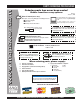
www.mqpower.com PARTS ORDERING PROCEDURES Ordering parts has never been easier! Choose from three easy options: Order via Internet (Dealers Only): Best Deal! Effective: January 1st, 2006 If you have an MQ Account, to obtain a Username and Password, E-mail us at: parts@multiquip. com. Order parts on-line using Multiquip’s SmartEquip website! N View Parts Diagrams N Order Parts N Print Specification Information To obtain an MQ Account, contact your District Sales Manager for more information.
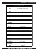
DCA-180SSV— SPECIFICATIONS Table 1. Generator Specifications Model DCA-180SSV Type Revolving field, self ventilated, open protected type synchronous generator Armature Connection Star with Neutral Phase 3 Standby Output 198 KVA (158 KW) Prime Output 180 KVA (144 KW) Voltage — 1Ø 120, 127, 139, 240, 254, and 277V Voltage — 3Ø 208, 220, 240, 416, 440, and 480V Frequency 60 Hz Speed 1800 rpm Power Factor 0.8 Aux. AC Power Single Phase, 60 Hz Aux. Voltage/Output 120 VAC/ 4.8 Kw (2.
DCA-180SSV— DIMENSIONS (TOP, SIDE AND FRONT) Figure 1. Dimensions TABLE 3. DIMENSIONS Reference Letter Dimension in. (mm.) Reference Letter Dimension in. (mm.) A 37.00 in. (940 mm.) F 139.7 in. (3,550 mm.) B 37.00 in. (940 mm.) G 70.98 in. (1,800 mm.) C 41.33 in. (1,050 mm.) H 47.24 in. (1,200 mm.) D 41.33 in. (1,050 mm.) E 41.33 in. (1,050 mm.) 1 DCA-180SSV— OPERATION AND PARTS MANUAL — REV.
DCA-180SSV— SAFETY MESSAGE ALERT SYMBOLS FOR YOUR SAFETY AND THE SAFETY OF OTHERS! Safety precautions should be followed at all times when operating this equipment. Failure to read and understand the Safety Messages and Operating Instructions could result in injury to yourself and others. NOTE This Owner's Manual has been developed to provide complete instructions for the safe and efficient operation of the MQ Power Model DCA-180SSV Whisperwatt™ Generator.
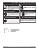
DCA-180SSV— SAFETY MESSAGE ALERT SYMBOLS WARNING - ROTATING PARTS NEVER operate equipment with covers, or guards removed. Keep fingers, hands, hair and clothing away from all moving parts to prevent injury. CAUTION - ACCIDENTAL STARTING ALWAYS place the Engine ON/OFF switch in the OFF position and remove the ignition key when the pump is not in use. CAUTION - OVER-SPEED CONDITIONS NEVER tamper with the factory settings of the engine governor or settings.
DCA-180SSV— RULES FOR SAFE OPERATION DANGER - READ THIS MANUAL! Failure to follow instructions in this manual may lead to serious injury or even DEATH! This equipment is to be operated by trained and qualified personnel only! This equipment is for industrial use only. The following safety guidelines should always be used when operating the DCA-180SSVWhisperwatt™ AC Generator. General Safety: ■ DO NOT operate or service this equipment before reading this entire manual.
DCA-180SSV— RULES FOR SAFE OPERATION Generator Grounding To guard against electrical shock and possible damage to the equipment, it is important to provide a good EARTH ground. Article 250 (Grounding) of the National Electrical Code (NEC) provides guide lines for proper grounding and specifies that the cable ground shall be connected to the grounding system of the building as close to the point of cable entry as practical.
DCA-180SSV— RULES FOR SAFE OPERATION Maintenance Safety ■ The electrical voltage required to operate the generator can cause severe injury or even death through physical contact with live circuits. Turn all circuit breakers OFF before performing maintenance on the generator. ■ NEVER lubricate components or attempt service on a running machine. ■ ALWAYS disconnect the NEGATIVE battery terminal before performing service on the generator.
DCA-180SSV— RULES FOR SAFE OPERATION Towing & Transporting Safety ■ The maximum speed for highway towing is 55 MPH unless posted otherwise. Recommended off-road towing To reduce the possibility of an accident while transporting is not to exceed 15 MPH or less depending on type of the generator on public roads, always make sure the trailer terrain.
DCA-180SSV— GENERATOR DECALS The DCA-180SSVgenerator is equipped with a number of safety decals (Figures 2 & 3). These decals are provided for operator safety and maintenance information. The illustration below and on the preceding page show the decals as they appear on the machine. Should any of these decals become unreadable, replacements can be obtained from your dealer. Figure 2. Generator Decals PAGE 14 — DCA-180SSV— OPERATION AND PARTS MANUAL — REV.
DCA-180SSV— GENERATOR DECALS Figure 3. Generator Decals (Cont inued) DCA-180SSV— OPERATION AND PARTS MANUAL — REV.
DCA-180SSV— INSTALLATION Figure 4. Typical Generator Grounding Application PAGE 16 — DCA-180SSV— OPERATION AND PARTS MANUAL — REV.
DCA-180SSV— INSTALLATION Outdoor Installation Generator Grounding Install the generator in a area that is free of debris, bystanders, and overhead obstructions. Make sure the generator is on secure level ground so that it cannot slide or shift around. Also install the generator in a manner so that the exhaust will not be discharged in the direction of nearby homes. The installation site must be relatively free from moisture and dust. All electrical equipment should be protected from excessive moisture.
DCA-180SSV— GENERAL INFORMATION DCA-180SSVWhisperwatt™ Series Familiarization Generator The MQ Power Model DCA-180SSVis a 158 kW generator (Figure 5) that is designed as a high quality portable (requires a trailer for transport) power source for telecom sites, lighting facilities, power tools, submersible pumps and other industrial and construction machinery.
DCA-180SSV— MAJOR COMPONENTS Table 4. Generator Major Components ITEM NO. DESCRIPTION 1 Muffler Assembly 2 Air Filter Assembly 3 Generator Assembly 4 Output Terminal Panel Assembly 5 Battery Assembly 6 Output Receptacles Assembly 7 Engine and Radiator Assembly 8 Fuel Tank Assembly 9 Circuit Breaker Assembly 10 Engine Operatingl Panel Assembly 11 Generator Control Panel Assembly Figure 5. Major Components DCA-180SSV— OPERATION AND PARTS MANUAL — REV.
NOTE PAGE PAGE 20 — DCA-180SSV— OPERATION AND PARTS MANUAL — REV.
DCA-180SSV— GENERATOR CONTROL PANEL Figure 6. Generator Control Panel The definitions below describe the controls and functions of Located behind the generator control panel is the Generator the DCA-180SSVU Generator Control Panel (Figure 6). Control Box. This box contains some of the necessary 1. Frequency Meter – Indicates the output frequency in electronic components required to make the generator function. hertz (Hz). Normally 60 Hz. 2.
DCA-180SSV— ENGINE OPERATING PANEL Figure 7. Engine Operating Panel PAGE 22 — DCA-180SSV— OPERATION AND PARTS MANUAL — REV.
DCA-180SSV— ENGINE OPERATING PANEL The definitions below describe the controls and functions of the DCA-220SSVU Engine Operating Panel (Figure 7). 1. Panel Light – Normally used in dark areas or at night time. When activated, panel lights will illuminate. When the generator is not in use be sure to turn the panel light switch to the OFF position. 2. Panel Light Switch – When activated will turn on control panel light. 3.
DCA-180SSV— OUTPUT TERMINAL PANEL FAMILIARIZATION Output Terminal Panel The Output Terminal Panel (Figure 8) shown below is located on the right-hand side (left from control panel) of the generator. Lift up on the cover to gain access to receptacles and terminal lugs.
DCA-180SSV— OUTPUT TERMINAL PANEL FAMILIARIZATION 120 VAC GFCI Receptacles There are two 120 VAC, 20 amp GFCI (Duplex Nema 5-20R) recepacles provided on the output terminal panel. These receptacles can be accessed in any voltage selector switch position. Each receptacle is protected by a 20 amp circuit breaker. These breakers are located directly above the GFCI receptacles.
DCA-180SSV— OUTPUT TERMINAL PANEL FAMILIARIZATION Connecting Loads Loads can be connected to the generator by the Ouput Terminal Lugs or the convienience receptacles (Figure 12). Make sure to read the operation manual before attempting to connect a load to the generator. To protect the output terminals from overload, a 3-pole, 1000A main circuit breaker is provided. Make sure to switch ALL circuit breakers to the OFF position prior to starting the engine.
DCA-180SSV— LOAD APPLICATION Single Phase Load Three Phase Load Always be sure to check the nameplate on the generator and equipment to insure the wattage, amperage, frequency, and voltage requirements are satisfactorily supplied by the generator for operating the equipment. When calculating the power requirements for 3-phase power use the following equation: Generally, the wattage listed on the nameplate of the equipment is its rated output.
DCA-180SSV — GENERATOR OUTPUTS Generator Amperage Generator Output Voltages A wide range of voltages are available to supply voltage for Tables 8 and 9 describe the generator’s current output capamany different applications. Voltages are selected by apply- bility for both 1Ø-phase and 3Ø phase applications. ing jumpers (6) to the voltage change-over board (Figure 14). To obtain some of the voltages as listed in Table 6 (see Table 8.
DCA-180SSV— GENERATOR OUTPUTS/ GAUGE READING Maximum Amps Table 10 shows the maximum amps the generator can provide. DO NOT exceed the maximum amps as listed. Table 10. Generator Maximum Amps Model DCA220SSVU Rated Voltage Maximum Amps Single Phase 120 Volt 400 amps (4 wire) Single Phase 240 Volt 200 amps (4 wire) Three Phase 240 Volt 433 amps Three Phase 480 Volt 216 amps How to Read the Output Terminal Gauge.
DCA-180SSV— OUTPUT TERMINAL PANEL CONNECTIONS UVWO Terminal Output Voltages Various output voltages can be obtained using the UVWO output terminal lugs. The voltages at the terminals are dependent on the placement of the jumpers plates (6) on the Voltage Change-Over Board and the adjustment of the Figure 22. Voltage Regulator Knob Voltage Regulator Control Knob.
DCA-180SSV— OUTPUT TERMINAL PANEL CONNECTIONS 3Ø-480V UVWO Terminal Output Voltages 1Ø-480V UVWO Terminal Output Voltages 1. Jumper the voltage change-over board for 480V operation 1. Make sure the voltage change-over board is jumpered as shown in Figure 25. This configuration uses 6 jumper for 480V operation as shown in Figure 25. plates in 3 different positions. Remember there are 2 2. Connect the load wires to the UVWO terminals as shown jumper plates at every position.
DCA-180SSV— SETUP Fuel Check Circuit Breakers To protect the generator from an overload, a 3-pole, 600 amp, main circuit breaker is provided to protect the U,V, and W Output Terminals from overload. In addition two single-pole, 20 amp GFCI circuit breakers are provided to protect the GFCI receptacles from overload. Three 50 amp load circuit breakers have also been provided to protect the auxiliary receptacles from overload.
DCA-180SSV— SETUP Refueling Procedure: 3. WARNING - RESPIRATORY HAZARDS Open cabinet doors on the “right side” of the generator (from generator control panel position). Remove fuel cap and fill tank (Figure 32). Diesel fuel and its vapors are dangerous to your health and the surrounding environment. Avoid skin contact and/or inhaling fumes. 1. Level Tanks – Make sure fuel cells are level with the ground. Failure to do so will cause fuel to spill from the tank before reaching full capacity (Figure 31).
DCA-180SSV— SETUP Coolant (Antifreeze/Summer Coolant/Water) VOLVO recommends VOLVO antifreeze/summer coolant for use in their engines, which can be purchased in concentrate (and mixed with 50% demineralized water) or pre-diluted. See the VOLVO Engine Owner's Manual for further details. Cleaning the Radiator The engine may overheat if the radiator fins become overloaded with dust or debris. Periodically clean the radiator fins with compressed air.
DCA-180SSV— SETUP Battery When connecting battery do the following: This unit is of negative ground DO NOT connect in reverse. 1. NEVER connect the battery cables to the battery terminals when the MPEC Control Switch is in either Always maintain battery fluid level between the specified marks. Battery life will be shortened, if the fluid level are not the MANUAL position. ALWAYS make sure that the MPEC Control Switch is in the OFF/RESET position when properly maintained.
DCA-180SSV— GENERATOR START-UP PROCEDURE (MANUAL) Starting (Manual) Before Starting CAUTION - LETHAL EXHAUST HAZARD The engine's exhaust contains harmful emissions. ALWAYS have adequate ventilation when operating. Direct exhaust away from nearby personnel. WARNING - STARTING THE GENERATOR NEVER! manually start the engine with the main, GFCI or auxiliary circuit breakers in the ON (closed) position. 1. Place the engine speed switch (Figure 39) in the “LOW ” (down) position. Figure 39.
DCA-180SSV— GENERATOR START-UP PROCEDURE (MANUAL) 5. The generator's frequency meter (Figure 43) should be displaying the 60 cycle output frequency in HERTZ. 9. The coolant temperature gauge (Figure 48) will indicate the coolant temperature. Under normal operating conditions the coolant temperature should be between 189 and 216 degrees Fahrenheit (Green Zone). Figure 48. Coolant Temperature Gauge Figure 43. Frequency Meter (Hz) 6.
DCA-180SSV— GENERATOR START-UP PROCEDURE (AUTO MODE) Starting (Auto Mode) When starting generator in AUTO mode use the "Manual Start-up" procedure except where noted (see below). DANGER - ELECTRICAL SYSTEM HAZARDS Before connecting this generator to any building’s electrical system, a licensed electrician must install an isolation (transfer) switch. Serious damage to the building’s electrical system may occur without this transfer switch.
DCA-180SSV— GENERATOR SHUT-DOWN PROCEDURES WARNING - SHUTTING DOWN THE GENERATOR NEVER stop the engine suddenly except in an emergency. Normal Shutdown Procedure Emergency Shutdown Procedure 1. To stop the engine in the event of an emergency place the MPEC Control Switch (Figure 55) in the OFF/RESET position. To shutdown the generator use the following procedure: 1. Place both the MAIN, GFCI and LOAD circuit breakers as shown in Figure 38 to the OFF position. 2.
DCA-180SSV— MAINTENANCE TABLE 14.
DCA-180SSV— MAINTENANCE Service Daily Fuel Tank Inspection If the engine is operating in very dusty or dry grass In addition to cleaning the fuel tank, the following components conditions, a clogged air cleaner will result. This can lead to should be inspected for wear: a loss of power, excessive carbon buildup in the combustion Rubber Suspension – look for signs of wear or chamber and high fuel consumption. Change air cleaner deformity due to contact with oil.
DCA-180SSV— MAINTENANCE Air Removal WARNING - BURN HAZARDS If air enters the fuel injection system of a diesel engine, starting becomes impossible. After running out of fuel, or Allow engine to cool when flushing out after disassembling the fuel system, bleed the system radiator. Flushing the radiator while hot according to the following procedure. See the VOLVO Engine could cause serious burns from water or Manual for details. steam.
DCA-180SSV— MAINTENANCE Jacket Water Heater and Internal Battery Charger 120 VAC Input Receptacles (OPTIONAL) This generator can be optionally equipped with two 120 VAC, 20 amp input receptacles located on the output terminal panel. The purpose of these receptacles is to provide power via commercial power to the jacket water heater and internal battery charger. These receptacles will ONLY function when commercial power has been supplied to them (Figure 59).
DCA-180SSV— TRAILER MAINTENANCE 7. Coupler - Type of hitch used on the trailer for towing. Trailer Maintenance This section is intended to provide the user with generic 8. Tire Size - Indicates the diameter of the tire in inches trailer service and maintenance information. The service and (10,12,14, etc.), and the width in millimeters maintenance guidelines referenced in this section refer to a (175,185,205, etc.). The tire diameter must match the wide range of trailers. diameter of the tire rim.
DCA-180SSV— TRAILER MAINTENANCE Brakes Trailer brakes should be inspected the first 200 miles of operation. This will allow the brake shoes and drums to seat properly. After the first 200 mile interval, inspect the brakes every 3,000 miles. If driving over rough terrain, inspect the brakes more frequently. Figure 60 displays the major hydraulic surge brake components that will require inspection and maintenance.
DCA-180SSV— TRAILER MAINTENANCE Tires/Wheels/Lug Nuts Tires and wheels are a very important and critical components of the trailer. When specifying or replacing the trailer wheels it is important the wheels, tires, and axle are properly matched. CAUTION - EYESIGHT HAZARD Suspension The leaf suspension springs and associated components (Figure 61) should be visually inspected every 6,000 miles for signs of excessive wear, elongation of bolt holes, and loosening of fasteners.
DCA-180SSV— TRAILER MAINTENANCE Lug Nut Torque Requirements It is extremely important to apply and maintain proper wheel mounting torque on the trailer. Be sure to use only the fasteners matched to the cone angle of the wheel. Proper procedure for attachment of the wheels is as follows: 1. Start all wheel lug nuts by hand. 2. Torque all lug nuts in sequence (see Figure 62). DO NOT torque the wheel lug nuts all the way down. Tighten each lug nut in 3 separate passes as defined by Table 18. 3.
DCA-180SSV— TRAILER WIRING DIAGRAM Figure 63. Trailer/Towing Vehicle Wiring Diagram PAGE 48 — DCA-180SSV— OPERATION AND PARTS MANUAL — REV.
DCA-180SSV— GENERATOR WIRING DIAGRAM Figure 64. Generator Wiring Diagram 1 DCA-180SSV— OPERATION AND PARTS MANUAL — REV.
DCA-180SSV — ENGINE WIRING DIAGRAM Figure 65. Engine Wiring Diagram PAGE 50 — DCA-180SSV— OPERATION AND PARTS MANUAL — REV.
DCA-180SSV— TROUBLESHOOTING (GENERATOR) Practically all breakdowns can be prevented by proper handling and maintenance inspections, but in the event of a breakdown, use Table 19 shown below for diagnosis of the Generator. If the problem cannot be remedied, consult our company's business office or service plant. TABLE 19.
DCA-180SSV— TROUBLESHOOTING (ENGINE CONTROLLER) Practically all breakdowns can be prevented by proper handling and maintenance inspections, but in the event of a breakdown, use Table 20 (Engine Controller Troubleshooting) as a basic guideline for troubleshooting the Microprocessor Engine Controller unit (MPEC). If the problem cannot be remedied, consult our company's business office or service plant. TABLE 20. ENGINE CONTROLLER TROUBLESHOOTING (MPEC) SYMPTOM POSSIBLE PROBLEM Low oil pressure light is on.
DCA-180SSV— TROUBLESHOOTING (DIAGNOSTIC LAMP) The engine controller of this generator diagnoses problems Example Error Code 2. that arise from the engine control system and the engine Figure 68 displays the error code for high temp intake. itself. The malfunction can be determined by examining the flashing pattern of the diagnostic lamp (Figure 66) located in the control box. Figure 68.
DCA-180SSV— EXPLANATION OF CODE IN REMARKS COLUMN The following section explains the different symbols and remarks used in the Parts section of this manual. Use the help numbers found on the back page of the manual if there are any questions. The contents and part numbers listed in the parts section are subject to change without notice . Multiquip does not guarantee the availibility of the parts listed. PART NO. PART NAME QTY. 12345 BOLT ....................... 1.... WASHER, 1/4 IN. ...........
DCA-180SSV— SUGGESTED SPARE PARTS DCA-180SSV WHISPER WATT GENERATOR W/VOLVO PENTA TAD1241GE DIESEL ENGINE 1 TO 3 UNITS Qty. P/N Description 1 ........0601820625 .....................AUTOMATIC VOLTAGE REGULATOR 1 ........0601840073 .....................RHEOSTAT, VOLTAGE REGULATOR 1 ........0601840121 .....................KNOB, RHEOSTAT 1 ........V20797199 ......................V-BELT, ALTERNATOR 1 ........V20585207 ......................V-BELT, FAN, SET OF TWO 1 ........V976490 ..........................
DCA-180SSV— GENERATOR ASSY. GENERATOR ASSY. PAGE 56 — DCA-180SSV— OPERATION AND PARTS MANUAL — REV.
DCA-180SSV— GENERATOR ASSY. GENERATOR ASSY. NO. PART NO.
DCA-180SSV— CONTROL PANEL ASSY. CONTROL PANEL ASSY. PAGE 58 — DCA-180SSV— OPERATION AND PARTS MANUAL — REV.
DCA-180SSV— CONTROL PANEL ASSY. CONTROL PANEL ASSY. NO. PART NO.
DCA-180SSV— CONTROL BOX ASSY. CONTROL BOX ASSY. PAGE 60 — DCA-180SSV— OPERATION AND PARTS MANUAL — REV.
DCA-180SSV— CONTROL BOX ASSY. CONTROL BOX ASSY. NO. PART NO.
DCA-180SSV— CONTROL BOX ASSY. (CONT) CONTROL BOX ASSY. (CONT.) PAGE 62 — DCA-180SSV— OPERATION AND PARTS MANUAL — REV.
DCA-180SSV— CONTROL BOX ASSY. (CONT) CONTROL BOX ASSY. (CONT.) NO. PART NO. PART NAME QTY. REMARKS 38 0601806671 FUSE, LEFT SIDE F-1065 15A 1 38A 0601802149 FUSE, RIGHT SIDE F-1065 10A 1 38B 0601802218 HOLDER, FUSE F-7111 3P 1 39 0027103020 MACHINE SCREW 2 40 0601827684 RELAY, AHE1232 DC24V 1 41 0027104020 MACHINE SCREW 2 42 0601840073 RHEOSTAT, RA20ASE102BJ 2W 1k 1 43 C3262600004 BRACKET 1 44 0017106016 HEX.
DCA-180SSV— ENGINE AND RADIATOR ASSY. ENGINE AND RADIATOR ASSY. PAGE 64 — DCA-180SSV— OPERATION AND PARTS MANUAL — REV.
DCA-180SSV— ENGINE AND RADIATOR ASSY. ENGINE AND RADIATOR ASSY. NO. PART NO.
DCA-180SSV— OUTPUT TERMINAL ASSY. OUTPUT TERMINAL ASSY. THE PART NUMBERS LISTED INDICATE DEFAULT COLOR OF ORANGE. PLEASE ADD THE FOLLOWING LETTERS AFTER THE PART NUMBER WHEN ORDERING ANY OTHER PAINTED PANEL TO INDICATE COLOR OF UNIT: MQW - WHITE MQGR - GRAY MQGRN - GREEN THE SERIAL NUMBER MAY BE REQUIRED. PAGE 66 — DCA-180SSV— OPERATION AND PARTS MANUAL — REV.
DCA-180SSV— OUTPUT TERMINAL ASSY. OUTPUT TERMINAL ASSY. NO. PART NO. PART NAME QTY. REMARKS 1 C0231700003 SET BOARD, OUTPUT TERMINAL 1 2 0801830404 OUTPUT TERMINAL 5 3 0801830904 HEX. HEAD BOLT 5 4 0039320000 HEX. NUT 10 5 0040020000 LOCK WASHER 15 6 0041420000 FLAT WASHER 20 7 0019208040 HEX. HEAD BOLT 5 8 0601808803 CIRCUIT BREAKER, QOU120B 1P 20A 2 9 0601808804 CIRCUIT BREAKER, QOU250B 2P 50A 3 10 C3261600704 BRACKET, CIRCUIT BREAKER ........................................ 1 .......
DCA-180SSV— BATTERY ASSY. BATTERY ASSY. PAGE 68 — DCA-180SSV— OPERATION AND PARTS MANUAL — REV.
DCA-180SSV— BATTERY ASSY. BATTERY ASSY. NO. PART NO. 1 0168614551 2 C9109100604 3 0805000904 4 0805002904 5 0037808000 6 0040008000 7 0041608000 8 C0346600004 9 C3347601504 10 C0346600104 11 C4347200204 12 0347010003 13 0208110000 14 0845040414 15 0845041304 16 0017112025 17 0040512000 18 0040520000 PART NAME BATTERY, 145G51 BATTERY SHEET BATTERY BAND BATTERY BOLT WING NUT LOCK WASHER FLAT WASHER BATTERY CABLE BATTERY CABLE BATTERY CABLE EARTH CABLE HEX. HEAD BOLT HEX.
DCA-180SSV— MUFFLER ASSY. MUFFLER ASSY. PAGE 70 — DCA-180SSV— OPERATION AND PARTS MANUAL — REV.
DCA-180SSV— MUFFLER ASSY. MUFFLER ASSY. NO. PART NO. 1 C0330101102 2 0017110025 3 C0333001403 4 V20405969 5 C1334200304 6 0017110030 7 0017112055 8 C1331300104 9 0017108020 10 C1331400204 11 0017108020 12 0603320129 13 0207310000 PART NAME QTY. REMARKS MUFFLER 1 HEX. HEAD BOLT 4 EXHAUST PIPE 1 GASKET ........................................................................ 1 ....... REPLACES P/N 0602320197 GASKET 1 HEX. HEAD BOLT 4 HEX. HEAD BOLT 4 COVER 2 HEX. HEAD BOLT 4 BRACKET 1 HEX.
DCA-180SSV— FUEL TANK ASSY. FUEL TANK ASSY. PAGE 72 — DCA-180SSV— OPERATION AND PARTS MANUAL — REV.
DCA-180SSV— FUEL TANK ASSY. FUEL TANK ASSY. NO. PART NO. 1 C0363001503 1-1 0845500104 1-2 0810105400 2 06055010191 2A 0605506090 3 0027104016 4 8305523104 5 0805003414 6 0017108020 7 0207308000 8 0222100150 9 0222100200 10 0130206000 11 8085512104 12 0603325011 13 0132006000 14 V20549342 14A V20549350 15 0017110040 16 0602023200 17 0017106045 18 0602022567 19 0602022980 20 019142400 21 0191400250 22 0191401700 23 019303200 24 0605515073 25 0605515132 PART NAME QTY. REMARKS FUEL TANK 1 CAP.
DCA-180SSV— ENCLOSURE ASSY. ENCLOSURE ASSY. THE PART NUMBERS LISTED INDICATE DEFAULT COLOR OF ORANGE. PLEASE ADD THE FOLLOWING LETTERS AFTER THE PART NUMBER WHEN ORDERING ANY OTHER PAINTED PANEL TO INDICATE COLOR OF UNIT: MQW - WHITE MQGR - GRAY MQGRN - GREEN THE SERIAL NUMBER MAY BE REQUIRED. PAGE 74 — DCA-180SSV— OPERATION AND PARTS MANUAL — REV.
DCA-180SSV— ENCLOSURE ASSY. ENCLOSURE ASSY. NO. PART NO.
DCA-180SSV— ENCLOSURE ASSY. (CONTINUED) ENCLOSURE ASSY. (CONT.) THE PART NUMBERS LISTED INDICATE DEFAULT COLOR OF ORANGE. PLEASE ADD THE FOLLOWING LETTERS AFTER THE PART NUMBER WHEN ORDERING ANY OTHER PAINTED PANEL TO INDICATE COLOR OF UNIT: MQW - WHITE MQGR - GRAY MQGRN - GREEN THE SERIAL NUMBER MAY BE REQUIRED. PAGE 76 — DCA-180SSV— OPERATION AND PARTS MANUAL — REV.
DCA-180SSV— ENCLOSURE ASSY. (CONTINUED) ENCLOSURE ASSY. (CONT.) NO. PART NO. PART NAME 31 0019208020 HEX. HEAD BOLT 32 C0463200402 ROOF PANEL 32A C0493500204 ACOUSTIC SHEET 33 0009208020 HEX. HEAD BOLT 34 C0453201402 SPLASHER PANEL 34A C0493401004 ACOUSTIC SHEET 35 0019108065 HEX.
DCA-180SSV— RUBBER SEALS ASSY. RUBBER SEALS ASSY. PAGE 78 — DCA-180SSV— OPERATION AND PARTS MANUAL — REV.
DCA-180SSV— RUBBER SEALS ASSY. RUBBER SEALS ASSY. NO. PART NO. 1 0229201200 2 0228900945 3 0228901300 4 0028901360 5 0228901055 6 0228900650 7 0228900710 8 0229201140 9 0228801050 10 0228800640 11 0228800680 12 0228100540 13 0228100370 PART NAME RUBBER SEAL RUBBER SEAL RUBBER SEAL RUBBER SEAL RUBBER SEAL RUBBER SEAL RUBBER SEAL RUBBER SEAL RUBBER SEAL RUBBER SEAL RUBBER SEAL RUBBER SEAL RUBBER SEAL QTY. 4 4 3 3 4 1 1 1 2 1 1 2 2 REMARKS 1 DCA-180SSV— OPERATION AND PARTS MANUAL — REV.
DCA-180SSV— NAMEPLATE AND DECALS ASSY. NAMEPLATE AND DECALS ASSY. PAGE 80 — DCA-180SSV— OPERATION AND PARTS MANUAL — REV.
DCA-180SSV— NAMEPLATE AND DECALS ASSY. NAMEPLATE AND DECALS ASSY. NO. PART NO. PART NAME QTY. REMARKS 1-1 C0550000603 DECAL: OPERATING PROCEDURES ............................... 1 ....... 005000060 1-2 C9521100404 DECAL: SAFETY INSTRUCTIONS .................................... 1 ....... B92110040 1-3 C9522100003 DECAL: CAUTION .............................................................. 2 ....... C9221000 2-1 C0550000502 DECAL: CONTROL PANEL ................................................ 1 .......
TERMS AND CONDITIONS OF SALE — PARTS PAYMENT TERMS 5. Parts must be in new and resalable condition, in the original Multiquip package (if any), and with Multiquip part numbers clearly marked. 6. The following items are not returnable: Multiquip reserves the right to quote and sell direct to Government agencies, and to Original Equipment Manufacturer accounts who use our products as integral parts of their own products. a. SPECIAL EXPEDITING SERVICE Terms of payment for parts are net 30 days.
NOTE PAGE 1 DCA-180SSV— OPERATION AND PARTS MANUAL — REV.
PARTS AND OPERATION MANUAL OPERATION AND PARTS MANUAL HERE’S HOW TO GET HELP PLEASE HAVE THE MODEL AND SERIAL NUMBER ON-HAND WHEN CALLING MULTIQUIP CORPORATE OFFICE 18910 Wilmington Ave Tel. (800) 421-1244 Carson, CA 90746 Fax (800) 537- 3927 Contact: mq@multiquip.com Web: www.multiquip.com MQ Power 1800 Water Ridge Rd. Tel. (800) 883-2551 Suite 500/600 Fax (972) 315-1847 Lewisville, TX 75057 Contact: mqpower@multiquip.com Web: www.mqpower.