PARTS AND OPERATION MANUAL OPERATION AND PARTS MANUAL WHISPERWATTTM SERIES MODELS DCA-220SSJ DCA-220SSJU 50 Hz GENERATOR PARTS LIST NO. C1870300404 Revision #1 (01/06/09) THIS MANUAL MUST ACCOMPANY THE EQUIPMENT AT ALL TIMES.
PROPOSITION 65 WARNING Diesel engine exhaust and some of PAGE 2 — DCA-220SSJ/SSJU— OPERATION AND PARTS MANUAL — REV.
NOTES 1 DCA-220SSJ/SSJU— OPERATION AND PARTS MANUAL — REV.
TABLE OF CONTENTS MQ POWER DCA-220SSJ/SSJU WHISPER WATTTM GENERATOR WHISPERW Proposition 65 Warning ..................................................... 2 Table Of Contents ............................................................. 4 Parts Ordering Procedures ............................................... 5 Specifications ................................................................... 6 Dimensions (Top, Side, Front) ........................................... 7 Safety Message Alert Symbols ........
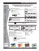
www.mqpower.com PARTS ORDERING PROCEDURES Ordering parts has never been easier! Choose from three easy options: Effective: January 1st, 2006 Order via Internet (Dealers Only): Best Deal! If you have an MQ Account, to obtain a Username and Password, E-mail us at: parts@multiquip.com. Order parts on-line using Multiquip’s SmartEquip website! ■ View Parts Diagrams ■ Order Parts ■ Print Specification Information To obtain an MQ Account, contact your District Sales Manager for more information.
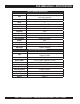
DCA-220SSJ/SSJU — SPECIFICATIONS Table 1. Generator Specifications Model DCA-220SSJ/SSJU Revolving field, self ventilated, open protected type Type synchronous generator Armature Connection Star with Neutral Phase 3 Standby Output 193 KVA (154 KW) Prime Output 176 KVA (140 KW) Voltage 200, OR 400V Frequency 50 Hz Speed 1500 rpm Power Factor 0.8 AUX. AC Power Single Phase, 50 Hz Voltage 100V Output 4.8 KW (2.4 KW X 2) Dry Weight 6,895 lbs. (3,130 kg.) Wet Weight 7,753 lbs. (3,520 kg.) Table 2.
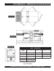
DCA-220SSJ/SSJU — DIMENSIONS (TOP, SIDE AND FRONT) TABLE 3. DIMENSIONS Reference Letter Dimension ft. (mm.) Reference Letter Dimension ft. (mm.) A 37.00 in. (940 mm.) F 137.80 in. (3,500 mm.) B 37.00 in. (940 mm.) G 66.92 in. (1,700 mm.) C 41.33 in. (1,050 mm.) H 48.81 in. (1,240 mm.) D 41.33 in. (1,050 mm.) E 41.33 in. (1,050 mm.) Figure 1. Dimensions 1 DCA-220SSJ/SSJU— OPERATION AND PARTS MANUAL — REV.
DCA-220SSJ/SSJU — SAFETY MESSAGE ALERT SYMBOLS FOR YOUR SAFETY AND THE SAFETY OF OTHERS! Safety precautions should be followed at all times when operating this equipment. Failure to read and understand the Safety Messages and Operating Instructions could result in injury to yourself and others. NOTE This Owner's Manual has been developed to provide complete instructions for the safe and efficient operation of the MQ Power Model DCA-220SSJ/ SSJU Whisperwatt™ Generator.
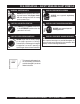
DCA-220SSJ/SSJU — SAFETY MESSAGE ALERT SYMBOLS WARNING - ROTATING PARTS NEVER operate equipment with covers, or guards removed. Keep fingers, hands, hair and clothing away from all moving parts to prevent injury. CAUTION - ACCIDENTAL STARTING ALWAYS place the MPEC control switch in the OFF/RESET position when the generator is not in use. CAUTION - OVER-SPEED CONDITIONS NEVER tamper with the factory settings of the engine governor or settings.
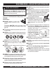
DCA-220SSJ/SSJU — RULES FOR SAFE OPERATION DANGER - READ THIS MANUAL! Failure to follow instructions in this manual may lead to serious injury or even DEATH! This equipment is to be operated by trained and qualified personnel only! This equipment is for industrial use only. ■ ALWAYS check the machine for loosened threads or bolts before starting. ■ NEVER operate the generator in an explosive atmosphere or near combustible materials.
DCA-220SSJ/SSJU — RULES FOR SAFE OPERATION Generator Grounding To guard against electrical shock and possible damage to the equipment, it is important to provide a good EARTH ground. Article 250 (Grounding) of the National Electrical Code (NEC) provides guide lines for proper grounding and specifies that the cable ground shall be connected to the grounding system of the building as close to the point of cable entry as practical.
DCA-220SSJ/SSJU — RULES FOR SAFE OPERATION Maintenance Safety Battery Safety ■ The electrical voltage required to operate the generator can cause severe injury or even death through physical contact with live circuits. Turn all circuit breakers OFF before performing maintenance on the generator. Use the following guidelines when handling the battery: ■ NEVER lubricate components or attempt service on a running machine.
DCA-220SSJ/SSJU — RULES FOR SAFE OPERATION ■ The maximum speed for highway towing is 55 MPH unless posted otherwise. Recommended off-road towing To reduce the possibility of an accident while transporting is not to exceed 15 MPH or less depending on type of the generator on public roads, always make sure the trailer terrain.
DCA-220SSJ/SSJU — GENERATOR DECALS The DCA-220SSJ/SSJU generator is equipped with a number of safety decals (Figures 2 & 3). These decals are provided for operator safety and maintenance information. The illustration below and on the preceding page show the decals as they appear on the machine. Should any of these decals become unreadable, replacements can be obtained from your dealer. Figure 2. Generator Decals PAGE 14 — DCA-220SSJ/SSJU— OPERATION AND PARTS MANUAL — REV.
DCA-220SSJ/SSJU — GENERATOR DECALS Figure 3. Generator Decals (Cont inued) 1 DCA-220SSJ/SSJU— OPERATION AND PARTS MANUAL — REV.
DCA-220SSJ/SSJU — INSTALLATION Figure 4. Typical Generator Grounding Application PAGE 16 — DCA-220SSJ/SSJU— OPERATION AND PARTS MANUAL — REV.
DCA-220SSJ/SSJU — INSTALLATION Outdoor Installation Generator Grounding Install the generator in a area that is free of debris, bystanders, and overhead obstructions. Make sure the generator is on secure level ground so that it cannot slide or shift around. Also install the generator in a manner so that the exhaust will not be discharged in the direction of nearby homes. To guard against electrical shock and possible damage to the equipment, it is important to provide a good EARTH ground.
DCA-220SSJ/SSJU — GENERAL INFORMATION DCA-220SSJ/SSJU Whisperwatt™ Series Familiarization Generator The MQ Power Model DCA-220SSJ/SSJU is a 140 kW generator (Figure 5) that is designed as a high quality portable (requires a trailer for transport) power source for telecom sites, lighting facilities, power tools, submersible pumps and other industrial and construction machinery.
DCA-220SSJ/SSJU — MAJOR COMPONENTS 3 1 4 220 5 6 7 2 8 Figure 5. Major Components Table 4. Generator Major Components AUTO MANUAL OFF/RESET LOW OIL PRESSURE HIGH COOLANT TEMPERATURE OVERCRANK OVERSPEED ENGINE RUNNING 9 ITEM NO.
DCA-220SSJ/SSJU — DIAGNOSTIC DISPLAY 3. 4. 5. 6. Figure 6. Diagnostic Display Panel 7. Right Arrow Button – Press this button to scroll through the screen either moving the parameter selection toward the right or downward. Enter Key Button – Press this button to select the parameter that is highlighted on the screen. Emergency Stop LED – When lit (RED) indicates a major fault has occured. This condition will shudown the generator.
DCA-220SSJ/SSJU — DIAGNOSTIC DISPLAY First Time Start Up 1. 2. When power is first applied to the diagnostic display, the “Logo” is displayed. The first seven items of the “Main Menu” will be displayed. Touching the “Arrow Buttons” will scroll through the menu selection. GO TO 1-UP DISPLAY LANGUAGES STORED CODES ENGINE CONFG SETUP 1-UP DISPLAY SETUP-4-UP DISPLAY SELECT UNITS 2. The “Wait to Start” message will be displayed for 3. engines with a pre-startup sequence.
DCA-220SSJ/SSJU — DIAGNOSTIC DISPLAY 2. The language choices will be displayed. Use the “Arrow” buttons to scroll through the selections and touch “Enter” to make a selection. 4. If the word “MORE” appears above the “Arrow Buttons” there are more stored fault codes that may be viewed. Use the “Arrow Buttons” to scroll to the next Stored Diagnostic Code. ENGLISH ESPANOL FRANCAIS DEUTSCH 1 of x SPN110 FMI10 HIGH COOLANT TEMP MORE 3. Now that you have selected the language, touch the 5.
DCA-220SSJ/SSJU — DIAGNOSTIC DISPLAY 2. The main menu will pop up on the display. Use the “Arrow FAULTS AND WARNINGS Buttons” to scroll through the menu until the “Engine Configuration” menu item has been highlighted. Auxiliary Gage Fault 1. GO TO 1-UP DISPLAY STORED CODES ENGINE CONFG SETUP 1-UP DISPLAY SETUP-4-UP DISPLAY SELECT UNITS ADJUST BACKLIGHT During normal operation the single or four parameter screen will be displayed. 0 1500 3000 98% 1000 RPM LOAD RPM ENG RPM 14.
DCA-220SSJ/SSJU — DIAGNOSTIC DISPLAY ! 4. Indicates Auxiliary Gage Fault ! Indicates Fault Warning ! Indicates Derate or Shutdown Condition Fault 5. Touching the “Enter Button” will redisplay the hidden fault. Touching the “Enter Button” once again will hide the fault and return the screen to the single or four parameter display. NOTE: The fault can only be cleared by correcting the cause of the fault condition. 1 of x SPN110 FMI10 HIGH COOLANT TEMP MORE 5.
DCA-220SSJ/SSJU — DIAGNOSTIC DISPLAY 5. Shut Down Codes 1. During normal operation the single or four parameter screen will be displayed. Touching the “Enter Button” once again will hide the fault and return the screen to the single or four parameter display. 1 of x 0 3000 1500 98% 1000 RPM LOAD RPM ENG RPM 14.2 57 PSI SPN110 FMI10 HIGH COOLANT TEMP 1800 RPM MORE BATT VOLT ENG RPM COOL TEMP 2. 6.
DCA-220SSJ/SSJU — DIAGNOSTIC DISPLAY 3. Once the “Adjust Backlight” menu item has been Contrast Adjustment highlighted touch the “Enter Button” to activate the 1. Starting at the single or four engine parameter display, “Adjust Backlight” function. touch the “Menu Button”. GO TO 1-UP DISPLAY STORED CODES ENGINE CONFG SETUP 1-UP DISPLAY SETUP-4-UP DISPLAY SELECT UNITS ADJUST BACKLIGHT 4. 0 1500 3000 98% 1000 RPM LOAD RPM ENG RPM 14.
DCA-220SSJ/SSJU — DIAGNOSTIC DISPLAY Select Units 1. 5. Touch the “Enter Button” to select the highlighted units. Starting at the single or four engine parameter display touch the “Menu Button”. 0 1500 3000 98% 1000 RPM LOAD RPM ENG RPM 14.2 57 PSI ENGLISH METRIC KPA METRIC BAR 1800 RPM ENG RPM COOL TEMP BATT VOLT OIL PRES 6. 2. The main menu will pop up on the display. Use the arrow buttons to scroll through the menu until the “Select Units” is highlighted.
DCA-220SSJ/SSJU — DIAGNOSTIC DISPLAY 3. Once the “Setup 1-up Display” menu icon has been 7. highlighted touch the “Enter Button” to access the “Setup 1-up display” function. GO TO 1-UP DISPLAY STORED CODES ENGINE CONFG SETUP 1-UP DISPLAY SETUP-4-UP DISPLAY SELECT UNITS ADJUST BACKLIGHT 4. A message indicating the “Single Engine” parameter display parameters are reset to the factory defaults will be displayed, then the display will return to the “Custom Setup” menu.
DCA-220SSJ/SSJU — DIAGNOSTIC DISPLAY 11. Touch the “Enter Button” to deselect the selected parameter removing it from the list of parameters being displayed on the 1-up display. 16. Touching the “Enter Button” toggles the “Automatic Scan” function on. USE DEFAULTS CUSTOM SETUP AUTOMATIC SCAN ON 1 ENGINE SPEED PERCENT LOAD AT CURRENT RPM 3 2 ENGINE OIL PRESSURE ENGINE COOLANT TEMPERATURE 12. Use the “Arrow Button” to scroll and highlight the desired parameter that has not been selected for display. 17.
DCA-220SSJ/SSJU — DIAGNOSTIC DISPLAY Setup 4-Up Display 1. 5. The “Use Defaults” screen will be displayed during the resetting period then will automatically return to the From the single or four engine parameter display touch “Setup 4- Up Display” menu. the “Menu Button”. 0 1500 3000 98% 1000 RPM LOAD RPM ENG RPM 14.2 57 PSI 1800 RPM ENG RPM COOL TEMP 2. BATT VOLT RESTORED TO DEFAULTS OIL PRES The main menu will pop up on the display.
DCA-220SSJ/SSJU — DIAGNOSTIC DISPLAY 9. The parameter that is highlighted is the selected parameter for the screen. Use the “Arrow Buttons” to highlight the new parameter to be placed in the quadrant selected in the previous screen. 14. Touch the “Menu Button” to return to the main menu.
DCA-220SSJ/SSJU — DIAGNOSTIC DISPLAY 4. Touch “Select” to enter the “Gage Data” display. When 8. “Gage Data” is selected the PowerView will communicate with the analog gages at a fixed rate of 38.4k Band, 8 data bits, no parity check, 1 stop bits, half duplex. SOFTWARE VERSION MURPHY: X.XX GAGE DATA REMOVE ALL GAGES SOFTWARE VERSION MODBUS SETUP FAULT CONVERSION ADJUST BACKLIGHT DEMO MODE ON 9. 5. Use the “Arrow Buttons” to scroll through the items or touch “Menu” to return to the “Utilities” menu.
DCA-220SSJ/SSJU — DIAGNOSTIC DISPLAY 11. Touch the “Menu” button to return to “Utilities” menu. 4. Touch the “Menu button again to return to the “Main” menu. STORED CODES ENGINE CONFG SETUP 1-UP DISPLAY SETUP-4-UP DISPLAY SELECT UNITS ADJUST BACKLIGHT UTILITIES Use the “Arrows” to scroll down to and highlight either the “Slave Active or Master Active” modes. Touch the “Enter” button to toggle between master and slave.
DCA-220SSJ/SSJU — DIAGNOSTIC DISPLAY GLOSSARY (Troubleshooting information) CANBUS FAILURE Diagnostic Display has not received any CAN messages for at least 30 seconds. NO DATA Diagnostic Display has not received the particular message being displayed for at least 5 seconds. NOT SUPPORTED Diagnostic Display has received a message from the ECU stating the displayed message is not supported DATA ERROR Diagnostic Display has received an error message from the ECU for the displayed message.
DCA-220SSJ/SSJU — GENERATOR CONTROL PANEL Figure 7. Generator Control Panel The definitions below describe the controls and functions of Located behind the generator control panel is the Generator the DCA-220SSJ/SSJU Generator Control Panel (Figure 7). Control Box. This box contains some of the necessary 1. Frequency Meter – Indicates the output frequency in electronic components required to make the generator function. hertz (Hz). Normally 50 Hz. 2. 3. 4. 5. 6. 7.
DCA-220SSJ/SSJU — ENGINE OPERATING PANEL The definitions below describe the controls and functions of the DCA-220SSJ/SSJU Engine Operating Panel (Figure 8). Figure 8. Engine Operating Panel 1. 2. 3. Panel Light – Normally used in dark areas or at night time. When activated, panel lights will illuminate. When the generator is not in use be sure to turn the panel light switch to the OFF position. Panel Light Switch – When activated will turn on control panel light.
DCA-220SSJ/SSJU — ENGINE OPERATING PANEL 8. 9. 10. 11. 12. 13. Engine Speed Switch – This switch controls the speed of the engine (low/high). Pre-Heat Lamp – When lit, indicates engine is in the pre-heating mode (for starting during cold weather operating conditiions). When lamp goes off engine is ready for starting. Warning Lamp – This lamp will illuminate when a critical engine fault has occured.
DCA-220SSJ/SSJU — OUTPUT TERMINAL PANEL FAMILIARIZATION Output Terminal Panel Output Terminal Familiarization The Output Terminal Panel (Figure 9) shown below is located The “Output Terminal Panel ” (Figure 8) is provided with the on the right-hand side (left from control panel) of the generator. following: Lift up on the cover to gain access to receptacles and terminal ■ Three (3) 100/200V output receptacles @ 50 amp lugs.
DCA-220SSJ/SSJU — OUTPUT TERMINAL PANEL FAMILIARIZATION 100 VAC GFCI Receptacles There are two 100 VAC, 20 amp GFCI (Duplex Nema 5-20R) recepacles provided on the output terminal panel. These receptacles can be accessed in any voltage selector switch position. Each receptacle is protected by a 20 amp circuit breaker. These breakers are located directly above the GFCI receptacles.
DCA-220SSJ/SSJU — OUTPUT TERMINAL PANEL FAMILIARIZATION Over Current Relay Loads can be connected to the generator by the Ouput An over current relay (Figure 15) is connected to the main Terminal Lugs or the convienience receptacles (Figure 14). circuit breaker. In the event of an overload, both the circuit Make sure to read the operation manual before attempting breaker and the over current relay may trip.
DCA-220SSJ/SSJU — LOAD APPLICATION Single Phase Load Three Phase Load Always be sure to check the nameplate on the generator and equipment to insure the wattage, amperage, frequency, and voltage requirements are satisfactorily supplied by the generator for operating the equipment. When calculating the power requirements for 3-phase power use the following equation: Generally, the wattage listed on the nameplate of the equipment is its rated output.
DCA-220SSJ/SSJU — GENERATOR OUTPUTS Generator Amperage Generator Output Voltages A wide range of voltages are available to supply voltage for Tables 8 and 9 describe the generator’s current output capamany different applications. Voltages are selected by apply- bility for both 1Ø-phase and 3Ø phase applications. ing jumpers (6) to the voltage change-over board (Figure 15). To obtain some of the voltages as listed in Table 6 (see Table 8.
DCA-220SSJ/SSJU — GENERATOR OUTPUTS/ GAUGE READING Maximum Amps Table 10 shows the maximum amps the generator can provide. DO NOT exceed the maximum amps as listed. Table 10. Generator Maximum Amps Model DCA-220SSJ/SSJU Rated Voltage Maximum Amps Single Phase 100 Volt Single Phase 200 Volt Three Phase 200 Volt Three Phase 400 Volt 466 amps (4 wire) 233 amps (4 wire) 508 amps Figure 17. AC Voltmeter Figure 18.
DCA-220SSJ/SSJU — OUTPUT TERMINAL PANEL CONNECTIONS UVWO Terminal Output Voltages Various output voltages can be obtained using the UVWO output terminal lugs. The voltages at the terminals are dependent on the placement of the jumpers plates (6) on the Voltage Change-Over Board and the adjustment of the Figure 23. Voltage Regulator Knob Voltage Regulator Control Knob.
DCA-220SSJ/SSJU — OUTPUT TERMINAL PANEL CONNECTIONS 3Ø-400V UVWO Terminal Output Voltages 1. Jumper the voltage change-over board for 480V operation as shown in Figure 26. This configuration uses 6 jumper plates in 3 different positions. Remember there are 2 jumper plates at every position. Every jumper plate must be used. 1Ø-400V UVWO Terminal Output Voltages 1. Make sure the voltage change-over board is jumpered for 480V operation as shown in Figure 26. 2.
DCA-220SSJ/SSJU — PRE-SETUP Fuel Check Circuit Breakers To protect the generator from an overload, a 3-pole, 600 amp, main circuit breaker is provided to protect the U,V, and W Output Terminals from overload. In addition two single-pole, 20 amp GFCI circuit breakers are provided to protect the GFCI receptacles from overload. Three 50 amp load circuit breakers have also been provided to protect the auxiliary receptacles from overload.
DCA-220SSJ/SSJU — PRE-SETUP Refueling Procedure: 3. WARNING - RESPIRATORY HAZARDS Open cabinet doors on the “right side” of the generator (from generator control panel position). Remove fuel cap and fill tank (Figure 33). Diesel fuel and its vapors are dangerous to your health and the surrounding environment. Avoid skin contact and/or inhaling fumes. 1. Level Tanks – Make sure fuel cells are level with the ground.
DCA-220SSJ/SSJU — PRE-SETUP Coolant (Antifreeze) John Deere recommends Antifreeze/Summer Coolant for use in thier engines, which can be purchased in concentrate (and mixed with 50% demineralized water) or pre-diluted. See the John Deere Engine Owner's Manual for further details WARNING - BURN HAZARDS Cleaning the Radiator The engine may overheat if the radiator fins become overloaded with dust or debris. Periodically clean the radiator fins with compressed air.
DCA-220SSJ/SSJU — PRE-SETUP When connecting battery do the following: Battery This unit is of negative ground DO NOT connect in reverse. 1. NEVER connect the battery cables to the battery terminals when the MPEC Control Switch is in either Always maintain battery fluid level between the specified the MANUAL or AUTO position. ALWAYS make sure that marks. Battery life will be shortened, if the fluid level are not properly maintained.
DCA-220SSJ/SSJU — GENERATOR START-UP PROCEDURE (MANUAL) Before Starting CAUTION - LETHAL EXHAUST HAZARD The engine's exhaust contains harmful emissions. ALWAYS have adequate ventilation when operating. Direct exhaust away from nearby personnel. WARNING - STARTING THE GENERATOR NEVER! manually start the engine with the main, GFCI or auxiliary circuit breakers in the ON (closed) position. 3. Make sure the the voltage change-over board has been configured for the desired output voltage. 4.
DCA-220SSJ/SSJU — GENERATOR START-UP PROCEDURE (MANUAL) When the MPEC Control switch is 8. To restart the engine due to error codes, place the MPEC Control Switch in the MANUAL position (Figure 42) placed in the manual position, NOTE preheating of the glow plugs will begin 9. If the engine is running smoothly, place the engine automatically and the preheat lamp speed switch (Figure 44) in the “HIGH” (up) position. will stay lit until the glow plugs are warmed.
DCA-220SSJ/SSJU — GENERATOR START-UP PROCEDURE (MANUAL) 18. Place the main, GFCI, and aux. circuit breakers in the ON position (Figure 53). Figure 48. Voltage Adjust Control Knob 14. The ammeter (Figure 49) will indicate zero amps with no load applied. When a load is applied, the ammeter will indicate the amount of current that the load is drawing from the generator. Figure 49. Ammeter (No Load) 15. The engine oil pressure gauge (Figure 50) will indicate the oil pressure of the engine.
DCA-220SSJ/SSJU — GENERATOR START-UP PROCEDURE (AUTO MODE) WARNING - AUTO MODE MAINTENANCE When running the generator in the AUTO mode, remember the generator can start up at any time without warning. NEVER attempt to perform any maintenance when the generator is in the auto mode. When starting generator in AUTO mode use the "Manual Start-up" procedure except where noted (see below). 1. Perform steps 1 through 6 in the Before Starting section as outlined in the Manual Starting Procedure. 2.
DCA-220SSJ/SSJU — GENERATOR SHUT-DOWN PROCEDURES WARNING - SHUTTING DOWN THE GENERATOR NEVER stop the engine suddenly except in an emergency. CAUTION - DIAGNOSTIC SWITCH Emergency Shutdown Procedure 1. To shut-down the engine in the event of an emergency, push the Emergency Stop Button (Figure 58). 2. Switch the MAIN, GFCI and LOAD (Figure 38) circuit breakers to OFF position. ALWAYS make sure the diagnostic switch is placed in the OFF position before attempting to shut down the generator.
DCA-220SSJ/SSJU — MAINTENANCE (ENGINE) 10 Hrs DAILY TABLE 14.
DCA-220SSJ/SSJU — MAINTENANCE (ENGINE) Flushing Out Radiator and Replacing Coolant Air Removal If air enters the fuel injection system of a diesel engine, Open both cocks located at the crankcase side and at the lower part of the radiator and drain coolant. Open the starting becomes impossible. After running out of fuel, or radiator cap while draining. Remove the overflow tank after disassembling the fuel system, bleed the system and drain. according to the following procedure.
DCA-220SSJ/SSJU — MAINTENANCE (HEATER/CHARGER) If the generator will be used daily, the battery should normally not require charging. If the generator will be idle (not used) for long periods of time, apply power to the battery charger receptacle via commercial power using an power cord of adequate size. NOTE To ensure adequate starting capability, always have power applied to the generator's internal battery charger. 1 DCA-220SSJ/SSJU— OPERATION AND PARTS MANUAL — REV.
DCA-220SSJ/SSJU — MAINTENANCE (TRAILER ) 8. Tire Size - Indicates the diameter of the tire in inches (10,12,14, etc.), and the width in millimeters This section is intended to provide the user with generic (175,185,205, etc.). The tire diameter must match the trailer service and maintenance information. The service and diameter of the tire rim. maintenance guidelines referenced in this section refer to a wide range of trailers. 9.
DCA-220SSJ/SSJU — MAINTENANCE (TRAILER ) Brakes Trailer brakes should be inspected the first 200 miles of operation. This will allow the brake shoes and drums to seat properly. After the first 200 mile interval, inspect the brakes every 3,000 miles. If driving over rough terrain, inspect the brakes more frequently. Figure 59 displays the major hydraulic surge brake components that will require inspection and maintenance.
DCA-220SSJ/SSJU — MAINTENANCE (TRAILER) Tires/Wheels/Lug Nuts Tires and wheels are a very important and critical components of the trailer. When specifying or replacing the trailer wheels it is important the wheels, tires, and axle are properly matched. CAUTION - EYESIGHT HAZARD Suspension The leaf suspension springs and associated components (Figure 61) should be visually inspected every 6,000 miles for signs of excessive wear, elongation of bolt holes, and loosening of fasteners.
DCA-220SSJ/SSJU — MAINTENANCE (TRAILER) Lug Nut Torque Requirements It is extremely important to apply and maintain proper wheel mounting torque on the trailer. Be sure to use only the fasteners matched to the cone angle of the wheel. Proper procedure for attachment of the wheels is as follows: 1. Start all wheel lug nuts by hand. 2. Torque all lug nuts in sequence (see Figure 62). DO NOT torque the wheel lug nuts all the way down. Tighten each lug nut in 3 separate passes as defined by Table 18. 3.
DCA-220SSJ/SSJU — TRAILER WIRING DIAGRAM Figure 63. Trailer/Towing Vehicle Wiring Diagram PAGE 64 — DCA-220SSJ/SSJU— OPERATION AND PARTS MANUAL — REV.
DCA-220SSJ/SSJU — GENERATOR WIRING DIAGRAM Figure 64. Generator Wiring Diagram 1 DCA-220SSJ/SSJU— OPERATION AND PARTS MANUAL — REV.
DCA-220SSJ/SSJU — ENGINE WIRING DIAGRAM Figure 65. Engine Wiring Diagram PAGE 66 — DCA-220SSJ/SSJU— OPERATION AND PARTS MANUAL — REV.
DCA-220SSJ/SSJU — TROUBLESHOOTING (GENERATOR) Practically all breakdowns can be prevented by proper handling and maintenance inspections, but in the event of a breakdown, use Table 19 shown below for diagnosis of the Generator. If the problem cannot be remedied, consult our company's business office or service plant. TABLE 19.
DCA-220SSJ/SSJU — TROUBLESHOOTING (ENGINE CONTROLLER) Practically all breakdowns can be prevented by proper handling and maintenance inspections, but in the event of a breakdown, use Table 20 (Engine Controller Troubleshooting) as a basic guideline for troubleshooting the Microprocessor Engine Controller unit (MPEC). If the problem cannot be remedied, consult our company's business office or service plant. TABLE 20. ENGINE CONTROLLER TROUBLESHOOTING (MPEC) SYMPTOM Low oil pressure light is on.
NOTE PAGE 1 DCA-220SSJ/SSJU— OPERATION AND PARTS MANUAL — REV.
DCA-220SSJ/SSJU — EXPLANATION OF CODE IN REMARKS COLUMN The following section explains the different symbols and remarks used in the Parts section of this manual. Use the help numbers found on the back page of the manual if there are any questions. The contents and part numbers listed in the parts section are subject to change without notice. Multiquip does not guarantee the availibility of the parts listed. PART NO. PART NAME QTY. 12345 BOLT ....................... 1 .... WASHER, 1/4 IN. ...........
DCA-220SSJ/SSJU — SUGGESTED SPARE PARTS DCA-220SSJ/SSJU WHISPER WATTGENRATOR W/JOHN DEERE 6068HF485 TURBO DIESEL ENGINE 1 TO 3 UNITS Qty. P/N Description 1 ......... M4310500803 ..... HOSE, RADIATOR UPPER 1 ......... M4310500903 ..... HOSE, RADIATOR LOWER 1 ......... 060202011062 .... RADIATOR CAP 1 ......... 0845500104 ........ FUEL CAP 1 ......... 0602015230 ........ V-BELT SET, FAN 1 ......... 0602122272 ........ UNIT, OIL PRESSURE 1 ......... 0602122281 ........ SWITCH, OIL PRESSURE 1 .........
DCA-220SSJ/SSJU — GENERATOR ASSY. GENERATOR ASSY. PAGE 72 — DCA-220SSJ/SSJU— OPERATION AND PARTS MANUAL — REV.
DCA-220SSJ/SSJU — GENERATOR ASSY. GENERATOR ASSY. NO. 1 1-1 * 1-2 * 1-3 * 1-4 * 1-4A 1-4B 1-5 1-6 1-7 1-8 1-9 1-10 1-11 1-12 1-13 2 3 4 5 6 7 7-1# 7-2# 7-3# 7-4# 7-5# 7-6# 7-7# 7-8# 7-9# 7-10# 7-11# 7-12# 8 9 PART NO.
DCA-220SSJ/SSJU — GENERATOR ASSY. (CONT.) GENERATOR ASSY. PAGE 74 — DCA-220SSJ/SSJU— OPERATION AND PARTS MANUAL — REV.
DCA-220SSJ/SSJU — GENERATOR ASSY. (CONT.) GENERATOR ASSY. (CONT.) NO. 10 10A 10B 11 12 13 14 14A 14B 15 16 17 18 19 20 20A 20B 21 22 22A 23 PART NO. 0012110065 0042610000 0041210000 0017112045 C1154400004 C1154300004 0010106060 0040006000 0041206000 C1154400103 0017106016 0343205150 0043605000 C1132300114 0010106030 0041206000 0600815000 0605000012 0030020000 0040020000 0070506907 PART NAME HEX. HEAD BOLT SPRING WASHER PLAIN WASHER HEX. HEAD BOLT COVER, BEARING GASKET, BEARING HEX.
DCA-220SSJ/SSJU— CONTROL PANEL ASSY. CONTROL PANEL ASSY. PAGE 76 — DCA-220SSJ/SSJU— OPERATION AND PARTS MANUAL — REV.
DCA-220SSJ/SSJU— CONTROL PANEL ASSY. CONTROL PANEL ASSY. NO. 1 2 2-1 2-2 3 4 5 6 7 8 9 10 11 12 13 13A 14 15 16 17 18 19 20 21 22 23 23A 24 24A 25 26 27 28 28A 29 30 PART NO.
DCA-220SSJ/SSJU— CONTROL BOX ASSY. CONTROL BOX ASSY. PAGE 78 — DCA-220SSJ/SSJU— OPERATION AND PARTS MANUAL — REV.
DCA-220SSJ/SSJU— CONTROL BOX ASSY. CONTROL BOX ASSY. NO. 1 2 3 4 5 6 7 8 9 10 11 12 13 14 15 16 17 18 19 20 20A 21 22 23 24 25 25A 25B 26 27 28 29 30 30A 30B 31 32 33 34 35 36 37 PART NO.
DCA-220SSJ/SSJU— CONTROL BOX ASSY. (CONT) CONTROL BOX ASSY. (CONT.) PAGE 80 — DCA-220SSJ/SSJU— OPERATION AND PARTS MANUAL — REV.
DCA-220SSJ/SSJU— CONTROL BOX ASSY. (CONT) CONTROL BOX ASSY. NO. 38 39 39A 39B 40 41 42 43 44 45 46 47 48 49 50 51 52 52A 53 54 PART NO.
DCA-220SSJ/SSJU— ENGINE AND RADIATOR ASSY. ENGINE AND RADIATOR ASSY. PAGE 82 — DCA-220SSJ/SSJU— OPERATION AND PARTS MANUAL — REV.
DCA-220SSJ/SSJU— ENGINE AND RADIATOR ASSY. ENGINE AND RADIATOR ASSY. NO. 1 1-1 1-2 1-3 2 3 4 5 6 7 8 9 10 11 12 12A 13 14 15 16 17 17A 18 19 20 21 22 23 24 25 26 27 27A 28 28A 29 29A 29B 29C 30 31 PART NO.
DCA-220SSJ/SSJU— ENGINE AND RADIATOR ASSY. ENGINE AND RADIATOR ASSY. PAGE 84 — DCA-220SSJ/SSJU— OPERATION AND PARTS MANUAL — REV.
DCA-220SSJ/SSJU— ENGINE AND RADIATOR ASSY. ENGINE AND RADIATOR ASSY. NO. 32 33 34 35 36 37 38 39 40 41 42 43 44 45 46 47 48 49 50 51 52 53 54 54A 54B 55 56 57 58 59 60 61 62 63 64 65 66 67 68 69 PART NO.
DCA-220SSJ/SSJU— ENGINE AND RADIATOR ASSY. ENGINE AND RADIATOR ASSY. PAGE 86 — DCA-220SSJ/SSJU— OPERATION AND PARTS MANUAL — REV.
DCA-220SSJ/SSJU— ENGINE AND RADIATOR ASSY. ENGINE AND RADIATOR ASSY. NO. 70 71 72 73 74 75 76 77 78 79 80 82 83 84 85 86 86A 87 88 89 90 91 PART NO. 0602021070 0269200660 0802081003 0602010900 M4316100103 0016910025 0199901500 0193601600 0193600700 0605515106 0191601700 M4483600003 0016908020 0602017090 0602042601 0017110020 0040510000 0602220911 0602220910 0602202452 0602015230 813NLU0000T PART NAME QTY.
DCA-220SSJ/SSJU— OUTPUT TERMINAL ASSY. OUTPUT TERMINAL ASSY. PAGE 88 — DCA-220SSJ/SSJU— OPERATION AND PARTS MANUAL — REV.
DCA-220SSJ/SSJU— OUTPUT TERMINAL ASSY. OUTPUT TERMINAL ASSY. NO. 1 2 3 4 5 6 7 8 9 10 11 12 12A 12B 13 13A 14 14A 14B 14C 15 16 17 18 19 20 21 22 23 24 25 25-1 26 27 28 29 29A 30 31 32 33 34 35 36 37 38 39 40 41 PART NO.
DCA-220SSJ/SSJU— BATTERY ASSY. BATTERY ASSY. PAGE 90 — DCA-220SSJ/SSJU— OPERATION AND PARTS MANUAL — REV.
DCA-220SSJ/SSJU— BATTERY ASSY. BATTERY ASSY. NO. 1 2 3 4 5 6 7 8 9 10 11 12 13 14 15 16 17 PART NO. 0168614551 C9109100604 0805000904 0805002904 0037808000 0040008000 0041608000 C1346600004 C1346600104 0347010003 0208110000 0845040414 0845041304 0017116030 0040516000 0040520000 PART NAME QTY. REMARKS BATTERY, 145G51 1 BATTERY SHEET 1 BATTERY BAND 1 BATTERY BOLT 2 WING NUT 2 SPRING WASHER 2 PLAIN WASHER 2 BATTERY CABLE 1 BATTERY CABLE 1 EARTH CABLE .........................................................
DCA-220SSJ/SSJU— MUFFLER ASSY. MUFFLER ASSY. PAGE 92 — DCA-220SSJ/SSJU— OPERATION AND PARTS MANUAL — REV.
DCA-220SSJ/SSJU— MUFFLER ASSY. MUFFLER ASSY. NO. 1 2 3 4 5 6 6A 6B 7 8 9 10 11 PART NO. M4330100602 0016910025 M4333000303 0602325066 M4333200004 0010112055 0040012000 0041212000 M4330300004 0016908020 M4333300304 0016908020 0602326062 PART NAME MUFFLER HEX. HEAD BOLT EXHAUST PIPE CLAMP GASKET HEX. HEAD BOLT SPRING WASHER PLAIN WASHER COVER HEX. HEAD BOLT BRACKET HEX. HEAD BOLT U-BOLT SET QTY. 1 4 1 1 1 4 4 4 2 4 1 4 1 REMARKS 1 DCA-220SSJ/SSJU— OPERATION AND PARTS MANUAL — REV.
DCA-220SSJ/SSJU— FUEL TANK ASSY. FUEL TANK ASSY. PAGE 94 — DCA-220SSJ/SSJU— OPERATION AND PARTS MANUAL — REV.
DCA-220SSJ/SSJU— FUEL TANK ASSY. FUEL TANK ASSY. NO. 1 1-1 1-2 2 2A 3 4 5 6 7 8 9 10 11 12 13 14 15 16 PART NO.
DCA-220SSJ/SSJU— ENCLOSURE ASSY. ENCLOSURE ASSY. ADD THE FOLLOWING DIGITS AFTER THE PART NUMBER WHEN ORDERING ANY PAINTED PANEL TO INDICATE COLOR OF UNIT: 1-ORANGE 2-WHITE 3-SPECTRUM GREY 4-SUNBELT GREEN 5-BLACK 6-CATERPILLAR YELLOW 7-CATO GOLD 8-RED THE SERIAL NUMBER MAY BE REQUIRED. PAGE 96 — DCA-220SSJ/SSJU— OPERATION AND PARTS MANUAL — REV.
DCA-220SSJ/SSJU— ENCLOSURE ASSY. ENCLOSURE ASSY. NO. 1 2 3 4 4A 5 5A 6 7 8 8A 9 10 11 12 12A 13 13A 14 15 15A 16 17 17A 18 18A 18B 18C 19 19A 19B 19C 20 20A 21 22 22A PART NO.
DCA-220SSJ/SSJU— ENCLOSURE ASSY. (CONT.) ENCLOSURE ASSY. (CONT.) ADD THE FOLLOWING DIGITS AFTER THE PART NUMBER WHEN ORDERING ANY PAINTED PANEL TO INDICATE COLOR OF UNIT: 1-ORANGE 2-WHITE 3-SPECTRUM GREY 4-SUNBELT GREEN 5-BLACK 6-CATERPILLAR YELLOW 7-CATO GOLD 8-RED THE SERIAL NUMBER MAY BE REQUIRED. PAGE 98 — DCA-220SSJ/SSJU— OPERATION AND PARTS MANUAL — REV.
DCA-220SSJ/SSJU— ENCLOSURE ASSY. (CONT.) ENCLOSURE ASSY. (CONT.) NO. 24 25 26 27 28 28A 29 30 30A 31 31A 32 33 34 35 36 36A 37 38 39 39A 40 40A 41 42 43 44 45 46 47 48 49 49A 50 50A 50B PART NO.
DCA-220SSJ/SSJU— ENCLOSURE ASSY. (CONT.) ENCLOSURE ASSY. (CONT.) ADD THE FOLLOWING DIGITS AFTER THE PART NUMBER WHEN ORDERING ANY PAINTED PANEL TO INDICATE COLOR OF UNIT: 1-ORANGE 2-WHITE 3-SPECTRUM GREY 4-SUNBELT GREEN 5-BLACK 6-CATERPILLAR YELLOW 7-CATO GOLD 8-RED THE SERIAL NUMBER MAY BE REQUIRED. PAGE 100 — DCA-220SSJ/SSJU— OPERATION AND PARTS MANUAL — REV.
DCA-220SSJ/SSJU— ENCLOSURE ASSY. (CONT.) ENCLOSURE ASSY. (CONT.) NO. 51 51A 52 52A 53 53A 54 54A 55 55A 56 56A 57 57A 58 58A 59 60 61 62 62A 63 64 65 66 66A 67 67A 68 69 70 71 PART NO.
DCA-220SSJ/SSJU— RUBBER SEALS ASSY. RUBBER SEALS ASSY. PAGE 102 — DCA-220SSJ/SSJU— OPERATION AND PARTS MANUAL — REV.
DCA-220SSJ/SSJU— RUBBER SEALS ASSY. RUBBER SEALS ASSY. NO. PART NO. 1 0229201240 2 0228900945 3 0228901200 4 0228901260 5 0228901055 6 0228900600 7 0228900660 8 0229201060 9 0229200660 10 0228801050 11 0228800595 12 0228800635 13 0228100560 14 0228100370 15 0229201020 16 0228301200 PART NAME SEAL RUBBER SEAL RUBBER SEAL RUBBER SEAL RUBBER SEAL RUBBER SEAL RUBBER SEAL RUBBER SEAL RUBBER SEAL RUBBER SEAL RUBBER SEAL RUBBER SEAL RUBBER SEAL RUBBER SEAL RUBBER SEAL RUBBER SEAL RUBBER QTY.
DCA-220SSJ/SSJU— NAMEPLATE AND DECALS ASSY. NAMEPLATE AND DECALS ASSY. PAGE 104 — DCA-220SSJ/SSJU— OPERATION AND PARTS MANUAL — REV.
DCA-220SSJ/SSJU— NAMEPLATE AND DECALS ASSY. NAMEPLATE AND DECALS ASSY. NO. PART NO. PART NAME QTY. REMARKS 1-1 M4550000303 DECAL; OPERATING PROCEDURES ........................ 1 ........... M45000030 1-2 B9521100404 DECAL; SAFETY INSTRUCTIONS ............................. 1 ........... B92110040 1-3 C9521100003 DECAL; CAUTION ....................................................... 2 ........... C92110000 CONTROL PANEL & BOX GROUP 2-1 C1550000102 DECAL; CONTROL PANEL .........................................
TERMS AND CONDITIONS OF SALE — PARTS Effective: February 22, 2006 PAYMENT TERMS 5. Parts must be in new and resalable condition, in the original Multiquip package (if any), and with Multiquip part numbers clearly marked. 6. The following items are not returnable: Terms of payment for parts are net 30 days. FREIGHT POLICY All parts orders will be shipped collect or prepaid with the charges added to the invoice. All shipments are F.O.B. point of origin.
NOTE PAGE 1 DCA-220SSJ/SSJU— OPERATION AND PARTS MANUAL — REV.
PARTS AND OPERATION MANUAL OPERATION AND PARTS MANUAL HERE’S HOW TO GET HELP PLEASE HAVE THE MODEL AND SERIAL NUMBER ON-HAND WHEN CALLING MQ Power 1800 Water Ridge Rd. Tel. (800) 883-2551 Suite 500/600 Fax (972) 315-1847 Lewisville, TX 75057 Contact: mqpower@multiquip.com Web: www.mqpower.com MQ Parts Department 800-427-1244 Fax: 800-672-7877 310-537-3700 Fax: 310-637-3284 Service/Tech Support/Warranty 800-835-2551 Fax: 310-638-8046 © COPYRIGHT 2009, MULTIQUIP INC.