OPERATION AND PARTS MANUAL © COPYRIGHT 2003, MULTIQUIP INC. MQ POWER DCA-125SSJU DCA-125SSJU2 PORTABLE GENERATOR (STANDARD) PARTS LIST NO. 3870300064A S/N7500469 UP TO 7500507-125SSJU S/N FROM 7500508-125SSJU2 Revision #4 (06/03/03) MULTIQUIP INC.. PARTS DEPARTMENT: 18910 WILMINGTON AVE. 800-427-1244 CARSON, CALIFORNIA 90746 FAX: 800-672-7877 310-537-3700 SERVICE DEPARTMENT: 800-421-1244 800-835-2551 FAX:310-537-3927 FAX:310-638-8046 E-mail:mq@multiquip.com z www:multiquip.
PAGE 2 — DCA-125SSJU SERIES (STANDARD) — PARTS AND OPERATION MANUAL — REV.
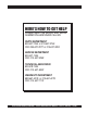
HERE'S HOW TO GET HELP PLEASE HAVE THE MODEL AND SERIAL NUMBER ON-HAND WHEN CALLING PARTS DEPARTMENT 800-427-1244 or 310-537-3700 FAX: 800-672-7877 or 310-637-3284 SERVICE DEPARTMENT 800-421-1244 FAX: 310- 537-4259 TECHNICAL ASSISTANCE 800-478-1244 FAX: 310- 631-5032 WARRANTY DEPARTMENT 888-661-4279, or 310-661-4279 FAX: 310- 537-1173 DCA-125SSJU SERIES (STANDARD)— PARTS AND OPERATION MANUAL— REV.
TABLE OF CONTENTS DCA-125SSJU & DCA-125SSJU2 AC GENERA TOR GENERATOR Here's How To Get Help .................................................... 3 Table Of Contents ............................................................. 4 Parts Ordering Procedures ............................................... 5 Specifications ................................................................... 6 Dimensions (Top, Side, Front) ........................................... 7 Safety Message Alert Symbols .................
PARTS ORDERING PROCEDURES When ordering parts, please supply the following information: ❒ ❒ ❒ ❒ ❒ ❒ ❒ Dealer account number Dealer name and address Shipping address (if different than billing address) Return fax number Applicable model number Quantity, part number and description of each part Specify preferred method of shipment: Note: Unless otherwise indicated by customer, all ✓ FedEx or UPS Ground orders are treated as “Standard Orders”, and will ✓ FedEx or UPS Second Day or Third Day ship within 24 hou
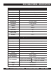
DCA-125SSJU SERIES — SPECIFICATIONS Table 1. Generator Specifications Model DCA-125SSJU/125SSJU2 Type Revolving field, self ventilated, drip proof single bearing Armature Connection Star with Neutral/Zig Zag Voltage 3-Phase 208, 220, 240, 416, 440, 480V switchable Voltage Single-Phase 120, 127, 139, 240, 254, 277V switchable Standby Output 137.5 KVA (110 KW) Prime Output 125 KVA (100 KW) Frequency 6 0 Hz Speed 1800 r pm Power Factor 0.
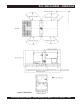
DCA-125SSJU SERIES — DIMENSIONS Figure 1. Dimensions DCA-125SSJU SERIES (STANDARD)— PARTS AND OPERATION MANUAL— REV.
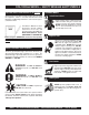
DCA-125SSJU SERIES — SAFETY MESSAGE ALERT SYMBOLS FOR YOUR SAFETY AND THE SAFETY OF OTHERS! Safety precautions should be followed at all times when operating this equipment. Failure to read and understand the Safety Messages and Operating Instructions could result in injury to yourself and others. NOTE This Owner's Manual has been developed to provide complete instructions for the safe and efficient operation of the MQ Power Model DCA125SSJU Series WHISPERWATT™ GENERATOR.
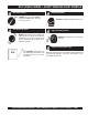
DCA-125SSJU SERIES — SAFETY MESSAGE ALERT SYMBOLS Accidental Starting ALWAYS place the engine ON/OFF switch in the OFF position, when the trowel is not in use. Over Speed Conditions NEVER tamper with the factory settings of the engine governor or settings. Personal injury and damage to the engine or equipment can result if operating in speed ranges above maximum allowable. Respiratory Hazard ALWAYS wear approved respiratory protection.
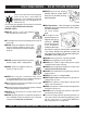
DCA-125SSJU SERIES — RULES FOR SAFE OPERATION ■ NEVER touch the hot exhaust manifold, muffler or cylinder. Allow Failure to follow instructions in this manual may these parts to cool before servicing lead to serious injury or even death! This engine or generator. equipment is to be operated by trained and qualified personnel only! This equipment is for industrial use only.
DCA-125SSJU SERIES — RULES FOR SAFE OPERATION . ■ ALWAYS make sure that electrical circuits are properly grounded per the National Electrical Code (NEC) and local codes before operating generator. Severe injury or death! by electrocution can result from operating an ungrounded generator. DANGER DANGER: ■ ALWAYS be sure the operator is familiar with proper safety precautions and operations techniques before using generator. ■ ALWAYS store equipment properly when it is not being used.
DCA-125SSJU SERIES — RULES FOR SAFE OPERATION ■ NEVER Run engine without air filter. Severe engine Battery damage may occur. The battery contains acids that can cause injury to the eyes ■ ALWAYS service air cleaner frequently to prevent engine and skin. To avoid eye irritation, always wear safety glasses. Use well insulated gloves when picking up the battery. Use malfunction.
DCA-125SSJU SERIES — RULES FOR SAFE OPERATION Towing Safety Precautions CAUTION: ■ Avoid sharp turns. ■ Trailer should be adjusted to a level position at all times when towing. Conform to Department of Transportation ■ Raise and lock trailer wheel stand in up position when transporting. (DOT) Safety Towing Regulations before towing generator. ■ DOT Requirements include the following: z Connect and test electric brake operation.
DCA-125SSJU SERIES — INSTALLATION Figure 2. Typical Generator Grounding Application PAGE 14 — DCA-125SSJU SERIES (STANDARD) — PARTS AND OPERATION MANUAL — REV.
DCA-125SSJU SERIES — INSTALLATION Outdoor Installation Install the generator in a area that is free of debris, bystanders, and overhead obstructions. Make sure the generator is on secure level ground so that it cannot slide or shift around. Also install the generator in a manner so that the exhaust will not be discharged in the direction of nearby homes. The installation site must be relatively free from moisture and dust. All electrical equipment should be protected from excessive moisture.
DCA-125SSJU SERIES — TOWING SAFTEY PRECAUTIONS Towing Safety Precautions CAUTION CAUTION: Check with your local county or state safety towing regulations before towing your generator. To reduce the possibility of an accident while transporting the generator on public roads, always make sure the trailer (Figure 4) that supports the generator and the towing vehicle are in good operating condition and both units are mechanically sound.
DCA-125SSJU SERIES — TRAILER SPECIFICATIONS 5. Frame Length - Measurement is from fender to fender ALWAYS make sure the trailer is in good 6. Jack Stand - Trailer support device with maximum pound requirement from the tongue of the trailer. operating condition. Check the tires for proper inflation and wear. Also check the 7. Coupler - Type of hitch used on the trailer for towing. 8. Tire Size - Indicates the diameter of the tire in inches wheel lug nuts for proper tightness. (10,12,14, etc.
DCA-125SSJU SERIES — TRAILER SPECIFICATIONS Table 2. Trailer Specifications MODEL APPLICATION FU E L C E LL BRAKE SYSTEM GVWR FRAME LENGTH FRAME WIDTH JACK STAND TRLR-10W SDW225, SGW250,TLW300 NO NO 1900LB S 96" 50" 800LB . FULL TILT WHEEL TRLR-10 D C A 10, TLG12, DCA15 NO NO 1900LB S 96" 50" 800LB . FULL TILT WHEEL TRLR-10XF DCA10, TLG12, D C A 15, TLW-300 52 GAL NO 1900LB S 96" 50" 800LB . FULL TILT WHEEL TRLR-225W WELDERS, D A 7000S S NO NO 2200LB S 85" 42" 800LB .
DCA-125SSJU SERIES — TRAILER SPECIFICATIONS Table 2. Specifications (Con't) MODEL COUPLER TIRES WHEELS AXLE HUBS SUSPENSION ELECTRICAL TRLR-10W 2" B A LL C LA S S 2 ADJUSTABLE 175-13C 13"X4.50" 2200# 2X 2 5 LUG 3 LE A F 4 WIRE LOOM W/ 4 POLE FLAT TRLR-10 2" B A LL C LA S S 2 ADJUSTABLE 175-13C 13"X4.5" 2200#2X 2 5 LUG 3 LE A F 4 POLE FLAT TRLR-10XF 2" B A LL C LA S S 2 ADJUSTABLE 175-13C 13"X4.
DCA-125SSJU SERIES — GENERATOR DECALS The DCA-125SSJU Series generator is equipped with a number of safety decals. These decals are provided for operator safety and maintenance information. The illustration below and on the preceding page show the decals as they appear on the machine. Should any of these decals become unreadable, replacements can be obtained from your dealer. PAGE 20 — DCA-125SSJU SERIES (STANDARD) — PARTS AND OPERATION MANUAL — REV.
DCA-125SSJU SERIES — GENERATOR DECALS DCA-125SSJU SERIES (STANDARD)— PARTS AND OPERATION MANUAL— REV.
DCA-125SSJU SERIES — GENERAL INFORMATION DCA-125SSJU Series Familiarization Generator The MQ Power DCA-125SSJU Series is a 100 kW generator (Figure 4) that is designed as a high quality portable (requires a trailer for transport) power source for telecom sites, lighting facilities, power tools, submersible pumps and other industrial and construction machinery.
DCA-125SSJU SERIES — MAJOR COMPONENTS Table 3. Generator Major Components ITEM NO. DESCRIPTION 1 Muffler Assembly 2 Engine Assembly 3 Enclosure Assembly 4 Generator Assembly 5 Output Terminal Assembly 6 Fuel Tank Assembly 7 Battery Assembly 8 Generator Control Panel Assembly 9 Engine Operating Panel Assembly DCA-125SSJU SERIES (STANDARD)— PARTS AND OPERATION MANUAL— REV.
DCA-125SSJU SERIES — GENERATOR CONTROL PANEL Figure 5. Generator Control Panel The definitions below describe the controls and functions of the DCA-125SSJU Series "Generator Control Panel " (Figure 5). 1. Main Circuit Breaker – This three-pole, 300 amp main breaker is provided to protect the UVWO output terminals from overload. 2. 3. 4. 5. 6. 7. AC Ammeter – Indicates the amount of current the load is drawing from the generator per leg selected by the ammeter phase-selector switch.
DCA-125SSJU SERIES — ENGINE OPERATING PANEL Figure 6. Engine Operating Panel Up To S/N 7500507 The definitions below describe the controls and functions of 6. the DCA-125SSJU Series "Engine Operating Panel " 7. (Figure 6), up to S/N 7500507. 1. 2. 3. 4. 5. Fuel Gauge - Indicates amount of diesel fuel available. Tachometer – Indicates engine speed in RPM’s for 60 Hz operation. This meter should indicate 1800 RPM’s when the rated load is applied.
DCA-125SSJU SERIES — ENGINE OPERATING PANEL Figure 7. Engine Operating Panel From S/N 7500508 PAGE 26 — DCA-125SSJU SERIES (STANDARD) — PARTS AND OPERATION MANUAL — REV.
DCA-125SSJU SERIES — ENGINE OPERATING PANEL The definitions below describe the controls and functions of the DCA-125SSJU2 " Engine Operating Panel " (Figure 7) from S/N 7500508 ~. 1. Panel Light – Normally used in dark areas or at night time. When activated, panel lights will illuminate. When the generator is not in use be sure to turn the panel light switch to the OFF position. 2. Panel Light Switch – When activated will turn on control panel light. 3. 4. 5.
DCA-125SSJU SERIES — OUTPUT TERMINAL PANEL FAMILIARIZATION Output Terminal Familiarization The “Output Terminal Panel ” (Figure 8) is provided with the following: z Three (3) 240V Output Receptacles, 50 amp z Three (3) Circuit Breakers 240V @50 amps z Two (2) 120V GFCI receptacles, 20 amp z Two (2) GFCI Circuit Breakers 120V@ 20 amps z One 300 Amp Main Circuit Breaker z Five (5) Output Terminal Lugs Output Terminal Panel The Output Terminal Panel ( Figure 8) shown below is located on the right-hand side (l
DCA-125SSJU SERIES — OUTPUT TERMINAL PANEL FAMILIARIZATION 120 VAC GFCI Receptacles There are two 120 VAC, 20 amp GFCI (Duplex Nema 5-20R) recepacles provided on the output terminal panel. These receptacles can be accessed in any voltage selector switch position. Each receptacle is protected by a 20 amp circuit breaker. These breakers are located directly above the GFCI receptacles. Remember the load output (current) of both GFCI receptacles is dependent on the load requirements of the UVWO terminals.
DCA-125SSJU SERIES — OUTPUT TERMINAL PANEL FAMILIARIZATION Connecting Loads Loads can be connected to the generator by the UVWO terminal lugs or the convienience receptacles. (See Figure 13). Make sure to read the operation manual before attempting to connect a load to the generator. Over Current Relay An over current relay (Figure 14) is connected to the main circuit breaker. In the event of an overload, both the circuit breaker and the over current relay may trip.
DCA-125SSJU SERIES — LOAD APPLICATION Single Phase Load Always be sure to check the nameplate on the generator and equipment to insure the wattage, amperage and frequency requirements are satisfactorily supplied by the generator for operating the equipment. Generally, the wattage listed on the nameplate of the equipment is its rated output.
DCA-125SSJU SERIES — GENERATOR OUTPUTS Generator Output Voltages Generator Amperage A wide range of voltages are available to supply voltage for Tables 7 and 8 describe the generator’s current output capamany different applications. Voltages are selected by using bility for both 1Ø-phase and 3Ø phase applications. the voltage selector switch (Figure 15). To obtain some of the voltages as listed in Table 6 (see below) will require a Table 7.
DCA-125SSJU SERIES — GENERATOR OUTPUTS/GAUGE READING GFCI Receptacle Load Capability The load capability of the GFCI receptacles is directly related to the voltage being supplied at either the UVWO terminals or the 3 twist lock auxilliary receptacles. Tables 9 and 10 show what amount of current is available at the GFCI receptacles when the UVWO terminals and twist lock receptacles are in use. Be careful that your load does not to exceed the available current capability at the receptacles.
DCA-125SSJU SERIES — OUTPUT TERMINAL PANEL CONNECTIONS UVWO Terminal Output Voltages 3Ø 208V/1Ø120V UVWO Terminal Output Voltages Various output voltages can be obtained using the UVWO 1. Place the voltage selector switch in the 3Ø 240/139 position as shown in Figure 24. output terminal lugs. The voltages at the terminals are dependent on the position of the Voltage Selector Switch and Use this position for the adjustment of the Voltage Regulator Control Knob. 3Ø-208 or 1Ø120V.
DCA-125SSJU SERIES — OUTPUT TERMINAL PANEL CONNECTIONS 3Ø 480/277 UVWO Terminal Output Voltages 1Ø 240V/120V UVWO Terminal Output Voltages 1. Place the voltage selector switch in the 3Ø 480/277 position as shown in Figure 27. 1. Place the voltage selector switch in the 1Ø 240/120 position as shown in Figure 30. Figure 27. Voltage Selector Switch 480/277V Three-Phase Position Figure 30. Voltage Selector Switch 240/120V Single-Phase Position 2.
DCA-125SSJU SERIES — PRE-SETUP Circuit Breakers Fuel Check To protect the generator from an overload, a 3-pole, 300 amp, main circuit breaker is provided to protect the UVW output terminals from overload. In addition two single-pole, 20 amp GFCI circuit breakers are provided to protect the GFCI receptacles from overload.Three 50 amp load circuit breakers have also been provided to protect the auxiliary receptacles from overload.
DCA-125SSJU SERIES — PRE-SETUP CAUTION: ALWAYS! fill trailer tank first with #2 diesel fuel, before filling secondary internal tank. Figure 35. Skid Type Fuel Tank System Refueling Procedure: DANGER: Diesel fuel and its vapors are dangerous to your health and the surrounding environment. Avoid skin contact and/or inhaling fumes. 1. Level Tanks – make sure fuel cells are level with the ground. Failure to do so will cause fuel to spill from the tank before reaching full capacity. See Figure 36.
DCA-125SSJU SERIES — PRE-SETUP 3. NEVER overfill trailer fuel tank – It is important to 5. read the trailer fuel gauge when filling trailer fuel tank. DO NOT wait for fuel to rise in filler neck. See Figure 38. Figure 38. Full Trailer Tank WARNING: DO NOT OVER-FILL fuel system. Leave room for fuel expansion . Fuel expands when heated. 4. Once the trailer tank is full, the secondary inner tank can be filled (See Figure 39). Notice how the trailer filler tube level rises when the internal tank is filled.
DCA-125SSJU SERIES — PRE-SETUP Coolant (Ethylane Glycol [Green] / Water — 50/50 mix) Use only drinkable tap water. If hard water or water with many impurities is used, the inside of the engine and radiator may become coated with deposits and cooling efficiency will be reduced. An anticorrosion additive added to the water will help prevent deposits and corrosion in the cooling system. See the engine manual for further details.
DCA-125SSJU SERIES — PRE-SETUP When connecting battery do the following: Battery This unit is of negative ground DO NOT connect in reverse. 1. NEVER connect the battery cables to the battery terminals when the ignition switch is in either the PreAlways maintain battery fluid level between the specified Heat, RUN, or START position. ALWAYS make sure marks. Battery life will be shortened, if the fluid level are not properly maintained.
DCA-125SSJU SERIES — GENERATOR START-UP PROCEDURE (MANUAL) WARNING: 2. Connect the load to the UVWO terminals or auxiliary receptacles as shown in Figure 46. These load The engine's exhaust contains harmful connection points can be found on the output terminal panel. To gain access to the UVWO terminals or other emissions. ALWAYS have adequate power receptacles, unlock the access cover and lift the ventilation when operating. Direct exhaust door. away from nearby personnel. 3.
DCA-125SSJU SERIES — GENERATOR START-UP PROCEDURE (MANUAL) 6. Press and hold the engine cold starting button (Figure 49) until the button illuminates (ON). 11. The generator's frequency meter (Figure 54) should be displaying the 60 cycle output frequency in HERTZ. Figure 49. Cold Starting Button Figure 54. Frequency Meter (Hz) 7. Place the voltage selector switch in the desired voltage position (Figure 50). Figure 50. Voltage Selector Switch 12.
DCA-125SSJU SERIES — GENERATOR START-UP PROCEDURE (MANUAL) 15. The coolant temperature gauge (Figure 59) will indicate the coolant temperature. Under normal operating conditions the coolant temperature should be between 165 and 215 degrees Fahrenheit (Green Zone). 18. Observe the generator's ammeter (Figure 62) and verify it reads the anticipated amount of current with respect to the load. The ammeter will only display a current reading if a load is in use. Figure 59. Coolant Temperature Gauge Figure 62.
DCA-125SSJU SERIES — GENERATOR START-UP PROCEDURE (MANUAL) WARNING: 23. Set engine speed switch to “LOW ” (Figure 65). The engine's exhaust contains harmful emissions. ALWAYS have adequate ventilation when operating. Direct exhaust away from nearby personnel. Figure 65. Engine Speed Switch (Low) Before Starting Engine Operating Panel S/N 7500508~ CAUTION: NEVER! manually start the engine with the main, GFCI or auailliary circuit breakers in the ON (closed) position.
DCA-125SSJU SERIES — GENERATOR START-UP PROCEDURE (AUTO MODE) DANGER: Before connecting this generator to any building’s electrical system, a licensed electrician must install an isolation (transfer) switch. Serious injury or death may result without this transfer switch. CAUTION: CAUTION: 30. Place the Off/Manual/Auto switch (Figure 70) in the “AUTO“ position . When connecting the generator to a isolation (transfer) switch, ALWAYS have power applied to the generator's internal battery charger.
DCA-125SSJU SERIES — GENERATOR SHUT-DOWN PROCEDURE Shutdown Procedure - Ignition Switch (Up to S/N 7500507) To shutdown the generator use the following procedure: 1. Place both the MAIN, GFCI and LOAD circuit breakers as shown in Figure 45 to the "OFF position". 2. Place the engine throttle control in the “LOW” position (Figure 71). Figure 71. Engine Throttle Control (Low) 3. Let the engine cool by running it for 3-5 minutes with no load applied. 4.
DCA-125SSJU SERIES — MAINTENANCE TABLE 14.
DCA-125SSJU SERIES — MAINTENANCE Air Removal If air enters the fuel injection system of a diesel engine, starting becomes impossible. After running out of fuel, or after disassembling the fuel system, bleed the system according to the following procedure. To restart after running out of fuel, turn the switch to the “ON” position for 15-30 seconds. Try again, if needed. This unit is equipped with an automatic air bleeding system.
DCA-125SSJU SERIES — MAINTENANCE Jacket Water Heater and Internal Battery Charger 120 VAC Input Receptacles (OPTIONAL) This generator is equipped with two 120 VAC, 20 amp input receptacles located on the output terminal panel. The purpose of these receptacles is to provide power via commercial power to the jacket water heater and internal battery charger. These receptacles will ONLY function when commercial power has been supplied to them (Figure 75).
DCA-125SSJU SERIES — TRAILER BRAKES MAINTENANCE Brakes Trailer brakes should be inspected the first 200 miles of operation. This will allow the brake shoes and drums to seat properly. After the first 200 mile interval, inspect the brakes every 3,000 miles. If driving over rough terrain, inspect the brakes more frequently. Figure 74 displays the major hydraulic surge brake components that will require inspection and maintenance.
DCA-125SSJU SERIES — TRAILER MAINTENANCE Tires/Wheels/Lug Nuts Tires and wheels are a very impor tant and critical components of the trailer. When specifying or replacing the trailer wheels it is important the wheels, tires, and axle are properly matched. CAUTION: Suspension The leaf suspension springs and associated components (Figure 77) should be visually inspected every 6,000 miles for signs of excessive wear, elongation of bolt holes, and loosening of fasteners.
DCA-125SSJU SERIES — TRAILER MAINTENANCE Lug Nut Torque Requirements It is extremely important to apply and maintain proper wheel mounting torque on the trailer. Be sure to use only the fasteners matched to the cone angle of the wheel. Proper procedure for attachment of the wheels is as follows: 1. Start all wheel lug nuts by hand. 2. Torque all lug nuts in sequence. See Figure 78. DO NOT torque the wheel lug nuts all the way down. Tighten each lug nut in 3 separate passes as defined by Table 18. 3.
DCA-125SSJU SERIES — TRAILER WIRING DIAGRAM Figure 79. Trailer/Towing Vehicle Wiring Diagram DCA-125SSJU SERIES (STANDARD)— PARTS AND OPERATION MANUAL— REV.
DCA-125SSJU SERIES — GENERATOR WIRING DIAGRAM Figure 80. Generator Wiring Diagram PAGE 54 — DCA-125SSJU SERIES (STANDARD) — PARTS AND OPERATION MANUAL — REV.
DCA-125SSJU SERIES — ENGINE WIRING DIAGRAM (IGNITION SWITCH) Figure 81. Engine Wiring Diagram(Ignition Switch) DCA-125SSJU SERIES (STANDARD)— PARTS AND OPERATION MANUAL— REV.
DCA-125SSJU SERIES — ENGINEWIRING DIAGRAM (ENGINE CONTROLLER) Figure 82. Engine Wiring Diagram (Engine Controller) PAGE 56 — DCA-125SSJU SERIES (STANDARD) — PARTS AND OPERATION MANUAL — REV.
NOTE PAGE DCA-125SSJU SERIES (STANDARD)— PARTS AND OPERATION MANUAL— REV.
DCA-125SSJU SERIES — TROUBLESHOOTING (ENGINE) Practically all breakdowns can be prevented by proper handling and maintenance inspections, but in the event of a breakdown, use the table shown below and on the next page for diagnosis based on the Engine Troubleshooting (Table 19). If the problem cannot be remedied, consult our company's business office or service plant. TABLE 19. ENGINE TROUBLESHOOTING SYMPTOM Engine does not star t. POSSIBLE PROBLEM SOLUTION No fuel? Replenish fuel.
DCA-125SSJU SERIES — TROUBLESHOOTING (ENGINE) TABLE 19. ENGINE TROUBLESHOOTING (CONTINUED) SYMPTOM Engine revolution is not smooth. Either white or blue exhaust gas is observed. Either black or dark gray exhaust gas is observed. Deficient output. POSSIBLE PROBLEM SOLUTION Fuel filter clogged or dir ty? Clean or change. Air cleaner clogged? Clean or change. Fuel leak due to loose injection pipe retaining nut? Tighten nut. Injection pump malfunctioning? Repair or replace.
DCA-125SSJU SERIES — TROUBLESHOOTING (GENERATOR) Practically all breakdowns can be prevented by proper handling and maintenance inspections, but in the event of a breakdown, use the table shown below for diagnosis based on the Generator Troubleshooting (Table 20). If the problem cannot be remedied, consult our company's business office or service plant. TABLE 20.
DCA-125SSJU SERIES — TROUBLESHOOTING (MPEC) Practically all breakdowns can be prevented by proper handling and maintenance inspections, but in the event of a breakdown, use the table shown below for diagnosis based on the MPEC Troubleshooting (Table 21). If the problem cannot be remedied, consult our company's business office or service plant. TABLE 21. ENGINE CONTROLLER TROUBLESHOOTING Sympton Low oil pressure light is on. Low coolant level light is on. High coolant temper ture light is on.
EXPLANATION OF CODE IN REMARKS COLUMN How to read the marks and remarks used in this parts book. Items Found In the “Remarks” Column Serial Numbers-Where indicated, this indicates a serial number range (inclusive) where a particular part is used. Model Number-Where indicated, this shows that the corresponding part is utilized only with this specific model number or model number variant.
DCA-125SSJU SERIES — SUGGESTED SPARE PARTS DCA-125SSJU & DCA-125SSJU2 W/JOHN DEERE 6080TF250 DIESEL ENGINE 1 TO 3 UNITS Qty.
DCA-125SSJU SERIES — NAMEPLATE AND DECALS NAMEPLATE AND DECALS PAGE 64 — DCA-125SSJU SERIES (STANDARD) — PARTS AND OPERATION MANUAL — REV.
DCA-125SSJU SERIES — NAMEPLATE AND DECALS NAMEPLATE AND DECALS NO. PART NO. PART NAME QTY. REMARKS 1 M1550000204 DECAL, NOTE .....................................................1 .............. M15000020 2 M1550000703 DECAL, AUXILLIARY OUTPUT........................... 1 .............. M15000070 3 M3550000004 DECAL, NOTE .....................................................1 .............. M35000000 4 M3550000102 DECAL, GENERATOR CONTROL .......................1 ..............
DCA-125SSJU SERIES — GENERATOR ASSY. GENERATOR ASSY. PAGE 66 — DCA-125SSJU SERIES (STANDARD) — PARTS AND OPERATION MANUAL — REV.
DCA-125SSJU SERIES — GENERATOR ASSY. GENERATOR ASSY. NO. PART NO. 1 C0110000002 1-1 1-2 8131070013 1-3 8131611014 1-4 8131015003 1-5 0012112035 1-6 0042612000 1-7 8101026013 1-8 0601821349 1-9 0601822601 1-10 8001020004 1-11 8001020504 1-12 0010110020 1-13 0040010000 1-14 0601000209 1-15 0071906312 2 8131340213 3 0845041804 4 8131315202 5 8101350013 6 0012110060 7 0042610000 8 031110160 9 0010112035 10 0040012000 11 031112230 12 8131310104 13 8131312204 14 8131331003 15 0105050616 PART NAME QTY.
DCA-125SSJU SERIES — GENERATOR ASSY. (CONT.) GENERATOR ASSY. (CONT.) PAGE 68 — DCA-125SSJU SERIES (STANDARD) — PARTS AND OPERATION MANUAL — REV.
DCA-125SSJU SERIES — GENERATOR ASSY. (CONT.) GENERATOR ASSY. (CONT.) NO. PART NO. PART NAME QTY. REMARKS 16 8101333003 COVER, END BRACKET 1 17 0010106030 HEX. HEAD BOLT 2 18 0040006000 LOCK WASHER 2 19 952404470 PLAIN WASHER ............................... 2 ......... REPLACES 0041206000 20 M3163400003 COUPLING RING 1 21 0013904044 HEX. HEAD BOLT ............................ 8 ......... S/N 7500001 TO 7500242 21 0343204150 HEX. HEAD BOLT ............................ 8 .........
DCA-125SSJU SERIES — CONTROL BOX ASSY. CONTROL BOX ASSY. PAGE 70 — DCA-125SSJU SERIES (STANDARD) — PARTS AND OPERATION MANUAL — REV.
DCA-125SSJU SERIES — CONTROL BOX ASSY. CONTROL BOX ASSY. NO. PART NO.
DCA-125SSJU SERIES — CONTROL BOX ASSY. (CONT.) CONTROL BOX ASSY. (CONT.) PAGE 72 — DCA-125SSJU SERIES (STANDARD) — PARTS AND OPERATION MANUAL — REV.
DCA-125SSJU SERIES — CONTROL BOX ASSY. (CONT.) CONTROL BOX ASSY. (CONT.) NO. PART NO. PART NAME QTY. REMARKS 29 0601808953 AC AMMETER, 260240LSLS1JCA .............1 ............ S/N 7500001 TO 7500842 29 0601808988 AC AMMETER, ACF-6 - 200A,0-400A/5A ... 1 ............ S/N 7500843~ 30 0601801040 CHANGE-OVER SWITCH, AMMETER ....... 1 ............ SL2AS 31 0601806813 AC VOLTMETER, 260244SJSJ1 .................1 ............ S/N 7500001 TO 7500842 31 0601806859 AC AMMETER, SCF-6 0-600V ....................1 ...
DCA-125SSJU SERIES — ENGINE AND RADIATOR ASSY. ENGINE AND RADIATOR ASSY. PAGE 74 — DCA-125SSJU SERIES (STANDARD) — PARTS AND OPERATION MANUAL — REV.
DCA-125SSJU SERIES — ENGINE AND RADIATOR ASSY. ENGINE AND RADIATOR ASSY. NO. PART NO.
DCA-125SSJU SERIES — ENGINE AND RADIATOR ASSY. (CONT.) ENGINE AND RADIATOR ASSY. (CONT.) PAGE 76 — DCA-125SSJU SERIES (STANDARD) — PARTS AND OPERATION MANUAL — REV.
DCA-125SSJU SERIES — ENGINE AND RADIATOR ASSY. (CONT.) ENGINE AND RADIATOR ASSY. (CONT.) NO. PART NO. PART NAME QTY. REMARKS 44 0602021165 O-RING .......................................... 1 ........... S/N 7500001 TO 7500307 45 0602022561 90o ELBOW .................................... 1 ........... 3398210-10+ 46 0602022562 UNION, 10WTXWLNS.................... 1 ........... S/N 7500001 TO 7500307 47 0602022792 SWIVEL, 306821010 ...................... 1 ........... S/N 7500001 TO 7500307 48 0602021070 CAP .
DCA-125SSJU SERIES — ENGINE OPERATING PANEL ASSY. ENGINE OPERATING PANEL ASSY. S/N7500001 TO S/N 7500507 S/N 7500508~ PAGE 78 — DCA-125SSJU SERIES (STANDARD) — PARTS AND OPERATION MANUAL — REV.
DCA-125SSJU SERIES — ENGINE OPERATING PANEL ASSY. ENGINE OPERATING PANEL ASSY. NO. PART NO. PART NAME QTY. REMARKS 1 M1354300304 SLIDE LEVER .............................................1 ............ S/N 7500001 TO 7500507 2 M9320000004 KNOB ..........................................................1 ............ S/N 7500001 TO 7500507 3 0036003000 HEX. NUT ....................................................1 ............ S/N 7500001 TO 7500507 4 0605804150 SPRING .........................................
DCA-125SSJU SERIES — OUTPUT TERMINAL ASSY. OUTPUT TERMINAL ASSY. PAGE 80 — DCA-125SSJU SERIES (STANDARD) — PARTS AND OPERATION MANUAL — REV.
DCA-125SSJU SERIES — OUTPUT TERMINAL ASSY. OUTPUT TERMINAL ASSY. NO. PART NO. PART NAME QTY. REMARKS 1 M3230700003 TERMINAL PANEL 1 2 M9220100304 OUTPUT TERMINAL BOLT 5 3 M9220100404 TIE BOLT 5 4 0039316000 HEX. NUT 10 5 0040016000 LOCK WASHER 15 6 0041416000 PLAIN WASHER 20 7 0012108035 HEX. HEAD BOLT .................................... 5 .............. REPLACES 0016908035 8 M3236100303 TERMINAL COVER .................................. 1 .............. S/N 7500001 TO 7500307 8 M3236100313 TERMINAL COVER .
DCA-125SSJU SERIES — BATTERY ASSY. BATTERY ASSY. PAGE 82 — DCA-125SSJU SERIES (STANDARD) — PARTS AND OPERATION MANUAL — REV.
DCA-125SSJU SERIES — BATTERY ASSY. BATTERY ASSY. NO. PART NO. 1 0602220196 2 M9310500404 3 M9103000504 4 0602220921 5 0040006000 6 M3346900004 7 M3346900104 8 9 0017112025 9 0040512000 10 0017110020 10 0040510000 PART NAME QTY. REMARKS BATTERY ....................................................1 ............ 4D-2 BATTERY SHEET 1 BATTERY BAND 1 BATTERY BOLT SET 2 LOCK WASHER 2 BATTERY CABLE 1 BATTERY CABLE 1 CABLE .........................................................1 ............ MAKE LOCALLY HEX.
DCA-125SSJU SERIES — MUFFLER ASSY. MUFFLER ASSY. PAGE 84 — DCA-125SSJU SERIES (STANDARD) — PARTS AND OPERATION MANUAL — REV.
DCA-125SSJU SERIES — MUFFLER ASSY. MUFFLER ASSY. NO. PART NO. 1 M3330100002 1 0602300167 2 012210025 3 M3333000303 4 0602325066 5 M3333200004 6 014210040 7 M33330400304 8 M3330400403 9 011008020 10 0602326061 PART NAME QTY. REMARKS MUFFLER ....................................................1 ............ S/N 7500001 TO 7500072 MUFFLER ....................................................1 ............ S/N 7500073~ HEX. HEAD BOLT .......................................4 ............
DCA-125SSJU SERIES — FUEL TANK ASSY. FUEL TANK ASSY. PAGE 86 — DCA-125SSJU SERIES (STANDARD) — PARTS AND OPERATION MANUAL — REV.
DCA-125SSJU SERIES — FUEL TANK ASSY. FUEL TANK ASSY. NO. PART NO. 1 M3363000202 1-1 0605505070 2 M3363200204 3 M9310500104 4 0016908020 5 037908000 5 0207308000 5 0041208000 6 0222100660 7 M9200000003 8 M9200200004 9 0150000018 10 0016906020 11 M1363400104 12 0605515198 13 0602042420 14 0602042601 15 0191300450 16 0191301802 17 0191302200 18 0605515189 19 0605515109 20 0602220911 PART NAME QTY. REMARKS FUEL TANK 1 CAP, FUEL TANK 1 TANK BAND 2 SUPPORTERsheet 4 HEX. HEAD BOLT 2 HEX NUT ......................
DCA-125SSJU SERIES — ENCLOSURE ASSY. ENCLOSURE ASSY. ADD THE FOLLOWING DIGITS AFTER THE PART NUMBER WHEN ORDERING ANY PAINTED PANEL TO INDICATE COLOR OF UNIT: 5 -BLACK 1-ORANGE 6 -CATERPILLAR YELLOW 2-WHITE 3 -SPECTRUM GRAY 7 -CATO GOLD 4 -SUNBELT GREEN THE SERIAL NUMBER MAY BE REQUIRED. PAGE 88 — DCA-125SSJU SERIES (STANDARD) — PARTS AND OPERATION MANUAL — REV.
DCA-125SSJU SERIES — ENCLOSURE ASSY. ENCLOSURE ASSY. NO. PART NO.
DCA-125SSJU SERIES — ENCLOSURE ASSY. (CONT.) ENCLOSURE ASSY. (CONT.) ADD THE FOLLOWING DIGITS AFTER THE PART NUMBER WHEN ORDERING ANY PAINTED PANEL TO INDICATE COLOR OF UNIT: 5 -BLACK 1-ORANGE 6 -CATERPILLAR YELLOW 2-WHITE 3 -SPECTRUM GRAY 7 -CATO GOLD 4 -SUNBELT GREEN THE SERIAL NUMBER MAY BE REQUIRED. PAGE 90 — DCA-125SSJU SERIES (STANDARD) — PARTS AND OPERATION MANUAL — REV.
DCA-125SSJU SERIES — ENCLOSURE ASSY. (CONT.) ENCLOSURE ASSY. (CONT.) NO. PART NO. PART NAME QTY. REMARKS 25 M3463100203 ROOF PANEL 1 25 M3493500203 ACOUSTIC SHEET 1 26 M3463200102 ROOF PANEL 1 26 M3493500303 ACOUSTIC SHEET 1 27 M3463500104 OVER COVER, FRONT FRAME 1 28 011008020 HEX. HEAD BOLT ....................................37 ............. REPLACES 0016908020 29 M9310000103 ENCLOSURE CAP 1 30 M1483600204 CHAIN ASSY. 1 31 M3453200102 SPLASHER PANEL ................................... 1 .............
DCA-125SSJU SERIES — RUBBER SEAL ASSY. RUBBER SEAL ASSY. PAGE 92 — DCA-125SSJU SERIES (STANDARD) — PARTS AND OPERATION MANUAL — REV.
DCA-125SSJU SERIES — RUBBER SEAL ASSY. RUBBER SEAL ASSY. NO. PART NO.
Effective: October 1, 2002 PAYMENT TERMS TERMS AND CONDITIONS OF SALE — PARTS 5. Parts must be in new and resalable condition, in the original Multiquip package (if any), and with Multiquip part numbers clearly marked. 6. The following items are not returnable: Terms of payment for parts are net 10 days. FREIGHT POLICY All parts orders will be shipped collect or prepaid with the charges added to the invoice. All shipments are F.O.B. point of origin.
NOTE PAGE DCA-125SSJU SERIES (STANDARD)— PARTS AND OPERATION MANUAL— REV.
OPERATION AND PARTS MANUAL HERE'S HOW TO GET HELP PLEASE HAVE THE MODEL AND SERIAL NUMBER ON-HAND WHEN CALLING PARTS DEPARTMENT 800-427-1244 or 310-537-3700 FAX: 800-672-7877 or 310-637-3284 SERVICE DEPARTMENT 800-421-1244 FAX: 310- 537-4259 TECHNICAL ASSISTANCE 800-478-1244 FAX: 310- 631-5032 WARRANTY DEPARTMENT 888-661-4279, or 310-661-4279 FAX: 310- 537-1173 MULTIQUIP INC.. PARTS DEPARTMENT: 18910 WILMINGTON AVE.