APPLICATION & INSTALLATION MANUAL MQ POWER © COPYRIGHT 2007, MQ PPOWER Industrial Generator Set Application & Installation Manual Revision #4 (09/07/07) MQPOWER A Division of Multiquip Inc. POST OFFICE BOX 6254 CARSON, CA 90749 310-537-3700 • 800-883-2551 FAX: 310-632-2656 E-MAIL: mqpower@multiquip.com WWW: www.mqpower.
PAGE 2 — INDUSTRIAL GENERATOR SETS — APPLICATION & INSTALLATION MANUAL — REV.
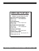
HERE'S HOW TO GET HELP PLEASE HAVE THE MODEL AND SERIAL NUMBER ON-HAND WHEN CALLING MULTIQUIP’S MAIN PHONE NUMBERS 800-421-1244 FAX: 310-537-3927 310-537-3700 PARTS DEPARTMENT 800-427-1244 FAX: 310-637-3284 310-537-3700 MQ POWER SERVICE DEPARTMENT 800-835-2551 FAX: 310-638-8046 310-537-3700 TECHNICAL ASSISTANCE 800-478-1244 FAX: 310-631-5032 WARRANTY DEPARTMENT 800-421-1244, EXT. 279 FAX: 310-537-1173 310-537-3700, EXT. 279 INDUSTRIAL GENERATOR SETS — APPLICATION & INSTALLATION MANUAL — REV.
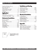
TABLE OF CONTENTS Proposition 65 California Warning ............................. 2 Here's How To Get Help ............................................ 3 Table Of Contents ..................................................... 4 Safety Message Alert Symbols .............................. 6-7 Important Safety Instructions ............................... 8-13 Introduction ............................................................. 14 Installation Overview ..........................................
NOTES PAGE INDUSTRIAL GENERATOR SETS — APPLICATION & INSTALLATION MANUAL — REV.
SAFETY MESSAGE ALERT SYMBOLS FOR YOUR SAFETY AND THE SAFETY OF OTHERS! Safety precautions should be followed at all times when installing or operating this equipment. Failure to read and understand the Safety Messages and Installation Instructions could result in injury to yourself and others. This genset Installation Manual has been developed to provide complete instructions for the safe NOTE implementation of MQ Power Gensets for field installation.
SAFETY MESSAGE ALERT SYMBOLS Accidental Starting ALWAYS place the ignition switch or genset starting device in the OFF position, remove key and/or disconnect the battery before servicing the engine or equipment. Over Speed Conditions NEVER tamper with the factory settings of the engine governor or settings. Personal injury and damage to the engine or equipment can result if operating in speed ranges above maximum allowable.
IMPORTANT SAFETY INSTRUCTIONS SAVE THESE INSTRUCTIONS — This manual contains important safety instructions for MQ Power Industrial generators that should be followed during installation, operation, and maintenance of the engine-generator set. Failure to follow instructions in this manual may lead to serious injury or even death! This equipment is to be operated by trained and qualified personnel only! This equipment is for industrial use only.
IMPORTANT SAFETY INSTRUCTIONS GENERAL SAFETY RADIATOR ■ DO NOT touch or open any of the components mentioned below while the generator is running. Always allow sufficient time for the engine and generator to cool before performing maintenance. ■ NEVER touch output terminals during operation. This is extremely dangerous. Always stop the machine and disconnect the battery when contact with the output terminals is necessary. 1.
IMPORTANT SAFETY INSTRUCTIONS Operation Safety ■ ALWAYS be sure the operator is familiar with proper safety precautions and operations techniques before using generator. ■ In emergencies always know the location of the nearest phone or keep a phone on the job site. Also know the phone numbers of the nearest ambulance, doctor and fire department. This information will be invaluable in the case of an emergency. ■ DO NOT allow unauthorized people near equipment.
IMPORTANT SAFETY INSTRUCTIONS Battery Safety The battery is a major component of the engine-generator set. The genset will not start without a properly maintained battery. Disconnecting the battery prevents the engine from starting. Always observe the following safety guidelines when interaction with the battery is necessary. Servicing of batteries should be performed by authorized personnel only. 1. Wear full eye protection and protective clothing, including rubber gloves and boots when handling a battery.
IMPORTANT SAFETY INSTRUCTIONS Fire Protection The design, selection, and installation of fire protection systems is beyond the scope of this manual because of the wide range of factors to consider. In general, every possible measure should be taken to prevent fire hazards and to protect property and people. Consider the following: ■ A protection system must comply with the requirements of the authority having jurisdiction. This could include the building inspector, fire marshal, or insurance carrier.
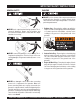
IMPORTANT SAFETY INSTRUCTIONS Lifting the Generator Set Transporting ■ Before lifting, make sure the generator's lifting devices are secure and that there is no apparent damage to the generator itself (loose screws, nuts and bolts). If any part is loose or damaged, please take corrective action before lifting. ■ Always drain fuel prior to lifting. ■ Always make sure crane or lifting device has been properly secured to the hook of guard frame on generator.
INTRODUCTION Introduction Engine-Generator sets provide emergency power in the event of utility power failure, provide power where utility power is not available and can provide an alternative power means in areas where utility power may be more expensive.
INSTALLATION OVERVIEW Overview Selection and Application These installation recommendations apply to typical installations with standard model gensets. Whenever possible, these recommendations also cover factory designed options or modifications. However, because of the large amount of variables involved with any installation, it is not possible to provide specific recommendations for every possible situation.
INSTALLATION OVERVIEW Cold Climates and Derating Factors Extreme temperature and high elevation effect the efficiency of the engine-generator set. Always take into account derating factors of climate and elevation when sizing a generator set. Use Premium No.1-D Grade diesel fuel when the ambient temperature is below freezing. Fuel heating may be required to prevent fuel filters from clogging when temperatures fall below the cloud point of the fuel at approximately 20°F (-6°C) for No.
GENSET SIZING The use of closed-transition autotransformer starters for reduced voltage starting of large motor loads will reduce the size of the generator set required relative to across-the-line starting. Resistor-type reduced-voltage motor starting may actually increase the size of the generator set required due to high starting power factors. Wound rotor motors are the easiest type of motor for a generator set to start.
GENSET SIZING Generator Set Sizing Calculations (Continued) Step 2. Create a Generator Set Worksheet a. When creating a worksheet, number a worksheet for each sequenced load step. The number block is in the upper right hand corner of the worksheet. Worksheet #1 will coincide with Load Step #1, Worksheet #2 will coincide with Load Step #2, and etc.. The step sequence guidelines will provide additional information to be followed here.
GENSET SIZING Generator Set Sizing Worksheet L o a d S te p # 1 Individual Load Characteristics SkVA SkW RkVA RkW GkW Load Step Totals QTY skVA skW RkVA Rkw Gkw Enter RkW total from previous load step ---> — Load Enter RkVA, RkW, and GkW totals from previous load step -# — — -> — 755.- 228f 178f 163.8f 163.8e1. 377.6a 113.3b 89d 81.9c 81.9e 2 ,f 2f 3. — — — — — 1 10.5g 10g 10.5g 10g 10e — — — — — — — — Load Step Totals --------------------------> 765.7 — 238 — — 188.5 173.
GENSET SIZING Generator Set Sizing Calculations (Continued) Step 3. Enter Individual Load Characteristics a. Calculate the values for SkVA, SkW, RkVA, and RkW and then enter the values on the worksheets. See determining load characteristics on page 22 for instructions on how to calculate the values for various types of loads. b. If the load quantity (QTY) is one, enter the values for SkVA, SkW, RkVA, and RkW directly onto the columns under the load step totals heading. c.
GENSET SIZING Generator Set Sizing Calculations (Continued) Step 5. Select a Generator Set a. Establish the minimum size required i. At this point the addition of future loads should be considered. The RkW and RkVA values that were highlighted or circled in Step 4 (previous page) should be multiplied by a factor representing your best judgement. ii.
GENSET SIZING — DETERMINING LOAD CHARACTERISTICS Determining Load Characteristics Lighting For all types of lighting loads: RkW = The sum of the rated watts of all lamps and ballasts. Single-Phase Induction Motor For 1Ø motors, use the SkVA, SkW, RkVA, and RkW values in Table 4 below that correspond to the motor nameplate horsepower and type. Typical ballast wattages are defined by Table 2 below: Table 2.
GENSET SIZING — DETERMINING LOAD CHARACTERISTICS Three-Phase Induction Motors Calculate RkW as follows: If EFF (motor running efficiency) of the motor is not known, refer to Table 5 and use the value corresponding to the motor horsepower. Calculate RkVA as follows: If RPF (running power factor) is unknown, refer to Table 5 and use the value corresponding to the motor horsepower. Calculate SkVA as follows: 1.
GENSET SIZING — DETERMINING LOAD CHARACTERISTICS Determining Load Characteristics (continued) 5. If reduced voltage motor starting is used, determine SkVA as in Steps 1, 2, 3, or 4 on previous page, and then multiply the value by the appropriate multiplying factor in Table 5. Use the following formula: Calculate SkW as follows: 1. If SPF (Starting Power Factor) is unknown, refer to Table 4 on page 22 and use the value corresponding to the motor horsepower.
GENSET SIZING — DETERMINING LOAD CHARACTERISTICS Three Phase NEMA Motor Code Table Table 7 lists the 3Ø motor starting kVA, starting power factor, and motor factors. Do not confuse the NEMA (National Electrical Manufacturers Association) motor Code and design letters. The code letter refers to the ratio of locked rotor kVA to HP, whereas the design letter refers to the ratio of torque to speed. HP A B 1/4 0.5 0.8 1/2 1.0 1.7 3/4 1.5 2.
GENSET SIZING — DETERMINING LOAD CHARACTERISTICS Synchronous Motors Although starting requirements for synchronous motors are lower, it is recommended to determine starting requirements in the same manner as induction motors previously covered. Static UPS Uninterrupted power supplies are nonlinear loads for which a calculation of GkW will be made, in addition to RkW, RkVA, SkW, and SkVA.
ENVIRONMENTAL CONSIDERATIONS — dB(A) Noise Consideration Because noise effects the surrounding environment, it is important to consider noise factors when installing a genset. The following is a brief approach to evaluating noise sources and noise level reduction. Noise requires a source, a path, and a receiver. In a standby system, the genset is the source, the path is air or air and a structure which transmits the noise vibrations, and the receiver is a person in the vicinity (including the operator).
ENVIRONMENTAL CONSIDERATIONS — dB(A) Comparison Chart dB(A) Figure 2 below provides a comparison of dB(A) levels for daily noises and the typical range of generator sets. Open generator sets are unhoused units where the path of noise is unobstructed. An acoustic housing encloses the genset to impede and absorb the path of noise. For applications that require even quieter operation, see the WhisperWatt™ product line for dB(A) levels as low as 62.
ENVIRONMENTAL CONSIDERATIONS — dB(A) Adding Additional Sound Sources The noise level at a given location is the sum of the noise levels from all sources, including reflecting sources. For example, the noise level in a free field along side of two identical generator sets would be double the noise level of either set when both sets are running. A doubling of the noise level is represented as an increase of approximately 3 dB(A).
ENVIRONMENTAL CONSIDERATIONS — dB(A) Effects of Distance As the distance between a noise source and receiver increases, the sound level decreases. If a second sound measurement is taken twice as far from the source, the second reading will be approximately 6 dB(A) less than the first reading.
ENVIRONMENTAL CONSIDERATIONS — dB(A) Reducing Noise Structure-Borne Noise Structure-borne noise is transmitted or generated as vibrations in structures. Vibrating structures create sound pressure waves (noise) in the surrounding air. Connections to a genset can cause vibrations in the building structure, creating noise. Typically, these include the skid anchors, radiator discharge air duct, exhaust piping, coolant piping, fuel lines, and wiring conduit.
ENVIRONMENTAL CONSIDERATIONS — dB(A) Acoustic Material Consider the following when selecting acoustic material: 1. DO NOT use fiberglass as an acoustic material. Fiberglass is a poor selection of acoustic material because of its low density, poor flame retardant, and poor cleanability. 2. Foam is least likely to deteriorate due to abrasion and has good aesthetics. However, foam is difficult to clean and not all foams are fire retardant. 3.
MOUNTING FOUNDATION Mounting Mounting on a Vibration Isolating Foundation Mounting the generator set is a critical part of the installation. A proper foundation must be able to support the weight of the generator set and its accessories, resist dynamic loads, and not transmit excessive noise and vibration. Foundations can be located on the floor, roof, indoors, or outdoors. Generator sets are typically mounted on a steel skid that provides support.
MOUNTING FOUNDATION Mounting Foundation Figure 6 below shows the typical foundation installation. Figure 7 below shows the typical footing on a foundation in soil with a low load bearing capacity. Figure 6. Typical Foundation Figure 7. Typical Footing PAGE 34 — INDUSTRIAL GENERATOR SETS — APPLICATION & INSTALLATION MANUAL — REV.
MOUNTING THE GENERATOR SET General Information Generator set installations must be engineered so the generator set will function properly under the expected load conditions. Use these instructions as a general guide only. Follow the instructions of the consulting engineer when locating or installing any components. The complete installation must comply with all local, state, and federal building codes, fire ordinances, and other applicable regulations.
MOUNTING — VIBRATION ISOLATORS Vibration Isolators Installation and Adjustment Procedure 1. Place the vibration isolators on the genset support structure. The isolators should be shimmed or grouted to ensure that all of the isolator bases are within 0.25 inch (6 mm) elevation of each other. The surface the isolator bases rest on must also be flat and level. (See Figure 9 to the right.) 2. Loosen the snubber lock nuts so that the top plate of the isolator is free to move vertically and horizontally.
MECHANICAL INSTALLATION — FUEL SYSTEM (DIESEL) MECHANICAL CONNECTIONS Introduction After considering all applicable codes and laws and finding a suitable location site for the generator set, the installer should consider the mechanical connections that will be necessary to make during installation.
MECHANICAL INSTALLATION — FUEL SYSTEM (DIESEL) Subbase Tank Base mounted or subbase fuel tanks are used to store fuel directly underneath the engine-generator set, eliminating the need for a remote main fuel supply tank and/or auxiliary fuel transfer pumps. This mounting arrangement offers the convenience of having a fuel supply tank mounted at the generator. These tanks are designed to be contained in a rectangular base on which the engine-generator set is mounted.
MECHANICAL INSTALLATION — FUEL SYSTEM (DIESEL) Diesel Fuel Supply Consider the following when installing a diesel fuel supply system: Fuel supply tank construction, location, installation, venting, piping, testing, and inspection must comply with all applicable codes. In addition, see NFPA Standards No. 30 and No. 37.
MECHANICAL INSTALLATION — FUEL SYSTEM (GASEOUS FUELS) Gaseous Fuels Some MQ Power Industrial generator sets may utilize gaseous fuels such as Pipeline natural gas or Liquid Petroleum Gas (LPG). Regardless of the fuel used, the primary factors in successful installation and operation of a gas fuel system are: The gas supplied to the generator set must be of acceptable quality.
MECHANICAL INSTALLATION — FUEL SYSTEM (GASEOUS FUELS) Contaminants The most harmful contaminants in gaseous fuels are water vapor and sulfur. Water vapor is damaging to an engine because it may cause uncontrolled burning, pre-ignition, or other effects that can damage an engine. Liquid vapor or droplets must be removed from the fuel prior to entry into the engine by use of a dry filter that is mounted in the fuel system prior to the primary fuel pressure regulator.
MECHANICAL INSTALLATION — FUEL SYSTEM (GASEOUS FUELS) Pipe and Tube Sizing Sizing gas piping for proper fuel delivery, both for flow and pressure is very important. Tables 12 thru 16 show maximum gas capacity for equivalent length for various pipe sizes considering the general fuel sysem operating requirements for proper operation of the generator set. The illustrations (Figures 11 thru 13) are typical pipe configurations for proper natural gas, liquid propane and propane vapor distribution.
MECHANICAL INSTALLATION — FUEL SYSTEM (GASEOUS FUELS) Figure 12. Typical Pipe Schematic for Propane Vapor Distribution TABLE 14. PROPANE VAPOR SCHEDULE 40 IRON PIPE SIZING Length (ft.) Pipe Size (in.) 1/2 3/4 1 1 1/4 1 1/2 2 3 3 1/2 4 (0.622) (0.824) (1.049) (1.38) (1.61) (2.067) (3.068) (3.548) (4.026) Maximum capacity in thousands of BTU per hour 6786 19119 27993 38997 TABLE 15. PROPANE VAPOR SEMI-RIGID COPPER TUBING SIZING Tube Size K&L (in.
MECHANICAL INSTALLATION — FUEL SYSTEM Figure 13. Typical Pipe Schematic for Propane Liquid Distribution TABLE 16. LIQUID PROPANE SCHEDULE 40 IRON PIPE SIZING Length of Pipe, ft. 30 1/2 3/4 1 (0.622) (0.824) (1.049) 733 1532 2885 Pipe Size, in. 1 1/4 1 1/2 2 3 3 1/2 4 (1.38) (1.61) (2.067) (3.068) (3.548) (4.
MECHANICAL INSTALLATION — FUEL SYSTEM Fuel Storage Regulations Use extreme care when using, transporting, and storing fuel. Every measure should be taken to protect personnel and the environment from the dangers of fuel. Fuel supply tank design and installation in North America is controlled by regulations that are generally written for fire protection and environmental protection. It is very important to adopt safe methods of storing fuel and to meet all applicable codes and laws.
MECHANICAL INSTALLATION — EXHAUST SYSTEM Exhaust System Installation A proper exhaust system installation will ensure safe working conditions and maximum engine efficiency. All MQ PowerMQP Series, standby, engine-generators have factorydesigned mufflers, exhaust connectors and rain caps available for each model. For best performance and ease of mounting, it is recommended the factory components be used whenever practical.
MECHANICAL INSTALLATION — EXHAUST SYSTEM If the engine-generator is not equippedMECHANICAL with a factory mounted INSTALLATION —aEXHAUST SYSTEM 10. The installation of rain cap is required for the exhaust system, such as a unit mounted inside a building discharge end of the exhaust system piping, if the or room, the installation of the engine exhaust system has piping is vertical. The rain cap clamps onto the end of to be planned very carefully.
MECHANICAL INSTALLATION — EXHAUST SYSTEM Thermally insulate exhaust piping and mufflers as required to prevent burns from accidental contact, prevent activation of fire detection devices and sprinklers, reduce corrosion due to condensate, and reduce the amount of heat radiated to the generator room. Engine exhaust manifolds and turbocharger housing, unless approved by the engine manufacturer, must never be insulated. This can result in material temperatures that can destroy the manifold and turbocharger.
MECHANICAL INSTALLATION — EXHAUST SYSTEM Exhaust System Installation Reference Data The following Tables are provided for reference when installing the exhaust system. Table 17. Factory Recommended Engine Exhaust Silencers MQP20IZ SILEX JB-2.5 2.5 (63.5) Maximum Allowable Back-Pressure Inches-WC 41 MQP30GM NETT EE48968 3 (76.2) 50 50 (22.67) MQP30DZ SILEX JB-2.5 2.5 (63.5) 41 27 (12.15) 27 (12.
MECHANICAL INSTALLATION — BATTERY SYSTEM Purpose of the Battery The major function of the battery is to supply current to start the engine. The current required to crank the genset engine varies by model. Cranking current is dependent upon the engine stroke and bore, the number of cylinders, engine/ starter ratio, circuit resistance, temperature, engine oil viscosity, and the accessory loads. A four-cylinder engine could require as much cranking current as an eight-cylinder engine with greater displacement.
MECHANICAL INSTALLATION — BATTERY SYSTEM Engine Starting System Battery Starting Systems Battery starting systems for generator sets are 12 volt or 24 volt DC (Figure 16). When installing a battery system to start a generator set, consider the following: See the Battery Safety Instructions on page 11. Batteries must have enough capacity to provide the cranking motor current indicated on the genset specification sheet. The batteries may be either leadacid or nickel-cadmium.
MECHANICAL INSTALLATION — NEW BATTERY New Battery Installation Before handling a battery, refer to page 11 for battery safety instructions. Replacement batteries should equal or exceed the specified battery ratings. Replacing the original battery with one that has a lower capacity may result in poor performance and shorter life. If the replacement battery has considerably less capacity than the specified battery rating, it may not crank the engine at cold temperatures.
MECHANICAL INSTALLATION — NEW BATTERY Dry Charged Batteries (continued) After electrolyte is added, check the open circuit terminal voltage of the battery. If a 12-volt battery reads less than 10 volts, this is an indication of either a reverse cell, an "Open" circuit, or a shorted cell, and the battery should be replaced. When a dry charged battery has been activated and not put into service, it must be maintained, handled, and kept charged like any other wet battery.
BATTERY SYSTEM — TESTING BATTERY Battery Testing Before conducting any battery tests, refer to page 11 for battery safety instructions. Low water-loss batteries of the latest design may incorporate flame-arrester vents to reduce the possibility of explosions caused by external sparks. Therefore, during charging and testing, the flame-arrester vents should remain in place. Refer to Figure 18, Battery Testing Chart on page 55. Step One (1) - Visual Inspection (See Flow Chart, Figure 18 on next page) a.
BATTERY SYSTEM — BATTERY TESTING CHART Figure 18. Battery Testing Chart INDUSTRIAL GENERATOR SETS — APPLICATION & INSTALLATION MANUAL — REV.
BATTERY SYSTEM — CHARGING BATTERY Charging Low Water-loss Batteries Before charging the battery, refer to page 11 for battery safety instructions. Do not allow untrained personnel charge a battery until they have been thoroughly instructed in the step-by-step procedures of charging and all safety precautions. Battery chargers operate automatically or should include a charge duration control of some type. This control is a timer which the operator sets. Follow the manufacturer's instructions on the charger.
BATTERY SYSTEM — BATTERY CHARGER Battery Charger Introduction The following section will cover the optional battery chargers offered for Industrial Generators with 12 or 24 Volt systems. MQ Power battery chargers offer accurate, completely automatic charging of lead-acid and nickel-cadmium batteries. The battery charger's output voltage automatically adjusts to changing input, load, battery and ambient conditions.
BATTERY SYSTEM — BATTERY CHARGER FC & FCA Battery Charger In addition to the LC battery charger, a variation of full featured battery chargers are offered. The FC & FCA battery chargers have all of the standard features previously listed, and also include the following: z Comprehensive alarm system that meets NFPA requirements. z Soft start that ensures smooth start-up. z AC & DC breakers (20 & 25 amp units). z DC voltmeter. z Separate internal adjustment for float & boost voltages.
BATTERY SYSTEM — BATTERY CHARGER SAFETY Battery Charger Installation All work should be completed by qualified persons familiar with the installation, construction and operation of generator sets. All work should be completed in accordance with the National Electric Code (NEC), Uniform Building Code (UBC) and other state or local codes. If the battery charger installation is to be completed on-site, consider the following recommendations: 1. Select a suitable mounting location for the battery charger.
MECHANICAL INSTALLATION — VENTILATION AND COOLING Engine Cooling Liquid-cooled engines are cooled by pumping coolant ( a mixture of water and antifreeze) through passages in the engine cylinder block and heads by means of an enginedriven pump. The engine, pump, and radiator (or liquid-toliquid heat exchanger) form a closed-loop, pressurized cooling system. The most common genset configuration has a mounted radiator and engine-driven fan to cool the coolant and ventilate the generator room.
MECHANICAL INSTALLATION — VENTILATION AND COOLING For outdoor installations, weather and silenced housings are available for the industrial generator. Housed industrial units typically do not use ventilation louvers. However, louvers are another ventilation option and can be found on MQ Power Studio generators and will be referenced in this manual for information purposes. Louvers Louvers are automatic ventilation doors that open when the engine engages and close while not in use.
MECHANICAL INSTALLATION — MOUNTED RADIATOR COOLING Factory Mounted Radiator Ventilation Ventilation of the generator set is necessary to remove the heat and fumes dissipated by the engine, generator, battery, and its accessories as well as provide combustion air. When the genset has a factory mounted radiator (Figure 25 below), the fan draws air over the set and pushes it through the radiator which has flanges for connecting a duct to the outdoors.
MECHANICAL INSTALLATION — MOUNTED RADIATOR COOLING Mounted Radiator Cooling System A generator set with a factory-mounted radiator is an integral cooling and ventilating system. This is the recommended configuration involving the least amount of auxiliary equipment, piping, control wiring, and coolant. Mounted radiator cooling system uses a set mounted radiator and engine pusher fan to cool engine water. Air travels from the generator end of the set, across the engine, and out through the radiator.
MECHANICAL INSTALLATION — REMOTE RADIATOR COOLING Remote Radiator Cooling (optional) Remote radiator cooling substitutes a remote mounted radiator and an electrically driven fan for the set mounted components (see Figure 27 on next page). Removal of the radiator and the fan from the set reduces noise levels without forcing dependence on a continuous cooling water supply. The remote radiator installation must be completely protected against freezing conditions.
MECHANICAL INSTALLATION — REMOTE RADIATOR COOLING Remote Radiator Cooling Figure 27 below shows a typical installation of a remote radiator type cooling system. NOTE The coolant flow is provided by the engine mounted pump Figure 27. Remote Radiator Installation INDUSTRIAL GENERATOR SETS — APPLICATION & INSTALLATION MANUAL — REV.
MECHANICAL INSTALLATION — HOT WELL COOLING Hot Well Installation Figure 28 below shows a typical installation of a remote radiator with a hot well cooling system. A remote radiator with a hot well can be used if the elevation of the radiator above the crankshaft center line exceeds the allowable coolant static head on the genset. Refer to the generator specification sheet.
MECHANICAL INSTALLATION — HEAT EXCHANGER COOLING Heat Exchanger A heat exchanger installation uses a shell and tube type heat exchanger instead of the standard radiator and fan (see Figure 29 below). Engine jacket and coolant circulates through the shell side of the two heat exchangers while the cooling water is pumped through the tubes. Engine coolant and raw water do not mix. This type of cooling separation is necessary because raw water can contain scale-forming lime or other impurities.
COOLANT TREATMENT Coolant Treatment Antifreeze (ethylene or propylene glycol base) and water are mixed to lower the freezing point of the cooling system and to raise the boiling point. Refer to Table 24 to determine the concentration ethylene or propylene glycol necessary for protection against the coldest ambient expected. Antifreeze/water mixture percentages in the range of 30/70 to 60/40 are recommended for most applications.
ELECTRICAL INSTALLATION — DC CONTROL WIRING Control Wiring The genset control box is located either on top or on the side of the alternator housing (see Figure 30 below). It contains connection points for remote control and monitor options which are located on the terminal block within the electronics box. Stranded copper wire must be used for all customer connections to the electronics box. Solid copper wire may break due to vibration.
DC CONTROL WIRING — CONTROL BOX BACK PANEL Control Box The control box contains the following: Digital Control Module There are several digital control modules available for MQ Power industrial generator sets. Reference your supplied digital control manual for detailed information. Control Box Back Panel Components Figure 31 shows the components found in the Control Box back panel.
DC CONTROL WIRING — CONTROL BOX BACK PANEL L1 L2 L3 (3 PH) L1 L2 L3 (3 PH) USE COPPER WIRE ONLY, MINIMUM SIZE 4 AWG TORQUE TO 120 LB - IN Figure 32.
DC CONTROL WIRING — CONTROL BOX BACK PANEL Figure 34. Generator Set Wire Diagram PAGE 72 — INDUSTRIAL GENERATOR SETS — APPLICATION & INSTALLATION MANUAL — REV.
AC ELECTRICAL CONNECTIONS Overview This section provides the procedure that is used to connect the AC electrical system of the Industrial generator set. As with all servicing, disconnect the battery charger and the battery cables (negative [-] first) to prevent accidental starting before working on unit. Local regulations often require that wiring connections be made by a licensed electrician, and that the installation be inspected and approved before operation.
AC ELECTRICAL CONNECTIONS Emergency Standby Generator Systems (600 Volts and below) The National Electric Code (NEC) requires the engine-generator be provided with phase overcurrent protection such as fuses or circuit breakers. In some applications, ground fault protection may be also be required.
AC ELECTRICAL CONNECTIONS Electrical Terminations Most engine-generators, whether located indoor or outdoors are usually mounted on a concrete pad and typical electrical terminations are brought up underneath the engine-generator for final termination. This cable entry or “stub-up” underneath the generator set provides for easy termination of the feeder conductors and makes for a clean, professional looking installation. Check code compliance before proceeding.
AC ELECTRICAL CONNECTIONS — SYSTEM GROUNDING AC WIRING Generator Voltage Connections The generator output voltage and maximum current rating are specified on the generator set nameplate. Line-to-neutral voltage is always the lower voltage shown and the line-toline voltage is the higher rating. The generators are available at the voltages shown in the wiring diagram of the genset. The genset is connected at the factory to produce a specified voltage per customer order.
AC ELECTRICAL CONNECTIONS — SYSTEM GROUNDING System Grounding (continued) Figure 36 below illustrates a typical system grounding for a 3-pole and 4-pole Automatic Transfer Switch (ATS). 3-Pole ATS In the 3-pole ATS, note the generator neutral is connected to the ATS and is NOT bonded to ground at the generator. A neutral to ground bonding jumper is factory installed in all industrial gensets. Remove the jumper from the alternator saddle box to meet electrical codes and grounding requirements if required.
AC ELECTRICAL CONNECTIONS — EQUIPMENT GROUNDING Equipment Grounding Equipment grounding is the bonding together and grounding of all noncurrent carrying (during normal operation) metallic conduit, equipment enclosures, generator frame, etc. Equipment grounding provides a permanent, continuous, low-impedance electrical path back to the power source.
ELECTRICAL DISTRIBUTION SYSTEM Electrical Distribution System Figure 38 below is a one-line diagram of a typical electrical distribution system that incorporates an emergency generator set. Figure 38. Typical Electrical Distribution System INDUSTRIAL GENERATOR SETS — APPLICATION & INSTALLATION MANUAL — REV.
PRE-START PREPARATION NOTE For genset inspection, start-up and operational procedures, refer to the MQ Power Operators manual for the genset in use. Battery Connections Refer to Battery Safety Section on page 11. The battery cables are supplied with the generator set. Service batteries, if necessary, as specified in the battery section of this manual. Install battery. Connect battery charger and jacket water heater if equipped.
PRE-START PREPARATION PRE-START PREPARATION Run the Generator Set The final check is to observe the drive belt when the engine is running. 1. Open the generator main line AC circuit breaker. When starting the engine for the first time after completing the generator set site installation, confirm that the drive belt is properly fitting in all grooves in the pulleys. This only requires visual inspection. 6. Recheck coolant levels after engine cools. Add coolant if required. 7. Check oil level.
APPENDIX — INSTALLATION CHECKLIST INSTALLATION CHECKLIST General Genset wattage capacity is sufficient to handle maximum anticipated load. At least three (3) feet of clearance is provide around entire genset for servicing and ventilation. Genset is located in an area not subject to flooding. All operators have been thoroughly briefed on correct operating and exercise procedures. All operators have been thoroughly briefed on preventive maintenance procedures.
APPENDIX — MAIN-LINE CIRCUIT BREAKER TABLE 25. FACTORY RECOMMENDED MAIN LINE CIRCUIT BREAKERS FOR MQ POWER INDUSTRIAL GENERATORS ABB or Generator Generator Breaker Breaker Interrupting Cable Size Max. No. Type Of Torque Rating Generator Cutler Hammer Output Output Frame Size Trip Rating Rating RMS (kcmil) Cables Per Connection Of Lugs Model Model No. (Voltage) (Amps) (Amps) (Amps) (Sym Amps) {Note 1} Phase {Note 2} (in./lbs.
APPENDIX — MAIN-LINE CIRCUIT BREAKER TABLE 25. FACTORY RECOMMENDED MAIN LINE CIRCUIT BREAKERS FOR MQ POWER INDUSTRIAL GENERATORS (cont.) Generator Model MQP150IV MQP175IV MQP200IV Type Of Torque Rating Interrupting Cable Size Max. No. Breaker Generator Generator Breaker ABB or Of Lugs Cables Per Connection (kcmil) Output Frame Size Trip Rating Rating RMS Cutler Hammer Output (in./lbs.) {Note 2} Phase (Sym Amps) {Note 1} (Amps) (Amps) (Voltage) (Amps) Model No.
APPENDIX — GENERATOR SPECIFICATIONS TABLE 26. MQ POWER INDUSTRIAL GENERATOR SPECIFICATIONS Generator Model Standby Power Output Rating Prime Power Output Rating Design MQP20IZ MQP30DZ MQP30GM 20 kW 30 kW 30 kW (25 kVA) (37.5 kVA) (37.5 kVA) 18 kW 27 kW 27 kW (22.5 kVA) (33.75 kVA) (33.75 kVA) Synchronous, Revolving MQP40IZ MQP45GM MQP50IZ MQP60GM 40 kW 50 kW 60 kW (50 kVA) 75 kVA Technical (62.50 kVA) data TBD 36 kW 45 kW 54 kW (45 kVA) (56.25 kVA) (67.
APPENDIX — GENERATOR SPECIFICATIONS TABLE 26. MQ POWER INDUSTRIAL GENERATOR SPECIFICATIONS (cont.) GENERATOR Standby Power Output Rating Prime Power Output Rating Design MQP80GM MQP80IV MQP100GM MQP100IV MQP125IV MQP150IV MQP175IV MQP200IV 100 kW 100 kW 125kW 150 kW 175 kW 200 kW 75 kW 75 kW (93.75 kVA) (93.75 kVA) (125 kVA) (125 kVA) (156 kVA) (187.5 kVA) (219 kVA) (250 kVA) 68 kW 68 kW 90 kW 90 kW 113 kW 135 kW 158 kW 180 kW (85 kVA) (85 kVA) (112.5 kVA) (112.5 kVA) (141 kVA) (169 kVA) (197.
APPENDIX — GENERATOR SPECIFICATIONS TABLE 26. MQ POWER INDUSTRIAL GENERATOR SPECIFICATIONS (cont.) GENERATOR MQP250IV* Standby Power Output Rating Prime Power Output Rating Design 250 kW 300 kW 350 kW 400 kW 450 kW 500 kW 550 kW (312.5 kVA) (375 kVA) (437.5 kVA) (500 kVA) (562.5 kVA) (625 kVA) (687.5 kVA) 225 kW 270 kW 315 kW 360 kW 400 kW 450 kW 500 kW (281 kVA) (337.5 kVA) (394 kVA) (450 kVA) (500 kVA) (562.
APPENDIX — ENGINE SPECIFICATIONS TABLE 27. MQ POWER INDUSTRIAL GENERATOR DIESEL ENGINE SPECIFICATIONS GENERATOR MODEL MQP20IZ MQP30DZ MQP40IZ MQP50IZ MQP60IV MQP80IV Diesel Engine Model Isuzu 4LE1PV02 Deutz TD 2009 L4 Isuzu 4JG1TPV Isuzu 4BG1TRV Iveco Motors NEF45SM2 Iveco Motors NEF45 TM1 Engine RPMs 1800 Engine Design Displacement (liters) 4 Cycle Diesel, Water Cooled 2.2 2.9 3.1 4.3 Number of Cylinders 4.
APPENDIX — ENGINE SPECIFICATIONS TABLE 27. MQ POWER INDUSTRIAL GENERATOR DIESEL ENGINE SPECIFICATIONS (CONT.) GENERATOR MODEL MQP100IV MQP125IV MQP150IV MQP175IV Diesel Engine Model Iveco Motors NEF45TM2 Iveco Motors NEF67TM1X Iveco Motors NEF67TE2X Engine RPMs Iveco Motors NEF67TEX1 1800 Engine Design 4 Cycle Diesel, Aftercooled Displacement (liters) 4.5 Number of Cylinders 4 8.7 6 117 x 135 190.4 218.5 - 104 x 132 143.8 MQP250IV - 6.
APPENDIX — ENGINE SPECIFICATIONS TABLE 27. MQ POWER INDUSTRIAL GENERATOR DIESEL ENGINE SPECIFICATIONS (CONT.) GENERATOR MODEL MQP300IV MQP350IV MQP400IV Engine RPMs Iveco Motors Iveco Motors Technical data for Cursor10 TE1X Cursor13 TE2X this unit is TBD 1800 - Engine Design 4-cycle, direct injection, aftercooled Diesel Engine Model Displacement (liters) 10.3 12.
APPENDIX — ENGINE SPECIFICATIONS TABLE 28. MQ POWER INDUSTRIAL GENERATOR GASEOUS FUEL ENGINE SPECIFICATIONS GENERATOR MODEL MQP30GM MQP45GM MQP60GM MQP80GM MQP100GM Diesel Engine Model General Motors Vortec 3000 General Motors Vortec 4300 General Motors Vortec 5700 1800 General Motors Vortec 8100 General Motors Vortec 8100 2.4 4.3 Engine RPMs Engine Design Displacement (liters) 4 Cycle Natural gas, Water cooled 5.7 Number of Cylinders 8.
APPENDIX — DIMENSIONS AND WEIGHTS TABLE 29. MQ POWER GENERATOR DIMENSIONS & WEIGHTS GENERATOR MQP20IZ MQP30DZ MQP30GM MQP40IZ MQP45GM MQP50IZ MQP60GM MQP60IV MQP80GM MQP80IV MQP100GM MQP100IV Open Unit with Skid-mount base Length (in.) 84 84 84 100 100 116 116 Width (in.) 34 34 34 34 34 49 49 Height (in.
APPENDIX — DIMENSIONS AND WEIGHTS TABLE 29. MQ POWER GENERATOR DIMENSIONS & WEIGHTS (cont.) GENERATOR MQP125IV MQP150IV MQP175IV MQP200IV MQP250IV** MQP300IV MQP350IV MQP400IV** MQP450VO MQP500VO MQP550VO MQP600VO Open Unit with Skid-mount base Length (in.) 116 115 115 115 131 131 131 131 145 145 145 145 Width (in.) 49 49 57 57 57 57 57 57 61 61 61 71 Height (in.) 57 68 68 68 68 71 71 71 78 78 78 78 Generator Weight (lbs.
PARTS AND OPERATION MANUAL APPLICATION & INSTALLATION MANUAL HERE'S HOW TO GET HELP PLEASE HAVE THE MODEL AND SERIAL NUMBER ON-HAND WHEN CALLING MULTIQUIP’S MAIN PHONE NUMBERS 800-421-1244 FAX: 310-537-3927 310-537-3700 PARTS DEPARTMENT 800-427-1244 FAX: 310-637-3284 310-537-3700 MQ POWER SERVICE DEPARTMENT 800-835-2551 FAX: 310-638-8046 310-537-3700 TECHNICAL ASSISTANCE 800-478-1244 FAX: 310-631-5032 WARRANTY DEPARTMENT 800-421-1244, EXT. 279 FAX: 310-537-1173 310-537-3700, EXT.