PARTS AND OPERATION MANUAL OPERATION AND PARTS MANUAL ® MODEL DCA25USIXF MODEL DCA25USI2XF 60 Hz GENERATOR PARTS LIST NO. M1873400004A (DCA-25USI) PARTS LIST NO. M1873400204A (DCA-25USI2) Revision #2 (07/26/11) To find the latest revision of this publication, visit our website at: www.multiquip.com THIS MANUAL MUST ACCOMPANY THE EQUIPMENT AT ALL TIMES.
PROPOSITION 65 WARNING Diesel engine exhaust and some of PAGE 2 — DCA25USIXF/DCA25USI2XF — OPERATION AND PARTS MANUAL — REV.
TABLE OF CONTENTS DCA25USIXF/DCA25USI2XF COMPONENT DRA WINGS DRAWINGS 60 HZ UL TRA-SILENT GENERA TORS ULTRA-SILENT GENERATORS Generator Assembly .................................................. 52-53 Control Box Assembly, DCA-25USI .......................... 54-57 Control Box Assembly, DCA-25USI .......................... 58-61 Engine and Radiator Assembly, DCA-25USI ............. 58-61 Engine and Radiator Assembly, DCA-25USI2 ........... 66-69 Output Terminal Assembly .................................
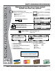
www.multiquip.com PARTS ORDERING PROCEDURES Ordering parts has never been easier! Choose from three easy options: Order via Internet (Dealers Only): Best Deal! Effective: January 1st, 2006 If you have an MQ Account, to obtain a Username and Password, E-mail us at: parts@multiquip. com. Order parts on-line using Multiquip’s SmartEquip website! ■ View Parts Diagrams ■ Order Parts ■ Print Specification Information To obtain an MQ Account, contact your District Sales Manager for more information.
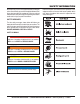
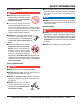
SAFETYALERT INFORMATION DCA-25USIXF/DCA-25USI2XF— SAFETY MESSAGE SYMBOLS Do not operate or service the equipment before reading the entire manual. Safety precautions should be followed at all times when operating this equipment. Failure to read and understand the safety messages and operating instructions could result in injury to yourself and others.
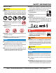
SAFETYALERT INFORMATION DCA-25USIXF/DCA-25USI2XF— SAFETY MESSAGE SYMBOLS GENERAL SAFETY CAUTION NEVER operate this equipment without proper protective clothing, shatterproof glasses, respiratory protection, hearing protection, steel-toed boots and other protective devices required by the job or city and state regulations. NEVER operate this equipment when not feeling well due to fatigue, illness or when under medication. NEVER operate this equipment under the influence of drugs or alcohol.
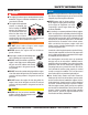
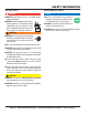
DCA-25USIXF/DCA-25USI2XF— RULES FOR SAFE OPERATION SAFETY INFORMATION ENGINE SAFETY DANGER The engine fuel exhaust gases contain poisonous carbon monoxide. This gas is colorless and odorless, and can cause death if inhaled. The engine of this equipment requires an adequate free flow of cooling air. NEVER operate this equipment in any enclosed or narrow area where free flow of the air is restricted.
SAFETY INFORMATION DCA-25USIXF/DCA-25USI2XF— RULES FOR SAFE OPERATION FUEL SAFETY DANGER DO NOT start the engine near spilled fuel or combustible fluids. Diesel fuel is extremely flammable and its vapors can cause an explosion if ignited. Make sure the hitch and coupling of the towing vehicle are rated equal to, or greater than the trailer “gross vehicle weight rating.” ALWAYS inspect the hitch and coupling for wear. NEVER tow a trailer with defective hitches, couplings, chains, etc.
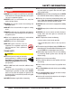
SAFETY INFORMATION DCA-25USIXF/DCA-25USI2XF— RULES FOR SAFE OPERATION ELECTRICAL SAFETY DANGER DO NOT touch output terminals during operation. Contact with output terminals during operation can cause electrocution, electrical shock or burn. The electrical voltage required to operate the generator can cause severe injury or even death through physical contact with live circuits.
SAFETY INFORMATION DCA-25USIXF/DCA-25USI2XF— RULES FOR SAFE OPERATION BATTERY SAFETY DANGER DO NOT drop the battery. There is a possibility that the battery will explode. DO NOT expose the battery to open flames, sparks, cigarettes, etc. The battery contains combustible gases and liquids. If these gases and liquids come into contact with a flame or spark, an explosion could occur. ENVIRONMENTAL SAFETY NOTICE Dispose of hazardous waste properly.
DCA-25USIXF/DCA-25USI2XF— RULES FORSPECIFICATIONS SAFE OPERATION Table 1. Generator Specifications Model DCA-25USIXF/DCA-25USI2XF Type Revolving field, self ventilated, open protected type synchronous generator Armature Connection Star with Neutral Zig Zag Phase 3 Single Standby Output 26.5 KVA (21.2 KW) 15.3 KW Prime Output 25 KVA (20 KW) 1 4 .4 K W Voltage 240V or 480V 2 4 0 /1 2 0 V Frequency 60 Hz S pe e d 1,800 rpm Power Factor 0.8 1 Aux.
DIMENSIONS DCA-25USIXF/DCA-25USI2XF— DIMENSIONS (TOP, SIDE AND FRONT) Figure 1. Dimensions TABLE 3. DIMENSIONS Reference Letter Dimension in. (mm.) Reference Letter Dimension in. (mm.) A 27.30 in. (695 mm.) F 86.20 in. (2,190 mm.) B 25.59 in. (650 mm.) G 56.90 in. (1,445 mm.) C 22.64 in. (575 mm.) H 31.10 in. (790 mm.) D 24.80 in. (630 mm.) E 20.90 in. (530 mm.) PAGE 12 — DCA25USIXF/DCA25USI2XF — OPERATION AND PARTS MANUAL — REV.
DECALS Figure 2. Generator Decals 1 DCA25USIXF/DCA25USI2XF — OPERATION AND PARTS MANUAL — REV.
DECALS Figure 3. Generator Decals (Continued) PAGE 14 — DCA25USIXF/DCA25USI2XF — OPERATION AND PARTS MANUAL — REV.
INSTALLATION Figure 4. Typical Generator Grounding Application 1 DCA25USIXF/DCA25USI2XF — OPERATION AND PARTS MANUAL — REV.
INSTALLATION Outdoor Installation Generator Grounding Install the generator in a area that is free of debris, bystanders, and overhead obstructions. Make sure the generator is on secure level ground so that it cannot slide or shift around. Also install the generator in a manner so that the exhaust will not be discharged in the direction of nearby homes. To guard against electrical shock and possible damage to the equipment, it is important to provide a good EARTH ground.
GENERAL INFORMATION FAMILIARIZATION Generator The MQ Power DCA-25USIXF/DCA-25USI2XF Ultra-Silent generators (Figure 5) are 56 kW generators that are designed as a high quality portable (requires a trailer for transport) power source for telecom sites, lighting facilities, power tools, submersible pumps and other industrial and construction machinery.
COMPONENTS Table 4. Generator Major Components ITEM NO. Figure 5. Major Components DESCRIPTION 1 Muffler Assembly 2 Engine Assembly 3 Generator Assembly 4 Output Terminal Assembly 5 Fuel Tank Assembly 6 Battery Assembly 7 Generator Control Panel Assembly 8 Engine Operating Panel Assembly PAGE 18 — DCA25USIXF/DCA25USI2XF — OPERATION AND PARTS MANUAL — REV.
GENERATOR CONTROL PANEL Figure 6. Generator Control Panel The definitions below describe the controls and functions of the "Generator Control Panel " (Figure 6). 1. Frequency Meter – Indicates the output frequency in hertz (Hz). Normally 60 Hz ±1 Hz. 2. Voltage Regulator Control – Allows ±15% manual adjustment of the generator’s output voltage. 3.
ENGINE OPERATING PANEL Figure 7. Engine Operating Panel The definitions below describe the controls and functions of the "Engine Operating Panel " (Figure 7). 1. 7. Panel Light - Normally used in dark places or at night. When activated, panel will luminate. When the generator is not in use, turn the panel light switch to the OFF 8. position. 9. Water Temperature Lamp - Indicates that the water temperature is outside of normal range and will shut down the engine.
OUTPUT TERMINAL PANEL Output Terminal Familiarization Output Terminal Panel The Output Terminal Panel (Figure 8) shown below is located The “Output Terminal Panel ” (Figure 6) is provided with the on the right-hand side (left from control panel) of the generator. following: Lift up on the cover to gain access to receptacles and terminal ■ Two (2) 120/240V output receptacles @ 50 amp lugs.
OUTPUT TERMINAL PANEL 120 VAC GFCI Receptacles There are two 120 VAC, 20 amp GFCI (Duplex Nema 5-20R) recepacles provided on the output terminal panel. These receptacles can be accessed in any voltage selector switch position. Each receptacle is protected by a 20 amp circuit breaker. These breakers are located directly above the GFCI receptacles. Remember the load output (current) of both GFCI receptacles is dependent on the load requirements of the U, V, and W output terminal lugs.
OUTPUT TERMINAL PANEL Connecting Loads Loads can be connected to the generator by the UVWO terminal lugs or the convienience receptacles. (See Figure 13). Make sure to read the operation manual before attempting to connect a load to the generator. To protect the UVWO output terminals from overload, a 3-pole, 60 amp, main circuit breaker is provided. Make sure to switch ALL circuit breakers to the "OFF" position prior to starting the engine.
LOAD APPLICATION Single Phase Load Always be sure to check the nameplate on the generator and equipment to insure the wattage, amperage, frequency, and voltage requirements are satisfactorily supplied by the generator for operating the equipment. Generally, the wattage listed on the nameplate of the equipment is its rated output. Equipment may require 130— 150% more wattage than the rating on the nameplate, as the wattage is influenced by the efficiency, power factor and starting system of the equipment.
GAUGE READING/TERMINAL PANEL CONNECTIONS Maximum Amps Voltage Selector Switch The voltage selector switch (Figure 15) is located above Table 8 shows the maximum amps the generator can prothe output terminal panel’s Hard Wire Hook-up Panel. It vide. DO NOT exceed the maximum amps as listed. has been provided for ease of voltage selection. Table 8. Generator Maximum Amps Figure 15.
GAUGE READING/TERMINAL PANEL CONNECTIONS The gauges and selector switches on the control panel DO NOT effect the generator output. They are provided to help observe how much power is being supplied at the Output terminals lugs. Before taking a reading from either gauge, set the Voltage Selector Switch (Figure 16) to the position which produces the required voltage (For example, for 3Ø 240V, choose the center 3Ø 240/139V position on the voltage selector switch.
OUTPUT TERMINAL PANEL CONNECTIONS UVWO Terminal Output Voltages Various output voltages can be obtained using the Output Terminal Lugs. The voltages at the terminals are dependent on the position of the Voltage Selector Switch and the adjustment of the Voltage Regulator Control Knob. Remember the voltage selector switch determines the range of the output voltage. The voltage regulator (VR) allows the user to increase or decrease the selected voltage. 3Ø 240/139 Output Terminal Lug Voltages 1.
OUTPUT TERMINAL PANEL CONNECTIONS 3Ø 480/277 Output Terminal Lug Voltages 1. Place the voltage selector switch in the 3Ø 480/277 position as shown in Figure 26. Figure 26. Voltage Selector Switch 480/277V Three-Phase Position 1Ø 240V/120V Output Terminal Lug Voltages 1. Place the voltage selector switch in the 1Ø 240/120 position as shown in Figure 28. Figure 28. Voltage Selector Switch 240/120V Single-Phase Position 2. Connect the load wires to the Output Terminal Lugs as shown in Figure 27. 2.
DCA-25USIXF/DCA-25USI2XF— SETUP SETUP Circuit Breakers Fuel Check To protect the generator from an overload, a 3-pole, 60 amp, main circuit breaker is provided to protect the UVW output terminals from overload. In addition two single-pole, 20 amp GFCI circuit breakers are provided to protect the GFCI receptacles from overload. Two 50 amp load circuit breakers have also been provided to protect the auxiliary receptacles from overload.
DCA-25USIXF/DCA-25USI2XF— SETUP SETUP Refueling Procedure: 3. WARNING - RESPIRATORY HAZARDS Open cabinet doors on the “right side” of the generator (from generator control panel position). Remove fuel cap and fill tank (Figure 33). Diesel fuel and its vapors are dangerous to your health and the surrounding environment. Avoid skin contact and/or inhaling fumes. 1. Level Tanks – Make sure fuel cells are level with the ground.
DCA-25USIXF/DCA-25USI2XF— SETUP SETUP Coolant (ISUZU Antifreeze/Summer Coolant/Water) ISUZU recommends ISUZU Antifreeze/Summer Coolant for use in thier engines, which can be purchased in concentrate (and mixed with 50% demineralized water) or pre-diluted. See the ISUZU Engine Owner's Manual for further details. Cleaning the Radiator The engine may overheat if the radiator fins become overloaded with dust or debris. Periodically clean the radiator fins with compressed air.
DCA-25USIXF/DCA-25USI2XF— SETUP SETUP Battery When connecting battery do the following: This unit is of negative ground DO NOT connect in reverse. 1. NEVER connect the battery cables to the battery Always maintain battery fluid level between the specified terminals when the ignition switch is in either the PreHeat, RUN, or START position. ALWAYS make sure marks. Battery life will be shortened, if the fluid level are not that the ignition switch is in the STOP position when properly maintained.
STARTUP Before Starting CAUTION - LETHAL EXHAUST HAZARD Start-up Procedure 1. Place the voltage selector switch in the desired voltage position (Figure 40). The engine's exhaust contains harmful emissions. ALWAYS have adequate ventilation when operating. Direct exhaust away from nearby personnel. WARNING - STARTING THE GENERATOR NEVER! manually start the engine with the main, GFCI or auxiliary circuit breakers in the ON (closed) position. 1. Place the main, G.F.C.I., and aux.
STARTUP 3. Turn the ignition key to the START position (Figure 43). 6. The generator's AC-voltmeter (Figure 45) displays the Once the engine starts, release the ignition key and output voltage in VOLTS. If the voltage is not within the allow it to return to the RUN position (Figure 41). specified frequency tolerance, use the voltage adjustment control knob (Figure 46) to increase or decrease the If the engine fails to start after 10 seconds, wait desired voltage.
STARTUP DCA-25USIXF/DCA-25USI2XF— GENERATOR START-UP PROCEDURE 8. The engine oil pressure gauge (Figure 48) will indicate 11. Turn the main, GFCI, and aux. circuit breakers to the the oil pressure of the engine. Under normal operating ON position (Figure 51). conditions the oil pressure is approximately 28~71 psi (193~490 kPa). Figure 48. Oil Pressure Gauge Figure 51. Main, AUX. and GFCI Circuit Breakers (ON) 9. The coolant temperature gauge (Figure 49) will indicate the coolant temperature.
DCA-25USIXF/DCA-25USI2XF— GENERATOR SHUT-DOWN SHUTDOWN PROCEDURE Normal Shut-down Procedure To shutdown the generator, use the following procedure: 1. Switch the MAIN, AUX and GFCI circuit breakers (Figure 53) to the OFF position (no load). Emergency Shut-down Procedure 1. To shut-down the engine in the event of an emergency, switch the MAIN, GFCI and LOAD (Figure 53) circuit breakers to OFF position. 2. Turn the ignition switch key to the STOP position (Figure 54).
DCA-25USIXF/DCA-25USI2XF— MAINTENANCE MAINTENANCE 10 Hrs DAILY TABLE 14.
MAINTENANCE DCA-25USIXF/DCA-25USI2XF— MAINTENANCE Air Removal If air enters the fuel injection system of a diesel engine, starting becomes impossible. After running out of fuel, or after disassembling the fuel system, bleed the system according to the following procedure. To restart after running out of fuel, turn the switch to the ON position for 15-30 seconds. Try again, if needed. This unit is equipped with an automatic air bleeding system.
TRAILER MAINTENANCE Brakes Trailer brakes should be inspected the first 200 miles of operation. This will allow the brake shoes and drums to seat properly. After the first 200 mile interval, inspect the brakes every 3,000 miles. If driving over rough terrain, inspect the brakes more frequently. Figure 55 displays the major hydraulic surge brake components that will require inspection and maintenance.
TRAILER MAINTENANCE Tires/Wheels/Lug Nuts Tires and wheels are a very important and critical components of the trailer. When specifying or replacing the trailer wheels it is important the wheels, tires, and axle are properly matched. CAUTION - EYESIGHT HAZARD Suspension The leaf suspension springs and associated components (Figure 56) should be visually inspected every 6,000 miles for signs of excessive wear, elongation of bolt holes, and loosening of fasteners.
TRAILER MAINTENANCE DCA-25USIXF/DCA-25USI2XF— TRAILER MAINTENANCE Lug Nut Torque Requirements It is extremely important to apply and maintain proper wheel mounting torque on the trailer. Be sure to use only the fasteners matched to the cone angle of the wheel. Proper procedure for attachment of the wheels is as follows: 1. Start all wheel lug nuts by hand. 2. Torque all lug nuts in sequence (see Figure 57). DO NOT torque the wheel lug nuts all the way down.
TRAILER WIRING DCA-25USIXF/DCA-25USI2XF— TRAILER WIRINGDIAGRAM DIAGRAM Figure 58. Trailer/Towing Vehicle Wiring Diagram PAGE 42 — DCA25USIXF/DCA25USI2XF — OPERATION AND PARTS MANUAL — REV.
ENGINE WIRING DIAGRAM Figure 59A. Engine Wiring Diagram 1 DCA25USIXF/DCA25USI2XF — OPERATION AND PARTS MANUAL — REV.
ENGINE WIRING DIAGRAM Figure 59B. Engine Wiring Diagram(Continued) PAGE 44 — DCA25USIXF/DCA25USI2XF — OPERATION AND PARTS MANUAL — REV.
GENERATOR WIRING DIAGRAM Figure 60. Generator Wiring Diagram 1 DCA25USIXF/DCA25USI2XF — OPERATION AND PARTS MANUAL — REV.
TROUBLESHOOTING Practically all breakdowns can be prevented by proper handling and maintenance inspections, but in the event of a breakdown, use Table 19 shown below for diagnosis of the engine. If the problem cannot be remedied, consult our company's business office or service plant. TABLE 19. ENGINE TROUBLESHOOTING SYMPTOM Engine does not star t. POSSIBLE PROBLEM SOLUTION No fuel? Replenish fuel. Air in the fuel system? Bleed system. Water in the fuel system? Remove water from fuel tank.
TROUBLESHOOTING TABLE 19. ENGINE TROUBLESHOOTING (CONTINUED) SYMPTOM Engine revolution is not smooth. Either white or blue exhaust gas is observed. Either black or dark gray exhaust gas is observed. Deficient output. POSSIBLE PROBLEM SOLUTION Fuel filter clogged or dir ty? Clean or change. Air cleaner clogged? Clean or change. Fuel leak due to loose injection pipe retaining nut? Tighten nut. Injection pump malfunctioning? Repair or replace. Incorrect nozzle opening pressure? Adjust.
TROUBLESHOOTING Practically all breakdowns can be prevented by proper handling and maintenance inspections, but in the event of a breakdown, use Table 20 shown below for diagnosis of the Generator. If the problem cannot be remedied, consult our company's business office or service plant. TABLE 20. GENERATOR TROUBLESHOOTING SYMPTOM No Voltage Output Low Voltage Output High Voltage Output Circuit Breaker Tripped POSSIBLE PROBLEM SOLUTION AC Voltmeter defective? Check output voltage using a voltmeter.
NOTES 1 DCA25USIXF/DCA25USI2XF — OPERATION AND PARTS MANUAL — REV.
EXPLANATION OF CODE IN REMARKS COLUMN The following section explains the different symbols and remarks used in the Parts section of this manual. Use the help numbers found on the back page of the manual if there are any questions. NOTICE The contents and part numbers listed in the parts section are subject to change without notice. Multiquip does not guarantee the availability of the parts listed. SAMPLE PARTS LIST NO. 1 2% 2% 3 4 PART NO. PART NAME QTY. REMARKS 12345 BOLT......................1 .....
SUGGESTED SPARE PARTS DCA-25USIXF/DCA-25USI2XF (Big Tank) W/ISUZU AA-4LE2/BV-4LE2 DIESEL ENGINES 1 TO 3 UNITS Qty. P/N Description Remarks 3 ......... 8944567411 .............. OIL FILTER, DCA-25USI 3 ......... 8944567412 .............. ELEMENT OIL FILTER, DCA-25USI2 3 ......... 0602046611 .............. AIR ELEMENT 3 ......... 8943692993 .............. CARTRIDGE, FUEL FILTER 1 ......... 0602122272 .............. UNIT, OIL PRESSURE 1 ......... 0602123266 .............. UNIT WATER TEMPERATURE, DCA-25USI 1 .
GENERATOR ASSY. GENERATOR ASSY. PAGE 52 — DCA25USIXF/DCA25USI2XF — OPERATION AND PARTS MANUAL — REV.
GENERATOR ASSY. GENERATOR ASSY. NO. PART NO.
DCA25USIXF — CONTROL BOX ASSY. CONTROL BOX ASSY. (DCAUSIXF ONLY) PAGE 54 — DCA25USIXF/DCA25USI2XF — OPERATION AND PARTS MANUAL — REV.
DCA25USIXF — CONTROL BOX ASSY. CONTROL BOX ASSY. (DCAUSIXF ONLY) NO. PART NO. PART NAME QTY.
DCA25USIXF — CONTROL BOX ASSY. CONTROL BOX ASSY. (DCAUSIXF ONLY) PAGE 56 — DCA25USIXF/DCA25USI2XF — OPERATION AND PARTS MANUAL — REV.
DCA25USIXF — CONTROL BOX ASSY. CONTROL BOX ASSY. (DCAUSIXF ONLY) NO. PART NO. PART NAME QTY. REMARKS 28 0016906016 HEX, HEAD BOLT 9 28A 0040506000 TOOTHED WASHER 1 29 M1225000323 CONTROL PANEL ...............................................1 ............. S/N 8100001~8100586 29 M1225000333 CONTROL PANEL ...............................................1 .............
DCA25USI2XF — CONTROL BOX ASSY. CONTROL BOX ASSY. (DCAUSI2XF ONLY) PAGE 58 — DCA25USIXF/DCA25USI2XF — OPERATION AND PARTS MANUAL — REV.
DCA25USI2XF — CONTROL BOX ASSY. CONTROL BOX ASSY. (DCAUSIXF ONLY) NO. PART NO. PART NAME QTY.
DCA25USI2XF — CONTROL BOX ASSY. CONTROL BOX ASSY. (DCAUSI2XF ONLY) PAGE 60 — DCA25USIXF/DCA25USI2XF — OPERATION AND PARTS MANUAL — REV.
DCA25USI2XF — CONTROL BOX ASSY. CONTROL BOX ASSY. (DCAUSI2XF ONLY) NO. PART NO. PART NAME QTY. REMARKS 37 M1223000603 CONTROL PANEL ...............................................1 .............
DCA25USIXF — ENGINE AND RADIATOR ASSY. ENGINE AND RADIATOR ASSY. (DCAUSIXF ONLY) PAGE 62 — DCA25USIXF/DCA25USI2XF — OPERATION AND PARTS MANUAL — REV.
DCA25USIXF — ENGINE AND RADIATOR ASSY. ENGINE AND RADIATOR ASSY. (DCAUSIXF ONLY) NO. PART NO. PART NAME QTY. REMARKS 1 B1925200254 ENGINE, ISUZU AA-4LE2 1 1-1 8944567411 CARTRIDGE, OIL FILTER ............................. 1 ...........
DCA25USIXF — ENGINE AND RADIATOR ASSY. ENGINE AND RADIATOR ASSY. (DCAUSIXF ONLY) PAGE 64 — DCA25USIXF/DCA25USI2XF — OPERATION AND PARTS MANUAL — REV.
DCA25USIXF — ENGINE AND RADIATOR ASSY. ENGINE AND RADIATOR ASSY. (DCAUSIXF ONLY) NO. PART NO. PART NAME QTY.
DCA25USI2XF — ENGINE AND RADIATOR ASSY. ENGINE AND RADIATOR ASSY. (DCAUSI2XF ONLY) PAGE 66 — DCA25USIXF/DCA25USI2XF — OPERATION AND PARTS MANUAL — REV.
DCA25USI2XF — ENGINE AND RADIATOR ASSY. ENGINE AND RADIATOR ASSY. (DCAUSI2XF ONLY) NO. PART NO. PART NAME QTY. REMARKS 1 M1923200124 ENGINE, ISUZU BV-4LE2 1 1-1 8944567412 CARTRIDGE, OIL FILTER ............................. 1 ...........
DCA25USI2XF — ENGINE AND RADIATOR ASSY. ENGINE AND RADIATOR ASSY. (DCAUSI2XF ONLY) PAGE 68 — DCA25USIXF/DCA25USI2XF — OPERATION AND PARTS MANUAL — REV.
DCA25USI2XF — ENGINE AND RADIATOR ASSY. ENGINE AND RADIATOR ASSY. (DCAUSI2XF ONLY) NO. PART NO. PART NAME QTY.
OUTPUT TERMINAL ASSY. OUTPUT TERMINAL ASSY. ADD THE FOLLOWING DIGITS AFTER THE PART NUMBER WHEN ORDERING ANY PAINTED PANEL TO INDICATE COLOR OF UNIT: 1-ORANGE 2-WHITE 3-SPECTRUM GREY 4-SUNBELT GREEN 5-BLACK 6-CATERPILLAR YELLOW 7-CATO GOLD 8-RED THE SERIAL NUMBER MAY BE REQUIRED. PAGE 70 — DCA25USIXF/DCA25USI2XF — OPERATION AND PARTS MANUAL — REV.
OUTPUT TERMINAL ASSY. OUTPUT TERMINAL ASSY. NO. PART NO.
BATTERY ASSY. BATTERY ASSY. PAGE 72 — DCA25USIXF/DCA25USI2XF — OPERATION AND PARTS MANUAL — REV.
BATTERY ASSY. BATTERY ASSY. NO. PART NO. 1 0602220185 2 M9310500014 3 M9103000304 4 0602220920 5 0040006000 6 M1348400204 7 M1348400314 8 0016910020 8A 0040510000 PART NAME BATTERY BATTERY SHEET BATTERY BAND BATTERY BOLT SET WASHER, LOCK BATTERY CABLE BATTERY CABLE HEX, HEAD BOLT TOOTHED WASHER QTY. 1 1 1 2 2 1 1 1 1 REMARKS 1 DCA25USIXF/DCA25USI2XF — OPERATION AND PARTS MANUAL — REV.
DCA25USIXF — MUFFLER DCA-25USIXF— MUFFLER ASSY. ASSY. MUFFLER ASSY. (DCA-25USIXF ONLY) PAGE 74 — DCA25USIXF/DCA25USI2XF — OPERATION AND PARTS MANUAL — REV.
DCA25USIXF —— MUFFLER DCA-25USIXF MUFFLER ASSY. ASSY. MUFFLER ASSY. (DCA-25USIXF ONLY) NO. PART NO. PART NAME QTY. REMARKS 1 M1332000002 MUFFLER ....................................................... 1 ........... S/N 810000 ~8101465 1 M1332000012 MUFFLER ....................................................... 1 ........... S/N 8101466 AND ABOVE 2 0016908020 HEX, HEAD BOLT 7 3 M1335000103 EXHAUST PIPE ............................................. 1 ...........
DCA25USI2XF — MUFFLER ASSY. MUFFLER ASSY. (DCA-25USI2XF ONLY) PAGE 76 — DCA25USIXF/DCA25USI2XF — OPERATION AND PARTS MANUAL — REV.
DCA25USI2XF — MUFFLER ASSY. MUFFLER ASSY. (DCA-25USI2XF ONLY) NO. PART NO. PART NAME QTY. REMARKS 1 M1332000512 MUFFLER 1 2 M1333200304 GASKET 1 3 0016908035 HEX, HEAD BOLT 6 4 M1333300204 STAY 1 5 0016908020 HEX, HEAD BOLT 6 6 M1333003013 EXHAUST PIPE 1 6-1 M1490003604 HEAT INSULATOR1 7 8970420280 GASKET ........................................................ 1 ...........
FUEL TANK DCA-25USIXF/DCA-25USI2XF— FUEL TANK ASSY. ASSY. FUEL TANK ASSY. PAGE 78 — DCA25USIXF/DCA25USI2XF — OPERATION AND PARTS MANUAL — REV.
DCA-25USIXF/DCA-25USI2XF— FUEL FUEL TANK TANK ASSY. ASSY. FUEL TANK ASSY. NO. PART NO. 1 M1363001302 2 0605505072 3 0605501098 4 0605516090 5 0027104016 6 M1363300314 7 0016908035 8 0602022791 9 0191301200 10 0605515109 11 8943672922 11A 8943692993 12 M1368700004 13 0016908020 14 8970398340 14A 8944370220 15 0016906025 16 M1363400404 17 0603306863 18 0602022971 19 0191200330 20 0191200200 21 0191201300 22 0191200800 23 0605515198 24 0603306797 25 0222100550 PART NAME QTY.
DCA25USIXF — ECLOSURE ASSY. ENCLOSURE ASSY. (DCA25USIXF ONLY) PAGE 80 — DCA25USIXF/DCA25USI2XF — OPERATION AND PARTS MANUAL — REV.
DCA25USIXF — ECLOSURE ASSY. ENCLOSURE ASSY. (DCA25USIXF ONLY) NO. PART NO. PART NAME QTY.
DCA-25USIXF— ENCLOSURE ASSY. (CONTINUED) DCA25USIXF — ECLOSURE ASSY. ENCLOSURE ASSY. (DCA25USIXF ONLY) PAGE 82 — DCA25USIXF/DCA25USI2XF — OPERATION AND PARTS MANUAL — REV.
DCA25USIXF — ECLOSURE ASSY. DCA-25USIXF— ENCLOSURE ASSY. (CONTINUED) ENCLOSURE ASSY. (DCA25USIXF ONLY) NO. PART NO. PART NAME 27 M1445300103 REAR COVER 27A M1495300504 ACOUSTIC SHEET 27B M1495300604 ACOUSTIC SHEET 28 M1445400103 DUCT 28A M1495300604 ACOUSTIC SHEET 29 0207006000 HEX, NUT 30 0019208020 HEX, HEAD BOLT 31 M1445200303 REAR DOOR 32 M1445600204 WINDOW PLATE 33 0207306000 HEX, NUT 33A 0041206000 WASHER, FLAT 34 M9113000002 DOOR HANDLE ASSY.
DCA25USIXF — ECLOSURE ASSY. DCA-25USIXF— ENCLOSURE ASSY. (CONTINUED) ENCLOSURE ASSY. (DCA25USIXF ONLY) PAGE 84 — DCA25USIXF/DCA25USI2XF — OPERATION AND PARTS MANUAL — REV.
DCA25USIXF — ECLOSURE ASSY. DCA-25USIXF— ENCLOSURE ASSY. (CONTINUED) ENCLOSURE ASSY. (DCA25USIXF ONLY) NO. PART NO. PART NAME QTY. REMARKS 51 M9113000002 DOOR HANDLE ASSY.
DCA25USI2XF — ECLOSURE ASSY. ENCLOSURE ASSY. (DCA25USI2XF ONLY) PAGE 86 — DCA25USIXF/DCA25USI2XF — OPERATION AND PARTS MANUAL — REV.
DCA25USI2XF — ECLOSURE ASSY. ENCLOSURE ASSY. (DCA25USIXF ONLY) NO. PART NO.
DCA25USI2XF — ASSY. ECLOSURE ASSY. DCA-25USI2XF— ENCLOSURE (CONTINUED) ENCLOSURE ASSY. (DCA25USI2XF ONLY) PAGE 88 — DCA25USIXF/DCA25USI2XF — OPERATION AND PARTS MANUAL — REV.
DCA25USI2XF — ASSY. ECLOSURE ASSY. DCA-25USI2XF— ENCLOSURE (CONTINUED) ENCLOSURE ASSY. (DCA25USI2XF ONLY) NO. PART NO. PART NAME 31 0016906016 HEX, HEAD BOLT 32 0207006000 HEX, NUT 33 0019208020 HEX, HEAD BOLT 34 M1443302203 REAR COVER 34A M1493305104 ACOUSTIC SHEET 35 M1443400103 DUCT 35A M1493305204 ACOUSTIC SHEET 36 0207006000 HEX, NUT 37 0019208020 HEX, HEAD BOLT 38 M1445200303 REAR DOOR 39 M1445600204 WINDOW PLATE 40 0207306000 HEX, NUT 40A 0041206000 WASHER, FLAT 41 M9113000002 DOOR HANDLE ASSY.
DCA25USI2XF — ASSY. ECLOSURE ASSY. DCA-25USI2XF— ENCLOSURE (CONTINUED) ENCLOSURE ASSY. (DCA25USI2XF ONLY) PAGE 90 — DCA25USIXF/DCA25USI2XF — OPERATION AND PARTS MANUAL — REV.
DCA25USI2XF — ASSY. ECLOSURE ASSY. DCA-25USI2XF— ENCLOSURE (CONTINUED) ENCLOSURE ASSY. (DCA25USI2XF ONLY) NO. PART NO. PART NAME 58 M9113000002 DOOR HANDLE ASSY.
RUBBER DCA-25USIXF/DCA-25USI2XF— RUBBERSEALS SEALS ASSY. ASSY. RUBBER SEALS ASSY. PAGE 92 — DCA25USIXF/DCA25USI2XF — OPERATION AND PARTS MANUAL — REV.
RUBBER DCA-25USIXF/DCA-25USI2XF— RUBBERSEALS SEALS ASSY. ASSY. RUBBER SEALS ASSY. NO. PART NO.
NAMEPLATE AND DECALS ASSY. NAME PLATE ASSY. PAGE 94 — DCA25USIXF/DCA25USI2XF — OPERATION AND PARTS MANUAL — REV.
NAMEPLATE AND DECALS ASSY. NAME PLATE ASSY. NO. PART NO.
TERMS AND CONDITIONS OF SALE — PARTS PAYMENT TERMS 5. Parts must be in new and resalable condition, in the original Multiquip package (if any), and with Multiquip part numbers clearly marked. 6. The following items are not returnable: Terms of payment for parts are net 10 days. FREIGHT POLICY All parts orders will be shipped collect or prepaid with the charges added to the invoice. All shipments are F.O.B. point of origin.
NOTENOTES PAGE 1 DCA25USIXF/DCA25USI2XF — OPERATION AND PARTS MANUAL — REV.
PARTS AND OPERATION MANUAL OPERATION AND PARTS MANUAL HERE’S HOW TO GET HELP PLEASE HAVE THE MODEL AND SERIAL NUMBER ON-HAND WHEN CALLING UNITED STATES Multiquip Corporate Office 18910 Wilmington Ave. Carson, CA 90746 Contact: mq@multiquip.com MQ Parts Department Tel.