PARTS AND OPERATION MANUAL OPERATION AND PARTS MANUAL ® MODEL DCA125USJ 60 Hz GENERATOR (JOHN DEERE 6068TF 275 DIESEL ENGINE) PARTS LIST NO. M3870400004 Revision #2 (01/27/11) To find the latest revision of this publication, visit our website at: www.multiquip.com THIS MANUAL MUST ACCOMPANY THE EQUIPMENT AT ALL TIMES.
PAGE 2 — DCA-125USJ — OPERATION AND PARTS MANUAL — REV.
NOTE PAGE 1 DCA-125USJ — OPERATION AND PARTS MANUAL — REV.
TABLE OF CONTENTS MQ POWER DCA12USJ AC GENERA TOR GENERATOR California Proposition 65 Warning ..................................... 2 Here's How To Get Help .................................................... 3 Table Of Contents ............................................................. 4 Parts Ordering Procedures ............................................... 5 Specifications ................................................................... 6 Dimensions (Top, Side, Front) ...........................
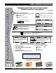
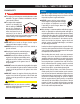
www.multiquip.com PARTS ORDERING PROCEDURES Ordering parts has never been easier! Choose from three easy options: Order via Internet (Dealers Only): Best Deal! Effective: January 1st, 2006 If you have an MQ Account, to obtain a Username and Password, E-mail us at: parts@multiquip. com. Order parts on-line using Multiquip’s SmartEquip website! ■ View Parts Diagrams ■ Order Parts ■ Print Specification Information To obtain an MQ Account, contact your District Sales Manager for more information.
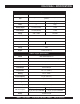
DCA-125USJ — SPECIFICATIONS Table 1. Generator Specifications Model DCA125USJ Type Revolving field, self ventilated, open protected type synchronous generator Armature Connection Star with Neutral Zig Zag Phase 3 Single Standby Output 137 KVA (110 KW) 79 KW Prime Output 125 KVA (100 KW) 72 KW Voltage 240 V or 480V 240/120V Frequency 60 Hz S pe e d 1800 r pm Power Factor 0.8 1 Aux. AC Power Single Phase, 60 Hz Voltage 120 V Output 4.8 KW (2.4 KW x 2) Table 2.
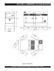
DCA-125USJ — DIMENSIONS (TOP, SIDE AND FRONT) Figure 1. Dimensions DCA-125USJ — OPERATION AND PARTS MANUAL — REV.
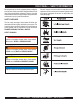
DCA-125USJ — SAFETY INFORMATION Do not operate or service the equipment before reading the entire manual. Safety precautions should be followed at all times when operating this equipment. Failure to read and understand the safety messages and operating instructions could result in injury to yourself and others. Potential hazards associated with the operation of this equipment will be referenced with hazard symbols which may appear throughout this manual in conjunction with safety messages.
DCA-125USJ — SAFETY INFORMATION GENERAL SAFETY CAUTION NEVER operate this equipment without proper protective clothing, shatterproof glasses, respiratory protection, hearing protection, steel-toed boots and other protective devices required by the job or city and state regulations. NEVER operate this equipment when not feeling well due to fatigue, illness or when under medication. NEVER operate this equipment under the influence of drugs or alcohol.
DCA-125USJ — SAFETY INFORMATION ENGINE SAFETY NOTICE DANGER The engine fuel exhaust gases contain poisonous carbon monoxide. This gas is colorless and odorless, and can cause death if inhaled. The engine of this equipment requires an adequate free flow of cooling air. NEVER operate this equipment in any enclosed or narrow area where free flow of the air is restricted. If the air flow is restricted it will cause injury to people and property and serious damage to the equipment or engine.
DCA-125USJ — SAFETY INFORMATION Make sure the hitch and coupling of the towing vehicle are rated equal to, or greater than the trailer “gross vehicle weight rating.” FUEL SAFETY DANGER DO NOT start the engine near spilled fuel or combustible fluids. Diesel fuel is extremely flammable and its vapors can cause an explosion if ignited. ALWAYS inspect the hitch and coupling for wear. NEVER tow a trailer with defective hitches, couplings, chains, etc.
DCA-125USJ — SAFETY INFORMATION ELECTRICAL SAFETY DANGER DO NOT touch output terminals during operation. Contact with output terminals during operation can cause electrocution, electrical shock or burn. The electrical voltage required to operate the generator can cause severe injury or even death through physical contact with live circuits. Turn generator and all circuit breakers OFF before performing maintenance on the generator or making contact with output terminals.
DCA-125USJ — SAFETY INFORMATION BATTERY SAFETY DANGER ENVIRONMENTAL SAFETY NOTICE DO NOT drop the battery. There is a possibility that the battery will explode. DO NOT expose the battery to open flames, sparks, cigarettes, etc. The battery contains combustible gases and liquids. If these gases and liquids come into contact with a flame or spark, an explosion could occur. Dispose of hazardous waste properly. Examples of potentially hazardous waste are used motor oil, fuel and fuel filters.
DCA-125USJ — GENERATOR DECALS The DCA-125USJ generator is equipped with a number of safety decals (Figures 2 and 3). These decals are provided for operator safety and maintenance information. The illustration below and on the preceding page show the decals as they appear on the machine. Should any of these decals become unreadable, replacements can be obtained from your dealer. Figure 2. Generator Decals PAGE 14 — DCA-125USJ — OPERATION AND PARTS MANUAL — REV.
DCA-125USJ — GENERATOR DECALS Figure 3. Generator Decals (Cont.) DCA-125USJ — OPERATION AND PARTS MANUAL — REV.
DCA-125USJ — INSTALLATION Figure 4. Typical Generator Grounding Application PAGE 16 — DCA-125USJ — OPERATION AND PARTS MANUAL — REV.
DCA-125USJ — INSTALLATION Outdoor Installation Install the generator in a area that is free of debris, bystanders, and overhead obstructions. Make sure the generator is on secure level ground so that it cannot slide or shift around. Also install the generator in a manner so that the exhaust will not be discharged in the direction of nearby homes. The installation site must be relatively free from moisture and dust. All electrical equipment should be protected from excessive moisture.
DCA-125USJ — GENERAL INFORMATION DCA-125USJ Series Familiarization Generator The MQ Power Model DCA-125USJ is a 100 kW generator (Figure 5) that is designed as a high quality portable (requires a trailer for transport) power source for telecom sites, lighting facilities, power tools, submersible pumps and other industrial and construction machinery.
DCA-125USJ — MAJOR COMPONENTS Table 3. Generator Major Components ITEM NO. DESCRIPTION 1 Muffler Assembly 2 Engine Assembly 3 Enclosure Assembly 4 Generator Assembly 5 Output Terminal Assembly 6 Fuel Tank Assembly 7 Battery Assembly 8 Generator Control Panel Assembly 9 Engine Operating Panel Assembly Figure 5. Major Components 1 DCA-125USJ — OPERATION AND PARTS MANUAL — REV.
NOTE PAGE PAGE 20 — DCA-125USJ — OPERATION AND PARTS MANUAL — REV.
DCA-125USJ — GENERATOR CONTROL PANEL Figure 6. Generator Control Panel The definitions below describe the controls and functions of Located behind the generator control panel is the Generator Control Box. This box contains some of the necessary the DCA-125USJ Generator Control Panel (Figure 6). 1. Main Circuit Breaker – This three-pole, 300A main electronic components required to make the generator breaker is provided to protect the the U,V, and W Output function. 2. 3. 4. 5. 6. 7.
DCA-125USJ — ENGINE OPERATING PANEL Figure 7. Engine Operating Panel PAGE 22 — DCA-125USJ — OPERATION AND PARTS MANUAL — REV.
DCA-125USJ — ENGINE OPERATING PANEL The definitions below describe the controls and functions of During cranking cycle , The MPEC will attempt to crank the the DCA-125USJ Engine Operating Panel (Figure 7). engine for 10 seconds before disengaging. If the engine does 1. Panel Light – Normally used in dark areas or at night not engage (start) by the third attempt, the engine will be time. When activated, panel lights will illuminate.
DCA-125USJ — OUTPUT TERMINAL PANEL FAMILIARIZATION Output Terminal Panel The Output Terminal Panel (Figure 8) shown below is located on the right-hand side (left from control panel) of the generator. Lift up on the cover to gain access to receptacles and terminal lugs. NOTE Terminal legs “O” and “Ground” are considered bonded grounds.
DCA-125USJ — OUTPUT TERMINAL PANEL FAMILIARIZATION 120 VAC GFCI Receptacles There are two 120 VAC, 20 amp GFCI (Duplex Nema 5-20R) recepacles provided on the output terminal panel. These receptacles can be accessed in any voltage selector switch position. Each receptacle is protected by a 20 amp circuit breaker. These breakers are located directly above the GFCI receptacles. Remember the load output (current) of both GFCI receptacles is dependent on the load requirements of the UVWO terminals.
DCA-125USJ — OUTPUT TERMINAL PANEL FAMILIARIZATION Connecting Loads Loads can be connected to the generator by the Ouput Terminal Lugs or the convienience receptacles. (See Figure 13). Make sure to read the operation manual before attempting to connect a load to the generator. To protect the output terminals from overload, a 3-pole, 300A main circuit breaker is provided. Make sure to switch ALL circuit breakers to the OFF position prior to starting the engine.
DCA-125USJ — LOAD APPLICATION Single Phase Load Three Phase Load Always be sure to check the nameplate on the generator and equipment to insure the wattage, amperage, frequency, and voltage requirements are satisfactorily supplied by the generator for operating the equipment. When calculating the power requirements for 3-phase power use the following equation: Generally, the wattage listed on the nameplate of the equipment is its rated output.
DCA-125USJ — GENERATOR OUTPUTS Voltage Selector Switch Generator Amperage The voltage selector switch (Figure 16) is located above Table 7 describes the generator’s current output capability the output terminal panel’s Hard Wire Hook-up Panel. It for both 1Ø-phase and 3Ø phase applications. has been provided for ease of voltage selection. Table 7.
DCA-125USJ — GAUGE READING How to Read the Output Terminal Gauges. The gauges and selector switches on the control panel DO NOT effect the generator output. They are provided to help observe how much power is being supplied at the Output terminals lugs. Before taking a reading off either gauge, set the Voltage Selector Switch (Figure 17) to the position which produces the required voltage (For example, for 3Ø 240V, choose the center 3Ø 240/ 139V position on the voltage selector switch.
DCA-125USJ — OUTPUT TERMINAL PANEL CONNECTIONS UVWO Terminal Output Voltages Various output voltages can be obtained using the Output Terminal Lugs.. The voltages at the terminals are dependent on the position of the Voltage Selector Switch and the adjustment of the Voltage Regulator Control Knob. Remember the voltage selector switch determines the range of the output voltage. The voltage regulator (VR) allows the user to increase or decrease the selected voltage.
DCA-125USJ — OUTPUT TERMINAL PANEL CONNECTIONS 3Ø 480/277 Output Terminal Lug Voltages 1Ø 240V/120V Output Terminal Lug Voltages 1. Place the voltage selector switch in the 3Ø 480/277 1. Place the voltage selector switch in the 1Ø 240/120 position as shown in Figure 27. position as shown in Figure 29. Figure 27. Voltage Selector Switch 480/277V Three-Phase Position Figure 29. Voltage Selector Switch 240/120V Single-Phase Position 2. Connect the load wires to the Output Terminal Lugs as 2.
DCA-125USJ — PRE-SETUP Fuel Check Circuit Breakers To protect the generator from an overload, a 3-pole, 110 amp, main circuit breaker is provided to protect the U,V, and W Output Terminals from overload. In addition two single-pole, 20 amp GFCI circuit breakers are provided to protect the GFCI receptacles from overload. Three 50 amp load circuit breakers have also been provided to protect the auxiliary receptacles from overload.
DCA-125USJ — PRE-SETUP Refueling Procedure: 2. WARNING - RESPIRATORY HAZARDS Open cabinet doors on the “right side” of the generator (from generator control panel position). Remove fuel cap and fill tank (Figure 34). Diesel fuel and its vapors are dangerous to your health and the surrounding environment. Avoid skin contact and/or inhaling fumes. 1. Level Tanks – Make sure fuel cells are level with the ground.
DCA-125USJ — PRE-SETUP Coolant (John Deere Antifreeze/Summer Coolant/Water) John Deere recommends John Deere Antifreeze/Summer Coolant for use in thier engines, which can be purchased in concentrate (and mixed with 50% demineralized water) or pre-diluted. See the John Deere Engine Owner's Manual for further details. NOTE When the antifreeze is mixed with water, the antifreeze mixing ratio must be less than 50%.
DCA-125USJ — PRE-SETUP Battery When connecting battery do the following: This unit is of negative ground DO NOT connect in reverse. 1. NEVER connect the battery cables to the battery Always maintain battery fluid level between the specified terminals when the MPEC Control Switch is in either marks. Battery life will be shortened, if the fluid level are not the MANUAL position. ALWAYS make sure that the MPEC Control Switch is in the OFF/RESET position properly maintained.
DCA-125USJ — GENERATOR START-UP PROCEDURE (MANUAL) Before Starting CAUTION - LETHAL EXHAUST HAZARD The engine's exhaust contains harmful emissions. ALWAYS have adequate ventilation when operating. Direct exhaust away from nearby personnel. 5. Place the voltage selector switch in the desired voltage position (Figure 41). Figure 41. Voltage Selector Switch WARNING - STARTING THE GENERATOR NEVER! manually start the engine with the main, GFCI or auxiliary circuit breakers in the ON (closed) position.
DCA-125USJ — GENERATOR START-UP PROCEDURE (MANUAL) 9. The generator's frequency meter (Figure 45) should be displaying the 60 cycle output frequency in HERTZ. 13. The coolant temperature gauge (Figure 50) will indicate the coolant temperature. Under normal operating conditions the coolant temperature should be between 165 and 215 degrees Fahrenheit (Green Zone). Figure 45. Frequency Meter (Hz) 10. The generator's AC-voltmeter (Figure 46) will display the generator’s output in VOLTS.
DCA-125USJ — GENERATOR START-UP PROCEDURE (AUTO MODE) 16. Observe the generator's ammeter (Figure 53) and verify it reads the anticipated amount of current with respect to the load. The ammeter will only display a current reading if a load is in use. WARNING - AUTO MODE MAINTENANCE When running the generator in the AUTO mode, remember the generator can start up at any time without warning. NEVER attempt to perform any maintenance when the generator is in the auto mode.
DCA-125USJ — GENERATOR SHUT-DOWN PROCEDURE WARNING - SHUTTING DOWN THE GENERATOR NEVER stop the engine suddenly except in an emergency. Normal Shutdown Procedure To shutdown the generator use the following procedure: Emergency Shutdown Procedure 1. To shut-down the engine in the event of an emergency, switch the MAIN, GFCI and LOAD (Figure 38) circuit breakers to OFF position. 2. Place the MPEC Control Switch switch (Figure 55) to the OFF/RESET position. 1.
DCA-125USJ — MAINTENANCE 10 Hrs DAILY TABLE 13.
DCA-125USJ — MAINTENANCE Air Removal Flushing Out Radiator and Replacing Coolant If air enters the fuel injection system of a diesel engine, starting becomes impossible. After running out of fuel, or Open both cocks located at the crankcase side and at the lower part of the radiator and drain coolant. Open the after disassembling the fuel system, bleed the system radiator cap while draining. Remove the overflow tank according to the following procedure. See the John Deere and drain.
DCA-125USJ — MAINTENANCE Jacket Water Heater and Internal Battery Charger 120 VAC Input Receptacles (OPTIONAL) This generator can be optionally equipped with two 120 VAC, 20 amp input receptacles located on the output terminal panel. The purpose of these receptacles is to provide power via commercial power to the jacket water heater and internal battery charger. These receptacles will ONLY function when commercial power has been supplied to them (Figure 56).
DCA-125USJ — TRAILER BRAKES MAINTENANCE Brakes Trailer brakes should be inspected the first 200 miles of operation. This will allow the brake shoes and drums to seat properly. After the first 200 mile interval, inspect the brakes every 3,000 miles. If driving over rough terrain, inspect the brakes more frequently. Figure 60 displays the major hydraulic surge brake components that will require inspection and maintenance.
DCA-125USJ — TRAILER MAINTENANCE Tires/Wheels/Lug Nuts Tires and wheels are a very important and critical components of the trailer. When specifying or replacing the trailer wheels it is important the wheels, tires, and axle are properly matched. CAUTION - EYESIGHT HAZARD Suspension The leaf suspension springs and associated components (Figure 58) should be visually inspected every 6,000 miles for signs of excessive wear, elongation of bolt holes, and loosening of fasteners.
DCA-125USJ — TRAILER MAINTENANCE Lug Nut Torque Requirements It is extremely important to apply and maintain proper wheel mounting torque on the trailer. Be sure to use only the fasteners matched to the cone angle of the wheel. Proper procedure for attachment of the wheels is as follows: 1. Start all wheel lug nuts by hand. 2. Torque all lug nuts in sequence (see Figure 59). DO NOT torque the wheel lug nuts all the way down. Tighten each lug nut in 3 separate passes as defined by Table 17. 3.
DCA-125USJ — TRAILER WIRING DIAGRAM Figure 60. Trailer/Towing Vehicle Wiring Diagram PAGE 46 — DCA-125USJ — OPERATION AND PARTS MANUAL — REV.
DCA-125USJ — GENERATOR WIRING DIAGRAM 1 Figure 61. Generator Wiring Diagram DCA-125USJ — OPERATION AND PARTS MANUAL — REV.
DCA-125USJ — ENGINE WIRING DIAGRAM Figure 62. Engine Wiring Diagram PAGE 48 — DCA-125USJ — OPERATION AND PARTS MANUAL — REV.
DCA-125USJ — TROUBLESHOOTING (GENERATOR) Practically all breakdowns can be prevented by proper handling and maintenance inspections, but in the event of a breakdown, use Table 18 shown below for diagnosis of the Generator. If the problem cannot be remedied, consult our company's business office or service plant. TABLE 18.
DCA-125USJ — TROUBLESHOOTING (ENGINE CONTROLLER) Practically all breakdowns can be prevented by proper handling and maintenance inspections, but in the event of a breakdown, use Table 19 (Engine Controller Troubleshooting) as a basic guideline for troubleshooting the Microprocessor Engine Controller unit (MPEC). If the problem cannot be remedied, consult our company's business office or service plant. TABLE 19.
NOTE PAGE 1 DCA-125USJ — OPERATION AND PARTS MANUAL — REV.
DCA-125USJ — EXPLANATION OF CODE IN REMARKS COLUMN The following section explains the different symbols and remarks used in the Parts section of this manual. Use the help numbers found on the back page of the manual if there are any questions. NOTICE The contents and part numbers listed in the parts section are subject to change without notice. Multiquip does not guarantee the availability of the parts listed. SAMPLE PARTS LIST NO. 1 2% 2% 3 4 PART NO. PART NAME QTY. REMARKS 12345 BOLT....................
DCA-125USJ — SUGGESTED SPARE PARTS DCA-125USJ W/JOHN DEERE 4045TF275 DIESEL ENGINE 1 TO 3 UNITS Qty. P/N Description 5 .............. 0602041292 ........................ FILTER, OIL 5 .............. 0602042594 ........................ FILTER, FUEL, PRIMARY 5 .............. 0602042595 ........................ FILTER, FUEL, FINAL 3 .............. 0602046377 ........................ ELEMENT, AIR 1 .............. 0602011493 ........................ BELT, FAN 1 .............. 0605505070 ......................
DCA-125USJ — GENERATOR ASSY. GENERATOR ASSY. PAGE 54 — DCA-125USJ — OPERATION AND PARTS MANUAL — REV.
DCA-125USJ — GENERATOR ASSY. GENERATOR ASSY. NO. PART NO.
DCA-125USJ — CONTROL BOX ASSY. CONTROL BOX ASSY. PAGE 56 — DCA-125USJ — OPERATION AND PARTS MANUAL — REV.
DCA-125USJ — CONTROL BOX ASSY. CONTROL BOX ASSY. NO. PART NO.
DCA-125USJ — CONTROL BOX ASSY. CONTROL BOX ASSY. PAGE 58 — DCA-125USJ — OPERATION AND PARTS MANUAL — REV.
DCA-125USJ — CONTROL BOX ASSY. CONTROL BOX ASSY. NO. PART NO.
DCA-125USJ — ENGINE AND RADIATOR ASSY. ENGINE AND RADIATOR ASSY. PAGE 60 — DCA-125USJ — OPERATION AND PARTS MANUAL — REV.
DCA-125USJ — ENGINE AND RADIATOR ASSY. ENGINE AND RADIATOR ASSY. NO. PART NO. PART NAME QTY. REMARKS 1 M3923200054 ENGINE & RADIATOR SET ................................. 1 ........ JOHN DEERE 6068TF275 1-1 0602041292 CARTRIDGE, OIL FILTER .................................... 1 ........ RE504836 1-2 0602042594 CARTRIDGE, PRIMARY, FUEL FILTER ............... 1 ........ RE517181 1-3 0602042595 CARTRIDGE, FINAL, FUEL FILTER .................... 1 ........ RE509031 1-4 0602011493 FAN BELT ......................
DCA-125USJ — ENGINE AND RADIATOR ASSY. ENGINE & RADIATOR ASSY. PAGE 62 — DCA-125USJ — OPERATION AND PARTS MANUAL — REV.
DCA-125USJ — ENGINE AND RADIATOR ASSY. ENGINE & RADIATOR ASSY. NO. PART NO. 31 0605515197 32 0602022563 33 0602022561 34 0603306590 35 0603300285 36 0605511395 37 0603306395 38 0602021070 39 0269200450 40 M9300000203 41 0602010900 42 M3316100303 43 0016908020 44 0199102200 45 0193600700 46 0193601000 47 0605515106 48 M3326000204 49 0605515149 50 M3260600104 52 0602202592 53 0027106016 54 0030006000 55 0017112025 56 0040512000 57 0602122281 58 0602123282 PART NAME QTY.
DCA-125USJ — OUTPUT TERMINAL ASSY. OUTPUT TERMINAL ASSY. PAGE 64 — DCA-125USJ — OPERATION AND PARTS MANUAL — REV.
DCA-125USJ — OUTPUT TERMINAL ASSY. OUTPUT TERMINAL ASSY. NO. PART NO.
DCA-125USJ — BATTERY ASSY. BATTERY ASSY. PAGE 66 — DCA-125USJ — OPERATION AND PARTS MANUAL — REV.
DCA-125USJ — BATTERY ASSY. BATTERY ASSY. NO. PART NO. 1 0602220196 2 M9310500404 3 M9103000504 4 0602220921 5 M3346900904 6 M3346901004 7 8 0030012000 8A 0040012000 9 0017112025 9A 0040512000 10 0040520000 PART NAME QTY. REMARKS BATTERY ....................................................... 1 ............. 4D-2 BATTERY SHEET 1 BATTERY BAND 1 BATTERY BOLT SET 2 BATTERY CABLE 1 BATTERY CABLE 1 CABLE ........................................................... 1 .............
DCA-125USJ — MUFFLER ASSY. MUFFLER ASSY. PAGE 68 — DCA-125USJ — OPERATION AND PARTS MANUAL — REV.
DCA-125USJ — MUFFLER ASSY. MUFFLER ASSY. NO. PART NO. 1 M3330100402 2 0017112030 3 M3333000903 4 M3333200304 5 0017110040 6 M3333200204 7 0017108040 7 0017110035 8 M3333000803 9 0016908055 9 0017110050 10 0602325066 PART NAME QTY. REMARKS MUFFLER 1 HEX, HEAD BOLT 4 EXHAUST PIPE 1 GASKET 1 HEX, HEAD BOLT 4 GASKET 1 HEX, HEAD BOLT 4 HEX, HEAD BOLT ............................................. 4 ........... S/N 8500015~ EXHAUST PIPE 1 HEX, HEAD BOLT 4 HEX, HEAD BOLT ...........................................
DCA-125USJ — FUEL TANK ASSY. FUEL TANK ASSY. PAGE 70 — DCA-125USJ — OPERATION AND PARTS MANUAL — REV.
DCA-125USJ — FUEL TANK ASSY. FUEL TANK ASSY. NO. PART NO. 1 M3363001402 1A 0605505070 1B 0605501074 1C 0605516090 2 M3363001504 2A 0605505070 3 0191700260 4 0605515149 5 M3363200404 6 M9310500104 7 0016908020 8 0016908055 8A 0030008000 8B 0207308000 8C 0041208000 9 0191302500 10 0605515109 11 0191301200 12 0191301200 13 0605515109 14 0602042601 15 0222101000 16 0605512190 17 0605511190 18 0605512191 PART NAME QTY.
DCA-125USJ — ENCLOSURE #1 ASSY. ENCLOSURE #1 ASSY. ADD THE FOLLOWING DIGITS AFTER THE PART NUMBER WHEN ORDERING ANY PAINTED PANEL TO INDICATE COLOR OF UNIT: 1-ORANGE 2-WHITE 3-SPECTRUM GREY 4-SUNBELT GREEN 5-BLACK 6-CATERPILLAR YELLOW 7-CATO GOLD 8-RED THE SERIAL NUMBER MAY BE REQUIRED. PAGE 72 — DCA-125USJ — OPERATION AND PARTS MANUAL — REV.
DCA-125USJ — ENCLOSURE #1 ASSY. ENCLOSURE #1 ASSY. NO. PART NO.
DCA-125USJ — ENCLOSURE #1 ASSY. ENCLOSURE #1 ASSY. ADD THE FOLLOWING DIGITS AFTER THE PART NUMBER WHEN ORDERING ANY PAINTED PANEL TO INDICATE COLOR OF UNIT: 1-ORANGE 2-WHITE 3-SPECTRUM GREY 4-SUNBELT GREEN 5-BLACK 6-CATERPILLAR YELLOW 7-CATO GOLD 8-RED THE SERIAL NUMBER MAY BE REQUIRED. PAGE 74 — DCA-125USJ — OPERATION AND PARTS MANUAL — REV.
DCA-125USJ — ENCLOSURE #1 ASSY. ENCLOSURE #1 ASSY. NO. PART NO.
DCA-125USJ — ENCLOSURE #2 ASSY. ENCLOSURE #2 ASSY. ADD THE FOLLOWING DIGITS AFTER THE PART NUMBER WHEN ORDERING ANY PAINTED PANEL TO INDICATE COLOR OF UNIT: 1-ORANGE 2-WHITE 3-SPECTRUM GREY 4-SUNBELT GREEN 5-BLACK 6-CATERPILLAR YELLOW 7-CATO GOLD 8-RED THE SERIAL NUMBER MAY BE REQUIRED. PAGE 76 — DCA-125USJ — OPERATION AND PARTS MANUAL — REV.
DCA-125USJ — ENCLOSURE #2 ASSY. ENCLOSURE #2 ASSY. NO. PART NO.
DCA-125USJ — RUBBER SEALS ASSY. RUBBER SEALS ASSY. PAGE 78 — DCA-125USJ — OPERATION AND PARTS MANUAL — REV.
DCA-125USJ — RUBBER SEALS ASSY. RUBBER SEALS ASSY. NO. PART NO.
DCA-125USJ — NAMEPLATE AND DECALS ASSY. NAMEPLATE AND DECALS ASSY. PAGE 80 — DCA-125USJ — OPERATION AND PARTS MANUAL — REV.
DCA-125USJ — NAMEPLATE AND DECALS ASSY. NAMEPLATE AND DECALS ASSY. NO. PART NO. PART NAME QTY. REMARKS 1 M1550000204 DECAL, NOTE ................................................... 1 ........... M15000020 2 M1550000703 DECAL, AUXILARY OUTPUT ............................ 1 ........... M15000070 3 M3550000004 DECAL, NOTE ................................................... 1 ........... M35000000 4 M3550001603 DECAL, GENERATOR CONTROL ..................... 1 ...........
TERMS AND CONDITIONS OF SALE — PARTS PAYMENT TERMS 5. Parts must be in new and resalable condition, in the original Multiquip package (if any), and with Multiquip part numbers clearly marked. 6. The following items are not returnable: Multiquip reserves the right to quote and sell direct to Government agencies, and to Original Equipment Manufacturer accounts who use our products as integral parts of their own products. a. SPECIAL EXPEDITING SERVICE Terms of payment for parts are net 30 days.
NOTE PAGE 1 DCA-125USJ — OPERATION AND PARTS MANUAL — REV.
PARTS AND OPERATION MANUAL OPERATION AND PARTS MANUAL HERE’S HOW TO GET HELP PLEASE HAVE THE MODEL AND SERIAL NUMBER ON-HAND WHEN CALLING UNITED STATES Multiquip Corporate Office 18910 Wilmington Ave. Carson, CA 90746 Contact: mq@multiquip.com MQ Parts Department Tel.