Operation Manual ® MODEL SG1400C3 3-Position Switch/Paralleling 1400 amp Studio Generator (CUMMINS QSB7-G5 DIESEL ENGINE) Revision #0 (10/05/11) To find the latest revision of this publication, visit our website at: www.mqpower.com THIS MANUAL MUST ACCOMPANY THE EQUIPMENT AT ALL TIMES.
proposition 65 warning Diesel engine exhaust and some of page 2 — SG1400C3 Studio Generator • operation manual — rev.
Reporting Safety Defects If you believe that your vehicle has a defect that could cause a crash or could cause injury or death, you should immediately inform the National Highway Traffic Safety Administration (NHTSA) in addition to notifying Multiquip at 1-800-421-1244. If NHTSA receives similar complaints, it may open an investigation, and if it finds that a safety defect exists in a group of vehicles, it may order a recall and remedy campaign.
Table of Contents SG1400C3 Studio Generator Proposition 65 Warning............................................ 2 Reporting Safety Defects.......................................... 3 Table Of Contents..................................................... 4 Parts Ordering Procedures....................................... 5 Safety Information............................................... 6-11 Specifications......................................................... 12 Dimensions................................
www.multiquip.com parts ordering procedures Ordering parts has never been easier! Choose from three easy options: Order via Internet (Dealers Only): Best Deal! Effective: January 1st, 2006 If you have an MQ Account, to obtain a Username and Password, E-mail us at: parts@multiquip. com. Order parts on-line using Multiquip’s SmartEquip website! ■ View Parts Diagrams ■ Order Parts ■ Print Specification Information To obtain an MQ Account, contact your District Sales Manager for more information.
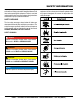
Safety Information Do not operate or service the equipment before reading the entire manual. Safety precautions should be followed at all times when operating this equipment. Failure to read and understand the safety messages and operating instructions could result in injury to yourself and others. Potential hazards associated with the operation of this equipment will be referenced with hazard symbols which may appear throughout this manual in conjunction with safety messages.
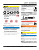
Safety Information general SaFeTY CauTion never operate this equipment without proper protective clothing, shatterproof glasses, respiratory protection, hearing protection, steel-toed boots and other protective devices required by the job or city and state regulations. never operate this equipment when not feeling well due to fatigue, illness or when under medication. never operate this equipment under the influence of drugs or alcohol.
Safety Information engine SaFeTY danger The engine fuel exhaust gases contain poisonous carbon monoxide. This gas is colorless and odorless, and can cause death if inhaled. The engine of this equipment requires an adequate free flow of cooling air. never operate this equipment in any enclosed or narrow area where free flow of the air is restricted. If the air flow is restricted it will cause injury to people and property and serious damage to the equipment or engine.
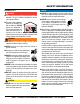
Safety Information Fuel SaFeTY danger do noT start the engine near spilled fuel or combustible fluids. Diesel fuel is extremely flammable and its vapors can cause an explosion if ignited. Make sure the hitch and coupling of the towing vehicle are rated equal to, or greater than the trailer “gross vehicle weight rating.” alWaYS inspect the hitch and coupling for wear. never tow a trailer with defective hitches, couplings, chains, etc.
Safety Information eleCTriCal SaFeTY danger do noT touch output terminals during operation. Contact with output terminals during operation can cause electrocution, electrical shock or burn. The electrical voltage required to operate the generator can cause severe injury or even death through physical contact with live circuits. Turn generator and all circuit breakers oFF before performing maintenance on the generator or making contact with output terminals.
Safety Information BaTTerY SaFeTY danger do noT drop the battery. There is a possibility that the battery will explode. do noT expose the battery to open flames, sparks, cigarettes, etc. The battery contains combustible gases and liquids. If these gases and liquids come into contact with a flame or spark, an explosion could occur. Warning environmenTal SaFeTY NOTICE Dispose of hazardous waste properly. Examples of potentially hazardous waste are used motor oil, fuel and fuel filters.
Specifications Model Type Armature Connection No of Poles Prime Output 1Ø Voltage 3Ø Voltages Frequency Voltage Regulation (no load to full load) Frequency Regulation (steady state load) Speed Power Factor Aux. AC Voltage Weight (Generator Only) Weight (Trailer Only) Dimensions (LxWxH) Model Emissions Type No. of Cylinders Bore x Stroke in (mm) Displacement Rated Output Starting Coolant Capacity Lube Oil Capacity Fuel Type Fuel Tank Capacity Fuel Consumption Table 1.
dimensions TOP VIEW A B Figure 1. Dimensions C D E F SIDE VIEW G I L K M FRONT VIEW AC VO LTS AC AMPERES AC AMPERES HERTZ AC AMPERES H J Table 4. Dimensions Reference Letter Dimensions in. (mm) Reference Letter Dimensions in. (mm) A 90 (2,286) H 130 (3,302) B 115 (2,921) I 22.5 (571) C 96 (2,438) J 23 (584) Chrome Wheels D 27 (686) J 24 (610) Aluminum Wheels E 24 (610) K 180 (4,572) F 24 (610) L 24.
installation GENERATOR GROUND LUG NOTE: GROUND LUG MUST BE INSTALLED BY USER. GROUND ROD FOR EARTH GROUND CONNECT TO BUILDING GROUND GROUND CABLE 8 FT. MINIMUM REFERENCE NEC 250-52(C) Figure 2. Typical Generator Grounding Application page 14 — SG1400C3 Studio Generator • operation manual — rev.
installation Outdoor Installation Generator Grounding Install the generator in a area that is free of debris, bystanders, and overhead obstructions. Make sure the generator is on secure level ground so that it cannot slide or shift around. Also install the generator in a manner so that the exhaust will not be discharged in the direction of nearby homes. To guard against electrical shock and possible damage to the equipment, it is important to provide a good EARTH ground.
general information Generator The MQ Power Model SG1400C3 is a 200kVA studio generator that is designed as a high quality power source for entertainment and studio applications. In keeping with Multiquip's policy of constantly improving its products, the specifications quoted herein are subject to change without prior notice. Permanent Magnet Generator Excitation System The SG1400C3 generator is equipped with a PMG (Permanent Magnet Generator) generator end.
general information Fuel Tank Interior Lighting This generator can be equipped with a 150 gallon (567 liters) fuel tank located beneath the trailer deck. The tank is made of steel (baffled). The tank can be filled from an external fill port located on the side of the trailer. The fill port has a 2-inch (51 mm) fill neck with vented cap. The interior lighting system is distributed throughout the interior. There are three separate lighting fixtures.
general information InteliVision 5 ™ Digital Controller The InteliVision 5 Digital Controller provides monitoring and fault detection capability of all engine and generator operating parameters.
Notes SG1400c3 studio generator • operation manual — rev.
Generator MAJOR COMPONENTS 1 3 4 2 14 6 16 15 5 7 13 30 31 12 32 33 11 9 10 8 17 18 Figure 3. Major Components 18 19 20 21 22 page 20 — SG1400C3 Studio Generator • operation manual — rev.
generator MAJOR COMPONENTS 28 29 23 34 Inside Housing 24 24 25 26 27 Figure 3. Major Components ITEM NO. 1 2 3 4 5 6 7 8 9 10 11 12 DESCRIPTION Muffler Air Filter Hydraulic Cylinders Coolant Overflow Bottle Charge Oil Cooler (Hydraulic) Charge Air Cooler Saddlebox 3 kVA Transformer Generator Fuel Gauge Fuel Cap, Vented Hydraulic Oil Filter Table 5. Generator Major Components ITEM DESCRIPTION NO.
BASIC ENGINE COMPONENTS 1 11 2 10 6 3 7 9 8 4 5 Figure 4. Basic Engine Components Table 6. Basic Engine Components ITEM NO. DESCRIPTION 1 Oil Filler Cap 2 Alternator 3 Oil Filter 4 Starter 5 Oil Drain Plug 6 Belt 7 Water Pump 8 Oil Dipstick 9 Fuel Filter 10 Fuel Rail 11 Turbocharger page 22 — SG1400C3 Studio Generator • operation manual — rev.
BASIC TRAILER COMPONENTS 1 2 3 12 4 5 6 7 8 9 10 11 14 13 16 19 18 15 17 Figure 5. Basic Trailer Components The definitions below describe the controls and functions of the Trailer (Figure 6). 1. Pintle Eye Coupler — Adjustable 3-inch eye coupler rated at 20,000 lbs. (9,072 kg). 2. Hydraulic Brake Actuator — Replaceable bolt-on actuator, assists in the stopping of the trailer. Rated at 12,000 lbs. (5,443 kg) 3.
control panel 2 3 4 1 13 12 8 7 11 6 14 5 15 9 10 16 17 Figure 6. Control Panel The definitions below describe the controls and functions of the Control Panel (Figure 6). 10. Controller Power Switch — Provides power to engine controller. 1. Voltage Adjust Switch — To increase the output voltage, pull upward and hold the switch until the desired voltage is achieved by monitoring the AC voltage display (item 8). To decrease the voltage, pull downward. 11.
camlok/voltage output panel 1 3 2 4 5 GREEN WHITE RED BLUE BLACK 6 7 7 8 8 9 Figure 7. Camlok/Voltage Output Panel The definitions below describe the controls and functions of the Camlok/Voltage Output Panel (Figure 7). 1. CB4/CB5 Circuit Breakers — These circuit breakers protect the 120 VAC auxiliary output receptacles from overload. 2. CB6/CB7 Circuit Breakers — These circuit breakers protect the bates output receptacles from overload. 3.
circuit Breaker panel 2 3 Electronic Trip Unit 450 AMP LONG — INST. Electronic Trip Unit Instantaneous Trip Setting - Amps Push to Trip 450 AMP LONG — INST. 1 Instantaneous Trip Setting - Amps Push to Trip D E F C G B A H A — 500 B — 600 C — 800 D — 1000 E — 1250 F — 1500 G — 2000 H — 2500 D E F C G B A H A — 500 B — 600 C — 800 D — 1000 E — 1250 F — 1500 G — 2000 H — 2500 Test Status Test Status 4 Figure 8.
digital controller 1 11 2 14 4 13 5 12 15 3 10 9 8 7 6 Figure 9. Digital Controller Refer to Figure 9 for location of controls and indicators. CONTROL BUTTONS 1. STATUS LED — Indicates status of the controller. Lights green when the controller is running. 11. START Button — Press button to go idle mode (about an hour) then generator starts. A second press will bypass idle mode and generator goes to full speed immediately. NAVIGATIONS BUTTONS 2.
load application/generator output Single Phase Load Three Phase Load Always be sure to check the nameplate on the generator and equipment to insure the wattage, amperage, frequency, and voltage requirements are satisfactorily supplied by the generator for operating the equipment. When calculating the power requirements for 3-phase power use the following equation. Generally, the wattage listed on the nameplate of the equipment is its rated output.
GENERATOR OUTPUTS Generator Output Voltages Generator Amperage A wide range of voltages are available to supply voltage for many different applications. Voltages are selected by using the voltage selector switch (Figure 10). To obtain some of the voltages as listed in Table 9 (see below) will require a fine adjustment using the voltage adjust toggle switch located on the digital control panel. Table 10 shows the maximum amps the generator can provide. DO NOT exceed the maximum amps as listed.
inspection/setup MAIN CIRCUIT BREAKER The generator is equipped with a 3-pole, 600-amp circuit breaker to protect the camlok receptacles from overload. Make sure that the main circuit breaker is in the OFF position prior to starting the engine. Lubrication Oil Fill the engine crankcase with lubricating oil through the filler hole, but DO NOT overfill. Make sure the generator is level and verify that the oil level is maintained between the two notches (Figure 11) on the dipstick.
inspection/setup 1. Place the generator level with the ground. Failure to do so will cause fuel to spill from the tank before reaching full capacity (Figure 12). 70 und ro el G ev Unl Level Ground = 1/2 E F DO NOT fill on unlevel ground ! ! d oun l Gr eve Unl Level Ground Figure 14. Full Fuel Tank CAUTION Figure 12. Only Fill on Level Ground NOTICE DO NOT OVERFILL fuel system. Leave room for fuel expansion. Fuel expands when heated (Figure 15). ONLY use #2 diesel fuel when refueling. 2.
inspection/setup Coolant (Antifreeze/summer coolant) Cleaning the Radiator Cummins recommends antifreeze/summer coolant, for use in their engines, which can be purchased in concentrate (and mixed with 50% demineralized water) or pre-diluted. See the Cummins Engine Owner’s Manual for further details. The engine may overheat if the radiator fins become overloaded with dust or debris. Periodically clean the radiator fins with compressed air.
inspection/setup Battery When connecting the battery do the following: This unit is of negative ground. DO NOT connect in reverse. Always maintain battery fluid level between the specified marks. DO NOT over fill. Battery life will be shortened if the fluid level is not properly maintained. Add only distilled water when replenishment is necessary. 1. Place a small amount of battery terminal treatment compound around both battery terminals.
startup Before Starting FUEL VALVES IN PRIME MODE CAUTION The engine’s exhaust contains harmful emissions. ALWAYS have adequate ventilation when operating. 1. Place the Control Power switch (Figure 18) on the digital control panel in the up position (ON). ON (UP) Figure 21. Fuel Valves (Prime Mode) ON (UP) Figure 18. Control Power Switch (ON) 2. Place the voltage selector switch (Figure 19) in the desired voltage setting position.
startup 6. If unit is to be used in parallel with another unit, interconnect the units. Interconnect the output buses with suitable power cables to carry full load capacity. Special male-to-male Camlok cables will be needed. For 480 V mode, it is recommended that one 4/0 cable per phase, neutral and ground be used. For 208V mode, use two 4/0 cables per phase and neutral and one 4/0 cable for ground. Also connect the parallel communication cables. 7.
startup 9. If paralleling to another unit and the bus was already energized from another unit (BUS HOT light already on), pressing to close GCB button once would initiate a synchronizing mode. The light above the button will begin flashing, bring the generator into phase and automatically close the breaker. Once the breaker closes, the light above the button would then become solid and the generators would now be in parallel. As load is applied, units will share the load proportionally. 1.
protective devices protective devices Protection devices and emergency stop devices are designed as standard components for protection of the generator against trouble during operation. The LCD on the Digital Controller will inform the user when a fault has occurred. When a major fault is detected, such as low oil pressure, high water temperature, and overspeed, the engine automatically shuts down. Check the display for the fault and correct the problem. For minor faults, the engine will continue working.
maintenance Use Table 14 as a general maintenance guideline when servicing your engine. For more detail engine maintenance information, refer to the engine owner’s manual supplied with your engine. Table 14.
maintenance General Inspection NOTICE Prior to each use, the generator should be cleaned and inspected for deficiencies. Check for loose, missing or damaged nuts, bolts, and other fasteners. Also check for fuel, oil, and coolant leaks. Use Table 14 as a general maintenance guideline. For engine maintenance, refer to the engine maintenance manual. The air filter should be changed more frequently in dusty operating conditions.
maintenance Fuel Tank Inspection In addition to cleaning the fuel tank, the following components should be inspected for wear: Rubber Suspension — look for signs of wear or deformity due to contact with oil. Replace the rubber suspension if necessary. Fuel Hoses — inspect nylon and rubber hoses for signs of wear, deterioration, and hardening. Fuel Tank Lining — inspect the fuel tank lining for signs of excessive amounts of oil and other foreign matter.
maintenance The following trailer maintenance guidelines are intended to assist the operator in preventive maintenance. Trailer Brakes 6. Replace the adjusting-hole cover. 7. Repeat the above procedure on all brakes. 8. Lower the trailer to the ground. Properly functioning brake shoes and drums are essential to ensure safety. The brakes should be inspected the first 200 miles of operation. This will allow the brake shoes and drums to seat properly.
maintenance WARNING Failure to maintain proper fluid level in the actuator may result in loss of braking action which could cause severe property damage, injury or death. Periodically check the actuator mounting fasteners for damage or loosening. Inspect the actuator for worn or damaged parts. As you are towing your trailer, be aware of any changes in braking quality. This could be an early warning of brake or actuator malfunction and requires immediate attention.
maintenance After removing the dust cap, cotter pin, spindle nut and spindle washer, remove the hub to inspect the bearings for wear and damage. Replace bearings that have flat spots on rollers, broken roller cages, rust or pitting. Always replace bearings and cups in sets. The inner and outer bearings are to be replaced at the same time. Replace seals that have nicks, tears or wear. Lubricate the bearings with a high quality EP-2 automotive wheel bearing grease.
troubleshooting (generator) Troubleshooting (Generator) Symptom No Voltage Output Low Voltage Output High Voltage Output Circuit Breaker Tripped Possible Problem Solution AC Voltmeter defective? Check output voltage using a voltmeter. Is wiring connection loose? Check wiring and repair. Is voltage regulator defective? Replace if necessary. Defective Rotating Rectifier? Check and replace. Defective Exciter Field? Check and replace.
troubleshooting (engine) Troubleshooting (Engine) Symptom Engine will not start or start is delayed, although engine can be turned over. At low temperatures engine will not start. Engine fires but stops soon as starter is switched off. Engine stops by itself during normal operation. Low engine power, output and speed. Possible Problem Solution No Fuel reaching injection pump? Add fuel. Check entire fuel system. Defective fuel pump? Replace fuel pump.
troubleshooting (controller) Troubleshooting (Intelivision 5 Controller) Symptom Possible Problem Solution Wrong Display HW SW and HW mismatch? Correct firmware has to be programmed. Invalidate configuration table Error Configuration table is invalid? Controller configuration has to be reprogrammed or upgraded. Unsupported controller Error Controller is not supported? Controller upgrade necessary. Unsupported cfg.
trailer guidelines The following guidelines are intended to assist the operator in the operation and handling of a trailer. Shift your automatic transmission into a lower gear for city driving. Safety precautions should be followed at all times when operating a trailer. Failure to read, understand and follow the safety guidelines could result in injury to yourself and others. Loss of control of the trailer or tow vehicle can result in death or serious injury.
trailer guidelines driving CondiTionS When towing a trailer, you will have decreased acceleration, increased stopping distance, and increased turning radius (which means you must make wider turns to keep from hitting curbs, vehicles, and anything else that is on the inside corner). In addition, you will need a longer distance to pass, due to slower acceleration and increased length. Be alert for slippery conditions.
trailer guidelines inoperaBle BraKeS, ligHTS or mirrorS Be sure that the brakes and all of the lights on your trailer are functioning properly before towing your trailer. Check the trailer taillights by turning on your tow vehicle headlights. Check the trailer brake lights by having someone step on the tow vehicle brake pedal while you look at trailer lights. Do the same thing to check the turn signal lights. See Trailer Wiring Diagram section in this manual.
trailer guidelines VI N TA G VIN TAG Figure B. VIN Tag Location The trailer VIN Tag contains the following critical safety information for the use of your trailer. To determine the “empty” or “net” weight of your trailer, weigh it on an axle scale. To find the weight of the trailer using an axle scale, you must know the axle weights of your tow vehicle without the trailer coupled.
trailer guidelines emergenCY FlareS and Triangle reFleCTorS Ball HiTCH Coupler It is wise to carry these warning devices even if you are not towing a trailer. It is particularly important to have these when towing a trailer because the hazard flashers of your towing vehicle will not operate for as long a period of time when the battery is running both the trailer lights and tow vehicle lights. A ball hitch coupler (Figure C) connects to a ball that is located on or under the rear bumper of tow vehicle.
trailer guidelines or is worn, the trailer can come loose from the tow vehicle and may cause death or serious injury. the trailer tongue. Wood or concrete blocks may also be used. THE TOW VEHICLE, HITCH AND BALL MUST HAVE A RATED TOWING CAPACITY EQUAL TO OR GREATER THAN THE TRAILER gross vehicle Weight rating (gvWr). IT IS ESSENTIAL THAT THE HITCH BALL BE OF THE SAME SIZE AS THE COUPLER.
trailer guidelines Breakaway Brake System NOTICE Overloading can damage the tongue jack. do noT use the tongue jack to raise the tow vehicle more than one inch. If the coupler cannot be secured to the hitch ball, do not tow the trailer. Call your dealer for assistance. Lower the trailer so that its entire tongue weight is held by the hitch and continue retracting the jack to its fully retracted position.
trailer guidelines Connecting Trailer lights pinTle HiTCH Coupler Connect the trailer lights to the tow vehicle’s electrical system using the electric connectors at the front of the trailer (tongue). Refer to the wiring diagram shown in the trailer wiring diagram section of this manual. Before towing the trailer check for the following: A pintle eye coupler (Figure G) connects to a pintle-hook hitch that is located on or under the rear bumper of the tow vehicle.
trailer guidelines the ball andcoupler system. All bent or broken coupler parts must be replaced before towing the trailer. THE TOW VEHICLE, PINTLE HITCH AND PINTLE COUPLER MUST HAVE A RATED TOWING CAPACITY EQUAL TO OR GREATER THAN THE TRAILER gross vehicle Weight rating (gvWr). IT IS ESSENTIAL THAT THE PINTLE HITCH BE OF THE SAME SIZE AS THE PINTLE COUPLER. The coupler size and load rating (capacity) are marked on the coupler. Hitch capacity is marked on the hitch.
trailer guidelines Tire SaFeTY unsafe Tires, lug nuts or Wheels Trailer tires and wheels are more likely to fail than car tires and wheels because they carry a heavier load. Therefore, it is essential to inspect the trailer tires before each tow. If a tire has a bald spot, bulge, cuts, is showing any cords, or is cracked, replace the tire before towing. If a tire has uneven tread wear, take the trailer to a dealer service center for diagnosis.
trailer guidelines There is a vehicle placard (Figure I) located in the same location as the certification label described above. This placard provides tire and loading information. In addition, this placard will show a statement regarding maximum cargo capacity. TIRE AND LOADING INFORMATION The weight of cargo should never exceed XXX kg. Or XXX lbs. TIRE FRONT REAR SPARE SIZE COLD TIRE PRESSURE SEE OWNER’S MANUAL FOR ADDITIONAL INFORMATION Figure I.
trailer guidelines Use the information contained in this section to make tire safety a regular part of your vehicle maintenance routine. Recognize that the time you spend is minimal compared with the inconvenience and safety consequences of a flat tire or other tire failure. Tire FundamenTalS Federal law requires tire manufacturers to place standardized information on the sidewall of all tires (Figure J).
trailer guidelines uniform Tire Quality grading Standards (uTQgS) Treadwear number: This number indicates the tire’s wear rate. The higher the treadwear number is, the longer it should take for the tread to wear down. For example, a tire graded 400 should last twice as long as a tire graded 200. Traction letter: This letter indicates a tire’s ability to stop on wet pavement. A higher graded tire should allow you to stop your car on wet roads in a shorter distance than a tire with a lower grade.
trailer guidelines Table B below will help pinpoint the causes and solutions of tire wear problems. Table B. Tire Wear Troubleshooting Wear pattern Cause Solution Center Wear Over inflation. Adjust pressure to particular load per tire manufacturer. Edge Wear Under inflation. Adjust pressure to particular load per tire manufacturer. Side Wear Loss of camber or overloading. Make sure load does not exceed axle rating. Align wheels. Toe Wear Incorrect toe-in. Align wheels.
trailer guidelines Table C. Tire Torque requirements Wheel Size First pass FT-lBS Second pass FT-lBS Third pass FT-lBS 12" 20-25 35-40 50-65 13" 20-25 35-40 50-65 14" 20-25 50-60 90-120 15" 20-25 50-60 90-120 16" 20-25 50-60 90-120 Replace any broken or burned-out lamps as necessary. Check the wire harness for cuts, fraying or other damage. If it needs replacing, contact your dealer. Warning Improper operating taillights, stoplights and turn signals can cause collisions.
Operation Manual HERE’S HOW TO GET HELP PLEASE HAVE THE MODEL AND SERIAL NUMBER ON-HAND WHEN CALLING United StateS Multiquip Corporate Office 18910 Wilmington Ave. Carson, CA 90746 Contact: mq@multiquip.com MQ Parts Department Tel.