OPERATION & PARTS MANUAL SERIES MODEL MVH-R60H REVERSABLE PLATE COMPACTOR (HONDA GASOLINE ENGINE) Revision #1 (09/09/04) THIS MANUAL MUST ACCOMPANY THE EQUIPMENT AT ALL TIMES.
l PAGE 2 — MVH-R60H— OPERATION AND PARTS MANUAL — REV.
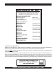
HERE'S HOW TO GET HELP PLEASE HAVE THE MODEL AND SERIAL NUMBER ON-HAND WHEN CALLING MULTIQUIP CORPORATE OFFICE 18910 Wilmington Ave. Carson, CA 90746 Email: mq@multiquip.com Internet: www.multiquip.com PARTS DEPARTMENT 800-427-1244 310-537-3700 MAYCO PARTS 800-306-2926 310-537-3700 SERVICE DEPARTMENT 800-478-1244 310-537-3700 TECHNICAL ASSISTANCE 800-421-1244 WARRANTY DEPARTMENT 800-421-1244, EXT. 279 310-537-3700, EXT.
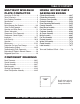
TABLE OF CONTENTS MULTIQUIP MVH-R60H PLATE COMPACTOR HONDA GX120K1SM12 GASONLINE ENGINE Here's How To Get Help .............................................3 Table Of Contents ......................................................4 Parts Ordering Procedures ........................................5 Specifications .............................................................6 Dimensions ................................................................7 Safety Message Alert Symbols ..........................
PARTS ORDERING PROCEDURES When ordering parts, please supply the following information: ❒ ❒ ❒ ❒ ❒ ❒ ❒ Dealer account number Dealer name and address Shipping address (if different than billing address) Return fax number Applicable model number Quantity, part number and description of each part Specify preferred method of shipment: Note: Unless otherwise indicated by customer, all ✓ FedEx or UPS Ground orders are treated as “Standard Orders”, and will ✓ FedEx or UPS Second Day or Third Day ship within 24 hou
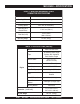
MVH-R60H — SPECIFICATIONS TABLE 1. MVH-R60H REVERSIBLE PLATE COMPACTOR SPECIFICATIONS Model MVH-R60H Centrifugal Force 3,100 lbs. (1,400 kg.) Number of Vibrations 6,000 v/min. Traveling Speed 82 ft./min (25 meters/min.) Lubricating Oil in Vibration Case 17.92 fl. oz. (530 cc.) Plate Size (LxW) 18.9 x 13.8 in. (480 x 350 mm.) Operating Weight 141 lbs. (64 kg.) TABLE 2.
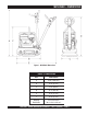
MVH-R60H — DIMENSIONS Figure 1. MVH-R60H Dimensions TABLE 3. DIMENSIONS REF. DIMENSIONS A 45 in. (134.6 cm.) B 22 in. (61 cm.) C 13 in. (86 cm.) D 41 in. (162 cm.) E 35 in. (97 cm.) F 25 in. (97 cm.) Shipping Dimensions: 14.5 x 23 x 43 in. (36.8 x 58.4 x 109 cm.) MVH-R60H —OPERATION AND PARTS MANUAL — REV.
MVH-R60H — SAFETY MESSAGE ALERT SYMBOLS FOR YOUR SAFETY AND THE SAFETY OF OTHERS! Safety precautions should be followed at all times when operating this equipment. Failure to read and understand the Safety Messages and Operating Instructions could result in injury to yourself and others. This Owner's Manual has been developed to provide complete NOTE instructions for the safe and efficient operation of the Multiquip MVC-R60H Plate Compactor.
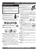
MVH-R60H — SAFETY MESSAGE ALERT SYMBOLS CAUTION - Rotating Parts CAUTION - Equipment Damage Messages NEVER operate equipment with covers, or guards removed. Keep fingers, hands, hair and clothing away from all moving parts to prevent injury. Other important messages are provided throughout this manual to help prevent damage to your light tower, other property, or the surrounding environment.
MVH-R60H — RULES FOR SAFE OPERATION WARNING - Read This Manual Failure to follow instructions in this manual may lead to Serious Injury or even Death. This equipment is to be operated by trained and qualified personnel only! This equipment is for industrial use only. The following safety guidelines should always be used when operating the Mikasa MVH-R60H Reversible Plate Compactor: Safety: ■ DO NOT operate or service this equipment before reading this entire manual.
MVH-R60H — RULES FOR SAFE OPERATION Loading and Unloading (Crane): ■ Before lifting, make sure that machine parts (hook and vibration insulator) are not damaged and screws are not loosened or lost. ■ Always make sure crane or lifting device has been properly secured to the hook of guard frame on compactor. ■ NEVER lift the machine while the engine is running. ■ Use adequate lifting cable (wire or rope) of sufficient strength. ■ Use one point suspension hook and lift straight upwards.
MVH-R60H — OPERATION AND SAFETY DECALS Machine Safety Decals The MVH-R60H Reversible Plate Compactor is equipped with a number of safety decals. These decals are provided for operator safety and maintenance information. The illustration below shows these decals as they appear on the machine. Should any of these decals become unreadable, replacements can be obtained from your dealer. l Figure 2. Operation and Safety Decals PAGE 12 — MVH-R60H— OPERATION AND PARTS MANUAL — REV.
MVH-R60H — FEATURES Definition of Plate Compactor Frequency/Speed The Mikasa MVH-R60H is a walk-behind, reversible plate compactor design for the compaction of sand, clay and asphalt. This plate compactor is a powerful compacting tool capable of applying a tremendous force in consecutive high frequency vibrations to a soil surface. Its applications include soil compacting for road, embankments and reservoirs as well as backfilling for gas pipelines, water pipelines and cable installation work.
MVH-R60H — COMPONENTS (PLATE COMPACTOR) Figure 3. Compactor Controls Figure 3 shows the location of the controls, indicators and general maintenance parts. The function of each control is described below: 1. Breather Cap – Remove this cap to bleed (remove air) the hydraulic system. When replacing hydraulic oil, use "Shell Tellus #46 or equivalent". 2. Hand Grip – When operating the compactor use this hand grip to manuever the compactor. l 3.
MVH-R60H — COMPONENTS (HONDA GX120K1SM12 ENGINE) Figure 4. Honda GX160K1QA2 Engine Controls & Components INITIAL SERVICING The engine (Figure 4) must be checked for proper lubrication and filled with fuel prior to operation. Refer to the manufacturer's Engine manual for instructions & details of operation and servicing. 6. Choke Lever – Used in the starting of a cold engine, or in cold weather conditions.The choke enriches the fuel mixture. 7.
MVH-R60H — INSPECTION CAUTION - General Safety Precautions NEVER operate the compactor in a confined area or enclosed area structure that does not provide ample free flow of air. 3. Insert and remove the dipstick without screwing it into the filler neck. Check the oil level shown on the dipstick. 4. If the oil level is low (Figure 6), fill to the edge of the oil filler hole with the recommended oil type (Table 4). Maximum oil capacity is 400 cc.
MVH-R60H — START-UP PROCEDURE This section is intended to assist the operator with the initial start-up of the compactor. It is extremely important that this section be read carefully before attempting to use the compactor D in the field. 1. Place the fuel valve lever (Figure 7) in the ON position. 4. Place the throttle lever halfway between FAST and SLOW. This compactor is equipped with a throttle lever (Figure 10) that is located in the vicinity of the hydraulic pump.
MVH-R60H — SHUT-DOWN PROCEDURES Emergency Shutdown Proucedure: Stopping the Engine CAUTION - Stopping the engine while working NEVER stop the engine suddenly while working at high speeds. This can damage your engine. 1. Move the throttle lever quickly to the SLOW position (Figure 12). 2. Place the engine ON/OFF switch in the OFF position (Figure 13). 1. Place the throttle lever (Figure 12) in SLOW position, and listen for the engine speed to decrease. Figure 12. Throttle Lever (SLOW Position) 2.
MVH-R60H — OPERATION Operation CAUTION - Directional Travel Lever Lock CAUTION - General Operation Safety Make sure to follow all safety rules referenced in the safety section of this manual before operating compactor. Keep work area clear of debris and other objects that could cause damage to the compactor or bodily injury. 1. Grasp the compactor's hand grip and move the throttle lever (Figure 10) quickly to the fast position.
MVH-R60H — MAINTENANCE Maintenance TABLE 6. MACHINE INSPECTION CAUTION - General Maintenance Safety Inspection and other services should always be carried out on hard and level ground with the engine shutdown. Inspection and Maintenance Service Tables. To make sure your plate compactor is always in good working condition before using, carry out the maintenance inspection in accordance with Tables 5 through 7. Daily Service z Check for leakage of fuel or oil. z Check for loose screws including tightness.
MVH-R60H — MAINTENANCE Spark Plug Air Filter 1. Remove and clean the spark plug (Figure 16). The air filter element should be regularly cleaned. A clogged air cleaner can cause poor engine starting, lack of power and shorten engine life substantially. 2. Adjust the spark gap to 0.028 ~0.031 inch (0.6~0.7 mm). This unit has electronic ignition, which requires no adjustments. 1.
MVH-R60H — MAINTENANCE Checking and Replacing the V-Belt and Clutch CAUTION - Checking and Replacing the V-Belt NEVER attempt to check the V-belt with the engine running. Severe injury can occur if your hand gets caught between the V-belt and the clutch. Always use safety gloves. 1. To check the V-belt tension (Figure 19), remove upper belt cover. Replacing the V-belt 1. Remove the belt cover. 2. Engage an offset wrench (13 mm) or the like to vibrator pulley (lower) fastening bolt. 3.
MVH-R60H — INSPECTION Hydraulic Oil Check Check hydraulic oil in every 100 hours of operation. 1. With handle bar positioned vertically (storage position), remove the breather cap (Figure 8) from the breather plug. 2. Use a 24 mm wrench and remove breather plug (Figure 21). Visually check to see if hydraulic oil comes up to the oil level line that is etched on the back side of the handle. CAP BREATHER PLUG 5. Replace breather plug of hand pump and fit the plug cap.
MVH-R60H — TROUBLESHOOTING (ENGINE) Practically all breakdowns can be prevented by proper handling and maintenance inspections, but in the event of a breakdown, please take a remedial action following the diagnosis based on the Engine Troubleshooting (Tables 8) information shown below and on the proceeding pages. If the problem cannot be remedied, please leave the unit just as it is and consult our company's business office or service plant. TABLE 8.
MVH-R60H — TROUBLESHOOTING (ENGINE) TABLE 8. ENGINE TROUBLESHOOTING (CONTINUED) SYMPTOM "Weak in power" compression is proper and does not misfire. "Weak in power" compression is proper but misfires. Engine overheats. Rotational speed fluctuates. POSSIBLE CAUSE SOLUTION Air cleaner not clean? Clean or replace air cleaner Improper level in carburetor? Check float adjustment, re-build carbureator. Defective Spark plug? Clean or replace spark plug.
MVH-R60H — TROUBLESHOOTING (PLATE COMPACTOR) Practically all breakdowns can be prevented by proper handling and maintenance inspections, but in the event of a breakdown, please take a remedial action following the diagnosis based on the Compactor Troubleshooting (Tables 9) information shown below and on the proceeding pages. If the problem cannot be remedied, please leave the unit just as it is and consult our company's business office or service plant. TABLE 9.
NOTE PAGE MVH-R60H —OPERATION AND PARTS MANUAL — REV.
MVH-R60H — EXPLANATION OF CODE IN REMARKS COLUMN How to read the marks and remarks used in this parts book. Items Found In the “Remarks” Column Serial Numbers-Where indicated, this indicates a serial number range (inclusive) where a particular part is used. Model Number-Where indicated, this shows that the corresponding part is utilized only with this specific model number or model number variant.
MVH-R60H — SUGGESTED SPARE PARTS MVH-R60H with HONDA GX120K1SM12 ENGINE 1 to 5 Units Qty. P/N Description 3 ......... 070100312 ....... V-BELT 4 ......... 939010250 ....... SHOCK ABSORBER 3 ......... 9807956846 ..... SPARK PLUG 1 ......... 28462ZH8003 ... ROPE, RECOIL STARTER 3 ......... 17210ZE0822 ... ELEMENT, AIR CLEANER 1 ......... 17620ZH7023 ... FUEL CAP 1 ......... 17672ZE2W01 . FUEL FILTER, FUEL TANK MVH-R60H —OPERATION AND PARTS MANUAL — REV.
MVH-R60H — NAME PLATES AND DECALS NAME PLATES ASSY. l PAGE 30 — MVH-R60H— OPERATION AND PARTS MANUAL — REV.
MVH-R60H — NAME PLATES AND DECALS NAMEPLATE AND DECALS NO PART NO 1 920201580 2 920207480 3 4 920110000 5 920207420 6 920209520 7 920201650 PART NAME QTY. REMARKS DECAL, MQ MARK 71X55 1 DECAL, SHELL TELLUS OIL 46 1 DECAL, SERIAL NO. ...................................... 1 ................ CONTACT PARTS DEPT. DECAL, MVH-R60 1 DECAL, V-BELT RPF-3320 1 DECAL, OPERATIONAL CAUTION 1 DECAL, OIL SAE 10W30 1 MVH-R60H —OPERATION AND PARTS MANUAL — REV.
MVH-R60H — CONTROL HANDLE ASSY. CONTROL HANDLE ASSY. l PAGE 32 — MVH-R60H— OPERATION AND PARTS MANUAL — REV.
MVH-R60H — CONTROL HANDLE ASSY. CONTROL HANDLE ASSY.
MVH-R60H — CONTROL HANDLE ASSY. (CONTINUED) CONTROL HANDLE ASSY. (CONTINUED) l PAGE 34 — MVH-R60H— OPERATION AND PARTS MANUAL — REV.
MVH-R60H — CONTROL HANDLE ASSY. (CONTINUED) CONTROL HANDLE ASSY.
MVH-R60H — VIBRATOR ASSY. VIBRATOR ASSY. l PAGE 36 — MVH-R60H— OPERATION AND PARTS MANUAL — REV.
MVH-R60H — VIBRATOR ASSY. VIBRATOR ASSY.
MVH-R60H — BODY ASSY. BODY ASSY. l PAGE 38 — MVH-R60H— OPERATION AND PARTS MANUAL — REV.
MVH-R60H — BODY ASSY. BODY NO 1 1 ASSY.
MVH-R60H — BODY ASSY. BODY ASSY. l PAGE 40 — MVH-R60H— OPERATION AND PARTS MANUAL — REV.
MVH-R60H — BODY ASSY. BODY NO 36 37 38 39 41 42 43 44 45 46 47 48 ASSY. PART NO 458450810 001220825 031108160 022710809 15550ZK8P90 15552ZB9000 954010070 90601ZE1000 90131ZE1000 458450840 001220820 030208200 PART NAME PLATE, RUBBER COVER BOLT 8X25 T WASHER, FLAT M8 NYLON NUT M8 DRAIN JOINT DRAIN HOSE HOSE BAND 11.5D WASHER, DRAIN PLUG BOLT, DRAIN PLUG JOINT BOLT 8X20 T WASHER, LOCK M8 QTY. 1 2 2 2 2 1 2 3 1 1 1 1 REMARKS MVH-R60H —OPERATION AND PARTS MANUAL — REV.
MVH-R60H — VIBRATING PLATE ASSY. VIBRATING PLATE ASSY. l PAGE 42 — MVH-R60H— OPERATION AND PARTS MANUAL — REV.
MVH-R60H — VIBRATING PLATE ASSY. VIBRATING PLATE ASSY. NO PART NO 1 463117110 2 939010160 3 020310080 4 030210250 5 001221030 6 030210250 7 952401660 9 460449160 10 953405260 PART NAME VIBRATING PLATE SHOCK ABSORBER TAK-50 NUT M10 WASHER, LOCK M10 BOLT 10X30 T WASHER, LOCK M10 WASHER 103045 OIL GAUGE PACKING 1/4 (CU) QTY. 1 4 4 4 4 4 4 1 1 REMARKS MVH-R60H —OPERATION AND PARTS MANUAL — REV.
MVH-R60H — WATER TANK/SPRINKLER ASSY. WATER TANK/SPRINKLER ASSY. l PAGE 44 — MVH-R60H— OPERATION AND PARTS MANUAL — REV.
MVH-R60H — WATER TANK/SPRINKLER ASSY. WATER TANK/SPRINKLER ASSY. NO PART NO PART NAME QTY. REMARKS 1 001241030 BOLT 10 X30 1 * 033910010 WASHER 10 MM 5 X 21 X 2 2 2 * 3 CAP, WATER TANK 1 * 954300342 4 463456580 WATER HOSE 1 5 NYLON NUT M10 1 * 022910180 6 022610808 FLANGE NUT M8 1 7 463910010 WATER TANK ASSY. ........................................... 1 .............
HONDA GX120K1SM12 ENGINE — CYLINDER HEAD ASSY. CYLINDER HEAD ASSY. l PAGE 46 — MVH-R60H— OPERATION AND PARTS MANUAL — REV.
HONDA GX120K1SM12 ENGINE — CYLINDER HEAD ASSY. CYLINDER HEAD ASSY. NO. 1 2 * 3 * 4 + * 5 6 7 8 9 10 11 12 14 15 PART NO. 12210ZH7000 12204ZE1306 12205ZE1315 12216ZE5300 12251ZH7800 12310ZE1020 12391ZE1000 15721ZH8000 90013883000 90043ZE1020 90047ZE1000 9430110160 957230805500 9807956846 PART NAME QTY. REMARKS CYLINDER HEAD .................................................. 1 .............. INCLUDES ITEMS W/ * GUIDE, VALVE (OS) OPTIONAL 1 GUIDE, EX. VALVE (OS) OPTIONAL ................... 1 ..............
HONDA GX120K1SM12 ENGINE — CYLINDER BARREL ASSY. CYLINDER BARREL ASSY. l PAGE 48 — MVH-R60H— OPERATION AND PARTS MANUAL — REV.
HONDA GX120K1SM12 ENGINE — CYLINDER BARREL ASSY. CYLINDER BARREL ASSY. NO. 2 3 4 5# 6# 7# 8 9 10 11 12 13 14 * 15 * 16 17 18 19 20 PART NO. 120A0ZH7810 15510ZE1033 16510ZE1000 16511ZE1000 16512ZE1000 16513ZE1000 16531ZE1000 16541ZE1000 90131ZE1000 90451ZE1000 90601ZE1000 90602ZE1000 91001878003 91202ZE6003 91353671004 9405010000 9410106800 9425108000 957010601200 PART NAME QTY. REMARKS BARREL ASSY., CYLINDER ......................1 ............ INCLUDES ITEMS W/ * SWITCH ASSY., OIL LEVEL 1 GOVERNOR ASSY.
HONDA GX120K1SM12 ENGINE — CRANKCASE COVER ASSY. CRANKCASE COVER ASSY. l PAGE 50 — MVH-R60H— OPERATION AND PARTS MANUAL — REV.
HONDA GX120K1SM12 ENGINE — CRANKCASE COVER ASSY. CRANKCASE COVER ASSY. NO. 1 3 5 6 11#+ 15 17 * 18 * 21 PART NO. 11300ZE0640 11381ZH7800 15600ZE1003 15600ZG4003 15625ZE1003 90015883000 91001878003 91203ZE0003 9430108140 PART NAME QTY. REMARKS COVER ASSY., CRANKCASE ................................ 1 .............. INCLUDES ITEMS W/ * GASKET, CRANKCASE 1 CAP ASSY., OIL FILLER ......................................... 1 ..............INCLUDES ITEMS W/# CAP ASSY., OIL FILLER .................................
HONDA GX120K1SM12 ENGINE — CRANKSHAFT ASSY. CRANKSHAFT ASSY. l PAGE 52 — MVH-R60H— OPERATION AND PARTS MANUAL — REV.
HONDA GX120K1SM12 ENGINE — CRANKSHAFT ASSY. CRANKSHAFT ASSY. NO. 1 PART NO. 13310ZE0601 PART NAME CRANKSHAFT QTY. 1 REMARKS MVH-R60H —OPERATION AND PARTS MANUAL — REV.
HONDA GX120K1SM12 ENGINE — PISTON/CONNECTING ROD ASSY. PISTON/CONNECTING RODASSY. l PAGE 54 — MVH-R60H— OPERATION AND PARTS MANUAL — REV.
HONDA GX120K1SM12 ENGINE — PISTON/CONNECTING ROD ASSY. PISTON/CONNECTING RODASSY. NO. 1 1 1 1 2 2 2 2 3 4 4 5 * 6 PART NO. 13010ZK7V01 13011ZK7V01 13012ZK7V01 13013ZK7V01 13101ZH7000 13102ZH7000 13103ZH7000 13104ZH7000 13111ZE0000 132A0ZE0000 13200ZE0000 90001ZE1000 90551ZE0000 PART NAME QTY. REMARKS RING SET, PISTON (STANDARD) 1 RING SET, PISTON (OS 0.25), OPTIONAL 1 RING SET, PISTON (OS 0.50) , OPTIONAL 1 RING SET, PISTON (OS 0.75), OPTIONAL 1 PISTON, STANDARD 1 PISTON, OS 0.25 1 PISTON, OS 0.
HONDA GX120K1SM12 ENGINE — CAMSHAFT ASSY. CAMSHAFT ASSY. l PAGE 56 — MVH-R60H— OPERATION AND PARTS MANUAL — REV.
HONDA GX120K1SM12 ENGINE — CAMSHAFT ASSY. CAMSHAFT ASSY. NO. 1 2 3 4 5 6 * 7 8 9 10 11 12 13 14 15 PART NO. 14100ZE0812 14410ZE0010 14431ZE1000 14441ZE1010 14451ZE1013 14568ZE1000 14711ZF0000 14721ZF0000 14751ZF1000 14771ZE1000 14773ZE1000 14781ZE1000 14791ZE0010 90012ZE0010 90206ZE1000 PART NAME QTY. REMARKS CAMSHAFT ASSY. .......................................... 1............. INCLUDES ITEMS W/ * ROD, PUSH 2 ARM, VALVE ROCKER 2 LIFTER, VALVE 2 PIVOT, ROCKER ARM 2 SPRING, WEIGHT RETURN 1 VALVE, IN.
HONDA GX120K1SM12 ENGINE — RECOIL STARTER ASSY. RECOIL STARTER ASSY. l PAGE 58 — MVH-R60H— OPERATION AND PARTS MANUAL — REV.
HONDA GX120K1SM12 ENGINE — RECOIL STARTER ASSY. RECOIL STARTER ASSY. NO. 1 2 * 3 * 4 * 5 * 6 * 7 * 8 * 9 * 10 * 11 * 12 PART NO. 28400ZH8013ZA 28410ZH8003ZA 28420ZH8013 28422ZH8013 28433ZH8003 28441ZH8003 28442ZH8003 28443ZH8003 28461ZH8003 28462ZH8003 90003ZH8003 9008ZE2003 PART NAME QTY. REMARKS STARTER ASSY., RECOIL *NH1* (BLACK) .......... 1 ..............
HONDA GX120K1SM12 ENGINE — FAN COVER ASSY. FAN COVER ASSY. l PAGE 60 — MVH-R60H— OPERATION AND PARTS MANUAL — REV.
HONDA GX120K1SM12 ENGINE — FAN COVER ASSY. FAN COVER ASSY. NO. 1 2 3 4 5 6 7 8 9 10 11 13 PART NO. 11347371300 19610ZE0000ZA 19611ZH7810 90601ZH7013 19630ZH7000 32197ZH8003 36100ZH7003 36101ZE1010 90013883000 90022888010 34150ZH7003 95 7010600800 PART NAME GROMMET, ADJUSTING COVER COVER, FAN RED PLATE, SIDE (OIL ALERT) CLIP, HARNESS SHROUD SUB- HARNESS SWITCH ASSEMBLY, ENGINE STOP WIRE, STOP SWITCH 370MM BOLT, FLANGE 6X12 (CT200) BOLT, FLANGE 6X12 (CT200) ALERT UNIT, OIL BOLT, FLANGE 6X8 QTY.
HONDA GX120K1SM12 ENGINE — CARBURETOR ASSY. CARBURETOR ASSY. l PAGE 62 — MVH-R60H— OPERATION AND PARTS MANUAL — REV.
HONDA GX120K1SM12 ENGINE — CARBURETOR ASSY. CARBURETOR ASSY. NO. 2 # * 3 * 4 * 5 * 7 # * 8 * 9 * 10 11 * 12 * 13 * 14 15 16 17 20 24 * 25 * 26 * 27 * 28 * 30 * 33+ 34 * 35 * 36 PART NO.
HONDA GX120K1SM12 ENGINE — AIR CLEANER ASSY. AIR CLEANER ASSY. l PAGE 64 — MVH-R60H— OPERATION AND PARTS MANUAL — REV.
HONDA GX120K1SM12 ENGINE — AIR CLEANER ASSY. AIR CLEANER ASSY. NO. 1 2 3# 4 5# 6 7 * 8 * 9 12 13 14 15 PART NO. 16271ZE1000 17210ZE0822 17218ZE0821 17230ZE0820 17232891000 17235ZE1831 17238ZE0010 17239ZE1000 17410ZE0030 90325044000 957010602000 9405006000 9410106800 PART NAME QTY. REMARKS GASKET, ELBOW 1 CLEANER ELEMENT ......................................... 1...........
HONDA GX120K1SM12 ENGINE — MUFFLER ASSY. MUFFLER ASSY. l PAGE 66 — MVH-R60H— OPERATION AND PARTS MANUAL — REV.
HONDA GX120K1SM12 ENGINE — MUFFLER ASSY. MUFFLER ASSY. NO. 1 3 5 6 7 10 13 14 18 19 PART NO. 18310ZH8810 18320ZF1H01 18340ZE1010 18355ZE1000 18381ZH8800 90050ZE1000 94001080000S 18522ZE1000 90055ZE1000 90002ZG0003 PART NAME MUFFLER, ARRESTER PROTECTOR, MUFFLER DEFLECTOR ARRESTER, SPARK GASKET, MUFFLER SCREW, TAPPING 5X8 NUT, HEX. 8MM GUIDE, MUFFLER SCREW, TAPPING 4X6 SCREW, TAPPING 4X8 QTY. 1 1 1 REMARKS 1 4 2 1 1 2 MVH-R60H —OPERATION AND PARTS MANUAL — REV.
HONDA GX120K1SM12 ENGINE — FUEL TANK ASSY. FUEL TANK ASSY. l PAGE 68 — MVH-R60H— OPERATION AND PARTS MANUAL — REV.
HONDA GX120K1SM12 ENGINE — FUEL TANK ASSY. FUEL TANK ASSY. NO. 1 2 3 5 6 * 7 11 12 13 14 15 PART NO. 16854ZH8000 16955ZE1000 17510ZE0020ZD 17620ZH7023 17631ZH7003 17672ZE2W01 91353671004 9405006000 950014514040 9500202080 957010602500 PART NAME QTY. REMARKS RUBBER, SUPPORTER 107MM 1 JOINT, FUEL TANK 1 TANK, FUEL *NH1* (BLACK) 1 CAP, FUEL FILLER ...................................... 1 .......... INCLUDES ITEMS W/ * GASKET, FUEL FILLER CAP 1 FUEL FILTER 1 O- RING 14MM 1 NUT, FLANGE 6MM 2 BULK HOSE, FUEL 4.
HONDA GX120K1SM12 ENGINE — FLYWHEEL ASSY. FLYWHEEL ASSY. l PAGE 70 — MVH-R60H— OPERATION AND PARTS MANUAL — REV.
HONDA GX120K1SM12 ENGINE — FLYWHEEL ASSY. FLYWHEEL ASSY. NO. 1 2 4 5 7 PART NO. 13331357000 19511ZE0000 28451ZH8003 31100ZE0010 90201878003 PART NAME KEY, SPECIAL WOODRUFF 25X18 FAN, COOLING PULLEY, STARTER FLYWHEEL NUT, SPECIAL 14MM QTY. 1 1 1 1 1 REMARKS MVH-R60H —OPERATION AND PARTS MANUAL — REV.
HONDA GX120K1SM12 ENGINE — IGNITION COIL ASSY. IGNITION COIL ASSY. l PAGE 72 — MVH-R60H— OPERATION AND PARTS MANUAL — REV.
HONDA GX120K1SM12 ENGINE — IGNITION COIL ASSY. IGNITION COIL ASSY. NO. 1 2 8 PART NO. 30500ZE1033 30700ZE1013 90121952000 PART NAME COIL ASSY., IGNITION CAP ASSY., NOISE SUPPRESSOR BOLT, FLANGE 6X25 QTY. 1 1 2 REMARKS MVH-R60H —OPERATION AND PARTS MANUAL — REV.
HONDA GX120K1SM12 ENGINE — CONTROL ASSY. CONTROL ASSY. l PAGE 74 — MVH-R60H— OPERATION AND PARTS MANUAL — REV.
HONDA GX120K1SM12 ENGINE — CONTROL ASSY. CONTROL ASSY. NO. 2 5 6 7 8 9# 10# 11# 12# 13# 15# 16# 17# 18# 22 23 25 26# 28# 30# 32# 33 PART NO. 16500ZH7810 16551ZE0010 16555ZE0000 16561ZE0020 16562ZE0020 16571ZH7000 16574ZE1000 16575ZH8000 16576891000 16578ZE1000 16580ZH7810 16584883300 16592ZE1810 16594883010 90013883000 90015ZE5010 90022888010 90114SA0000 93500040060H 93500050250H 93500050160A 9405006000 PART NAME QTY. REMARKS CONTROL ASSY. ...................................... 1 ............
HONDA GX120K1SM12 ENGINE — LABELS ASSY. LABELS ASSY. l PAGE 76 — MVH-R60H— OPERATION AND PARTS MANUAL — REV.
HONDA GX120K1SM12 ENGINE — LABELS ASSY. LABELS ASSY. NO. 1 3 4 6 PART NO. 87521ZH7020 87522ZH9000 87528ZE1810 87532ZH8810 PART NAME EMBLEM LABEL, CAUTION MARK, CHOKE MARK, OIL ALERT (E) QTY. 1 1 1 1 REMARKS MVH-R60H —OPERATION AND PARTS MANUAL — REV.
TERMS AND CONDITIONS OF SALE — PARTS Effective: October 1, 2002 PAYMENT TERMS 5. Parts must be in new and resalable condition, in the original Multiquip package (if any), and with Multiquip part numbers clearly marked. 6. The following items are not returnable: Terms of payment for parts are net 10 days. FREIGHT POLICY All parts orders will be shipped collect or prepaid with the charges added to the invoice. All shipments are F.O.B. point of origin.
NOTE PAGE MVH-R60H —OPERATION AND PARTS MANUAL — REV.
OPERATION & PARTS MANUAL HERE'S HOW TO GET HELP PLEASE HAVE THE MODEL AND SERIAL NUMBER ON-HAND WHEN CALLING MULTIQUIP CORPORATE OFFICE 18910 Wilmington Ave. Carson, CA 90746 Email: mq@multiquip.com Internet: www.multiquip.com PARTS DEPARTMENT 800-427-1244 310-537-3700 MAYCO PARTS 800-306-2926 310-537-3700 SERVICE DEPARTMENT 800-478-1244 310-537-3700 TECHNICAL ASSISTANCE 800-421-1244 WARRANTY DEPARTMENT 800-421-1244, EXT. 279 310-537-3700, EXT.