INSTALLATION/OPERATION MANUAL MIRATRON WIRELESS REMOTE CONTROL RADIO MAYCO MODEL C30HDG Revision #0 (08/19/09) THIS MANUAL MUST ACCOMPANY THE EQUIPMENT AT ALL TIMES.
TABLE OF CONTENTS Warranty ............................. 3 Overview ............................ 4 Specifications .................... 5 Care And Handling ............. 6 Receiver Installation ......... 7-8 Cable Installation .............. 9 Wiring Diagram................... 10 Transmitter/Receiver ......... 11-12 Troubleshooting ................. 13 System Wiring Diagram ..... 14 PAGE 2 — INSTALLATION OPERATION MANUAL — REV.
WARRANTY LIMITED ONE YEAR WARRANTY Miratron Incorporated, hearafter referred to as Miratron, is providing this warranty in lieu of all other express or implied warranties, including any warranty of merchantability or fitness for a particular purpose. This warranty is buyer’s exclusive remedy for all claims against Miratron. Miratron shall not be liable for any consequential or incidental damages.
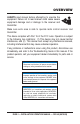
OVERVIEW ALWAYS read manual before attempting to operate the equipment. Failure not to read manual could cause severe equipment damage and or damage to the receiver and transmitter. Make sure work area is safe to operate radio control receiver and transmitter. This device complies with Part 15 of the FCC rules.
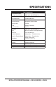
SPECIFICATIONS Table 1. Specifications Miratron Model Number: RX4 Radio Control Receiver General: CMD16-0135 ~ (MQ P/N EM98215) Power Requirements Radio: 12-24VDC, 500mA max Frequency Standard 902-928 MHz, FHSS, ISM Band Frequecy Control Direct FM FCC ID OUR9XCITE (Standard) Receiver Sensitivity -106 dBM Transmitter: Range CMD16-0135 ~ (MQ P/N EM98215) 300 ft. (91.44 meters) Line of Sight (Standard) Battery Type 1.5 Volt “AA” Alkaline (4) Battery Life (Standard) Standby, 80 hrs.
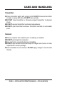
CARE AND HANDLING Transmitter: Clean transmitter gently with a damp cloth. DO NOT immerse transmitter in water, or spray with hose. DO NOT store outside. DO NOT drop transmitter or otherwise subject transmitter to physical shock. DO NOT expose transmitter to extreme temperatures. DO NOT open transmitter enclosure. Transmitter contains no serviceable parts. Receiver: Remove receiver from machine prior to welding on machine DO NOT paint electrical connector.
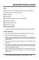
RECEIVER INSTALLATION Parts: Make sure all parts are accounted for before performing the installation. The following parts are included with the kit: Radio Transmitter Radio Receiver Spiral Antenna with associated mounting hardware Coaxial Antenna Cable Data /Power Cable (7-wire) Remote Control Cable Battery Disconnection 1. Disconnect the negative terminal of the battery cable from the battery. Ant enna Mounting 1. Drill a 3/4” hole into the hood on the C30HDG as shown in Figure 1. 2.
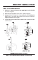
RECEIVER INSTALLATION Radio Control Receiver Mounting 1. Drill two 1/4” holes into the control box support panel on the C30HDG as shown in Figure 1. 2. After both holes have been drilled, deburr each hole opening. 3. Using a 1/4-20 x 1-1/4 bolt (2), 1/4 lock washer (2), 1/4 flat washer (2) and 1/4 nut (2), mount the radio control receiver onto the control box support panel as shown in Figure 1. 4. Connect BNC end of coaxial antenna cable to BNC connector on radio control receiver.
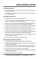
CABLE INSTALLATION Control Box Removal 1. Using a 7/16 socket remove the mounting bolts (3) that secure the control box to the support bracket. 2. Once the bolts have been removed, flip the panel downward to gain access to the connection points. Data Cable Connections 1. Wire data cable into control box as shown in Figure 2. 2. Crimp a 16-14 (3/16”) terminal ring onto the RED wire labeled BATT+. Connect this end of the wire to the +12VDC terminal strip, pin 2. 3.
WIRING DIAGRAM RED OR PINK 12-PIN DATA CABLE OL TR N CO IO ER AD EIV 4 R EC RX R MIR R AT SPLICE
TRANSMITTER/RECEIVER The definitions below describe the controls and functions of the Miratron Transmitter and Radio Control Receiver. Transmitter 1. Power On Switch — Place this switch in the ON position to turn on the transmitter. Be sure to place this switch in the OFF position when the system is not in use. 2. Status LED Indicator — Status LED blinks to indicate transmitter is ON and active. LED will double-blink when battery strength is low. 3.
TRANSMITTER/RECEIVER Functional Test Perform the functional test procedure below to test the remote control radio system.. 1. Start the engine as outlined on the operator’s manual. 2. Place the transmitter power ON/OFF switch in the ON position. 3. Place the pumping control switch on the control box in the REMOTE ON position. 4. Toggle the engine speed switch back and forth. Verify that engine speed increases and decreases. 5. Toggle pump ON/OFF switch. Verify that pumping starts and stops.
TROUBLESHOOTING Symptom Transmitter does not function at all Table 2. Troubleshooting Possible Problem LED status indicator not flashing. Solution Turn transmitter power switch ON. Weak dead battery, replace batteries. Check orientation of batteries. LED indicator not lit when power ON/OFF switch is pressed. Make sure transmitter has be matched (paired) to receiver. Receiver is not powered up.
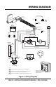
SYSTEM WIRING DIAGRAM Figure 4. System Wiring Diagram PAGE 14 — INSTALLATION OPERATION MANUAL — REV.
NOTE PAGE INSTALLATION/OPERATION MANUAL — REV.
INSTALLATION/OPERATION MANUAL HERE’S HOW TO GET HELP PLEASE HAVE THE MODEL AND SERIAL NUMBER ON-HAND WHEN CALLING UNITED STATES Multiquip Corporate Office 18910 Wilmington Ave. Carson, CA 90746 Contact: mq@multiquip.com MQ Parts Department Tel. (800) 421-1244 Fax (800) 537-3927 800-427-1244 310-537-3700 Fax: 800-672-7877 Fax: 310-637-3284 800-421-1244, Ext. 279 310-537-3700, Ext.