OPERATION AND PARTS MANUAL HDA-SERIES WALK-BEHIND TROWEL Revision #9 (07/02/10) To find the latest revision of this publication, visit our website at: www.multiquip.com THIS MANUAL MUST ACCOMPANY THE EQUIPMENT AT ALL TIMES.
PROPOSITION 65 WARNING Engine exhaust and some of its constituents, and some dust created by power sanding, sawing, grinding, drillingandotherconstructionactivities contains chemicals known to the State of California to cause cancer, birth defects and other reproductive harm. Some examples of these chemicals are: Leadfromlead-basedpaints. Crystallinesilicafrombricks. Cementandothermasonryproducts. Arsenicandchromiumfromchemically treatedlumber.
NOTES HDA-SERIES WALK-BEHIND TROWEL — OPERATION AND PARTS MANUAL — REV.
TABLE OF CONTENTS HDA-Series Walk-Behind Trowel Proposition 65 Warning ........................................... 2 Table Of Contents ................................................... 4 Parts Ordering Procedures ..................................... 5 Training Checklist .................................................... 6 Daily Pre-Operation Checklist ................................. 7 Safety Message Alert Symbols ............................ 8-9 Rules For Safe Operation .............................
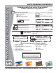
www.multiquip.com PARTS ORDERING PROCEDURES Ordering parts has never been easier! Choose from three easy options: Order via Internet (Dealers Only): Best Deal! Effective: January 1st, 2006 If you have an MQ Account, to obtain a Username and Password, E-mail us at: parts@multiquip. com. Order parts on-line using Multiquip’s SmartEquip website! N View Parts Diagrams N Order Parts N Print Specification Information To obtain an MQ Account, contact your District Sales Manager for more information.
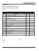
TRAINING CHECKLIST TRAINING CHECKLIST This checklist will lists some of the minimum requirements for machine maintenance and operation. Please feel free to detach it and make copies. Use this checklist whenever a new operator is to be trained or it can be used as a review for more experienced operator’s. TRAINING CHECKLIST NO. DESCRIPTION 1 Read Operator’s Manual completely. 2 Machine layout, location of components, checking of engine and gearbox fluid level. 3 Fuel system, refueling procedure.
DAILY PRE-OPERATION CHECKLIST DAILY PRE-OPERATION CHECKLIST DAILY PRE-OPERATION CHECKLIST 1 Engine Oil Level. 2 Gearbox Fluid Level. 3 Condition of Blades. 4 Blade Pitch Operation. 5 Safety Stop Switch Operation. 6 V-Belt Clutch Operation. COMMENTS: HDA-SERIES WALK-BEHIND TROWEL — OPERATION AND PARTS MANUAL — REV.
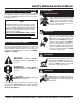
SAFETY MESSAGE ALERT SYMBOLS FOR YOUR SAFETY AND THE SAFETY OF OTHERS! Safety precautions should be followed at all times when operating this equipment. Failure to read and understand the Safety Messages and Operating Instructions could result in injury to yourself and others. NOTE This Owner's Manual has been developed to provide complete instructions for the safe and efficient operation of the MultiQuip HDA-SERIES WALK-BEHIND TROWEL.
SAFETY MESSAGE ALERT SYMBOLS Accidental Starting ALWAYS place the engine ON/OFF switch in the OFF position, when the trowel is not in use. Over Speed Conditions NEVER tamper with the factory settings of the engine governor or settings. Personal injury and damage to the engine or equipment can result if operating in speed ranges above maximum allowable. Respiratory Hazard ALWAYS wear approved respiratory protection. Sight and Hearing hazard ALWAYS wear approved eye and hearing protection.
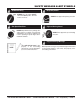
RULES FOR SAFE OPERATION RULES FOR SAFE OPERATION CAUTION: Failure to follow instructions in this manual may lead to serious injury or even death! This equipment is to be operated by trained and qualified personnel only! This equipment is for industrial use only. The following safety guidelines should always be used when operating the HDA-SERIES walk-behind trowel. SAFETY ■ DO NOT operate or service this equipment before reading this entire manual.
RULES FOR SAFE OPERATION ■ DO NOT operate this trowel unless all guards and safety devices are attached and in place. See pages 16 and 17. ■ ALWAYS use proper lifting techniques when moving the trowel. See page 24. ■ ALWAYS check to make sure that the operating area is clear before starting the engine. ■ ALWAYS test the safety stop switch devices before operating the trowel. ■ NEVER place your feet or hands inside the guard rings while starting or operating this equipment.
OPERATION AND SAFETY DECALS OPERATION AND SAFETY DECALS The HDA-SERIES walk-behind trowel is equipped with a number of operation and safety decals. These decals are provided for operator safety and maintenance information. Should any of these decals become unreadable, replacements can be obtained from your dealer. Figure 1. HDA-SERIES trowel Decals PAGE 12 — HDA-SERIES WALK-BEHIND TROWEL— OPERATION AND PARTS MANUAL — REV.
SPECIFICATIONS (TROWEL) SPECIFICATIONS (TROWEL) Top View Side View Figure 2. HDA-SERIES Trowel Dimensions Table 1. HDA-Series Trowel Specifications A– Height (Lifting Hook) 34.5 in (876.2 mm) B– Height Engagement Lever) 41.1 in (1,044.2 mm) 48.0 (1,168.4 mm) C–Width 75.2 (1,910.1 mm) D–Length Weight – Operating 230 lbs./105 Kg. Sound Pressure 97 db Vibration 2.5g (24.5 m/s2) Ring Diameter 46 in (117 cm) Number of Blades 4 Blade Tip Speed – FPM (m/s) 1,478 fpm (7.
SPECIFICATIONS (ENGINES) SPECIFICATIONS (ENGINES) Table 2. Specifications (Engine) Engine Model HONDA GX340K1QA2 HONDA GX390K1QA2 Type Air-cooled 4 stroke, Single Cylinder, OHV, Horizontal Shaft Gasoline Engine Air-cooled 4 stroke, Single Cylinder, OHV, Horizontal Shaft Gasoline Engine Bore X Stroke 3.2 in. X 2.5 in. (82 mm x 64 mm) 3.5 in. X 2.5 in. (88 mm x 64 mm) Displacement 20.6 cu. in. 337 cc 23.7 cu. in. 389 cc 11.0 H.P./3600 R.P.M. 13.0 H.P./3600 R.P.M. Approx. 1.72 U.S. Gallons (6.
GENERAL INFORMATION GENERAL INFORMATION HDA-SERIES Walk-Behind Trowel Familiarization This walk-behind trowel is designed for the floating and finishing of concrete slabs. Take a walk around the trowel. Take notice of all the major components (see pages 16 and 17) like the engine, blades, quick pitch control, air cleaner, centrifugal stop switch etc. Check that there is always oil in the engine. Blades The blades of the trowel finish the concrete as they are rotated around the surface.
CONTROLS AND COMPONENTS Figure 3. HDA-SERIES Walk-Behind Trowels PAGE 16 — HDA-SERIES WALK-BEHIND TROWEL— OPERATION AND PARTS MANUAL — REV.
CONTROLS AND COMPONENTS Figure 3 shows the location of the basic controls or components, for the HDA-SERIES trowel. Listed below is a brief explanation of each control or component 1. Quick-Pitch™ Control Handle – To adjust the pitch of the blades, grasp the handle then squeeze and either move the handle forward or backward to achieve the desired blade pitch. 2.
BASIC ENGINE BASIC ENGINE Figure 4. Engine Controls and Components INITIAL SERVICING The engine (Figure 4) must be checked for proper lubrication and filled with fuel prior to operation. Refer to the manufacturers engine manual for instructions & details of operation and servicing. 6. Choke Lever – Used in the starting of a cold engine, or in cold weather conditions. The choke enriches the fuel mixture. 1. 7. Air Cleaner – Prevents dirt and other debris from entering the fuel system.
ASSEMBLY AND INSTALLATION ASSEMBLY AND INSTALLATION Before the trowel can be put into operation there are some components that must be installed before the trowel can be used. This section provided general instructions on how to install those components. Instruction sheet P/N 20485 provides further details for the handle assembly. Handle Tube Installation (All Models) 1. Install the handle tube to the gearbox as shown in (Figure 5). The mounting hardware should be contained in the shipping container.
ASSEMBLY AND INSTALLATION 4. Tighten cable clamp screw and swivel stop screw. 5. After the cable has been installed on the engine, adjust and tighten operator position of the handle to lock the throttle cable at the proper length. 6. Adjust cable tension loosening the lock nut on the throttle cable receiver (Figure 9), loosening or tightening the adjuster nut below it, then retightening the lock nut. Figure 9. Throttle Adjust 7.
ASSEMBLY AND INSTALLATION 2. 3. 4. Lock the spring in the compressed position, by releasing the blade pitch adjustment trigger, (Quick-Pitch™ model). Remove one brass set nut from the blade pitch cable end as shown in (Figure 13). Pre-load Adjustment (Quick-Pitch™ Models Only) 1. After the Quick-Pitch™ handle has been installed on the trowel, spring pre-load adjustment will be required. 2. Locate the adjustment screw on the underside of the handle tube (Figure 15).
PRE-INSPECTION PRE-INSPECTION CAUTION NEVER operate the trowel in a confined area or enclosed area structure that does not provide ample free flow of air. ALWAYS wear approved eye and hearing protection before operating the trowel. NEVER place hands or feet inside the guard rings while the engine is running. ALWAYS shut the engine down before performing any kind of maintenance service on the trowel. It is recommended that the trowel's safety stop switch be used to stop the engine after every use.
PRE-INSPECTION Blade Check Explosive Fuel Fuel Check Motor fuels are highly flammable and can be dangerous if mishandled. DO NOT smoke while refueling. DO NOT attempt to refuel the trowel if the engine is hot! or running. 1. Remove the gasoline cap located on top of fuel tank. 2. Visually inspect to see if fuel level is low. If fuel is low, replenish with unleaded fuel. Check for worn or damaged blades. Check to see if one blade is worn out while the others look new.
INITIAL START-UP INITIAL START-UP DO NOT use your trowel until this section has been read and is thoroughly understood. CAUTION The trowel is heavy and awkward to move around. Use proper heavy lifting procedures and DO NOT lift the trowel by the guard rings. Lifting the Trowel Onto a Slab Auxiliary Lifting Tube Remove the auxiliary lifting tube located on top of the main handle. Insert the tube into the socket located on the opposite side of the gearbox (Figure 20) from the handle.
INITIAL START-UP 3. Place the centrifugal safety stop switch (Figure 23) in the "ON" position. 6. If the engine has started, slowly return the choke lever (Figure 24) to the OPEN position. If the engine has not started repeat steps 1 through 5. 7. Before the trowel is placed into operation, run the engine for several minutes. Check for fuel leaks, and noises that would associate with a loose guard ring and/or covers. 8. Test the Safety Stop Switch. a.
OPERATION OPERATION Maneuvering the Trowel The following steps are intended as a basic guide to machine operation, and are not to be considered a complete guide to concrete finishing. We suggest that all operators (experienced and novice) read “Slabs on Grade” published by the American Concrete Institute, Detroit, Michigan. Read the “Training” section of this manual for more information. 1. Get into the operator’s position behind the handle.
OPERATION (Figure 30) below illustrates a typical walk-behind trowel application. Practice maneuvering the trowel. The trick is to let the trowel do the work. Continue to practice maneuvering the trowel. Try to practice as if you were finishing a slab of concrete. Practice edging and covering a large area. Remember a good finishing technique is to work backwards. Be careful when moving backwards so that hazards can be avoided. The best way to get accustomed to the trowel is repeated use. Figure 30.
OPTIONS OPTIONS Clip-On Float Blades (Optional) Blades These blades will clip (Figure 33) on to an existing installed blade, allowing your finisher to float on “wet” concrete so that the troweling operation can begin as early as possible. They are easily removable, so that after the floating operation, when the concrete is sufficiently cured, they can be removed to expose the finish blades for continued troweling. Blades should be changed when they fail to finish concrete in a satisfactory manner.
OPTIONS Lifting Bail There is a heavy duty, center balance type lifting bail (Figure 35) made specifically for your trowel.These bales are ideal for lifting and transporting your trowel.They are designed to lift the finisher and balance it on it’s center of gravity, providing great stability while lifting.This option is not available on electric trowel models. A B Figure 35. Lifting Bail A. P/N 10157 (11 HP Engine) B.
MAINTENANCE MAINTENANCE Trowel Arm Adjustment Procedure See the engine manual supplied with your machine for appropriate engine maintenance schedule and troubleshooting guide for problems. NOTE At the front of the book (Page 7) there is a “Daily Pre-Operation Checklist ”. Make copies of this checklist and use it on a daily basis. CAUTION! ALWAYS allow the engine to cool before servicing. NEVER attempt any maintenance work on a hot! engine. MAINTENANCE SCHEDULE Daily (8-10 Hours) 1.
MAINTENANCE 2. Start engine, and bring trowel blades up to full speed and look for the following conditions: ■ Does the trowel have a perceived rolling or bouncing motion when in use? ■ Look at the trowel while it is running, does the guard ring “rock up and down” relative to the ground? Spider Removal 2. Loosen the jam nut and cone point square head set screw, and carefully lift the upper trowel assembly off of the spider assembly.
MAINTENANCE 3. Should the trowel arm inserts (bronze bushing ) come out with the trowel arm, remove the bushing from the trowel arm and set aside in a safe place. If the bushing is retained inside the spider plate, carefully remove the bushing. 4. Examine the bronze trowel arm bushing insert (Figure 42), clean if necessary. Replace bushing if out of round or worn. Trowel Arm Flatness Test 1.
MAINTENANCE Trowel Arm Adjustment Shown in (Figure 45) is the adjustment fixture with a trowel arm inserted. As each trowel arm is locked into the fixture, the arm bolt is adjusted to where it contacts a stop on the fixture. This will consistently adjust all of the trowel arms, keeping the finisher as flat and evenly pitched as possible. 1. Locate the trowel arm adjustment tool P/N 1817. Set the adjustment tool for a clockwise blade rotation, meaning the fixture arm is in the "UP" position. 3.
MAINTENANCE 11. Carefully lift the upper trowel assembly, line up the keyway on gear box main shaft and insert into spider assembly. 12. Reinstall square head cone point into spider plate and tighten in place. Tighten jam nut. Use care in making sure point of set screw engages groove in gear box main shaft. V-Belt Removal and Replacement 1. Remove the two T-Bolts and lock-washers that hold on the belt guard and remove the belt guard. 2. Work the belt up and over the bottom pulley and remove the belt. 13.
TROUBLESHOOTING (TROWEL) TABLE 4. TROUBLESHOOTING (TROWEL) SYMPTOM Engine running rough or not at all. Safety kill switch not functioning. If trowel “bounces, rolls concrete, or makes uneven swirls in concrete”. Machine has a perceptible rolling motion while running. POSSIBLE PROBLEM SOLUTION Kill switch malfunction? Make sure that the kill switch is ON or replace switch if necessary. Fuel? Look at the fuel system. Make sure there is fuel being supplied to the engine.
TROUBLESHOOTING (TROWEL) TABLE 4. TROUBLESHOOTING TROWEL (CONTINUED) SYMPTOM Clutch slipping or sluggish response to engine speed change. POSSIBLE PROBLEM SOLUTION Worn V-belts? Replace V-belt. Dir ty centrifugal clutch? Disassemble and clean clutch. Defective or worn out centrifugal clutch? Replace entire clutch. Hand clutch out of adjustment? Adjust per instructions in maintenance section of this manual. Worn or defective hand clutch par ts? Replace par ts as necessary.
TROUBLESHOOTING (ENGINE) TABLE 5. TROUBLESHOOTING (ENGINE) SYMPTOM Difficult to star t, "fuel is available, but no SPARK at spark plug". POSSIBLE CAUSE Spark plug bridging? Check gap, insulation or replace spark plug. Carbon deposit on spark plug? Clean or replace spark plug. Shor t circuit due to deficient spark plug insulation? Check spark plug insulation, replace if worn. Improper spark plug gap? Set to proper gap. ON/OFF switch is shor ted? Check switch wiring, replace switch.
EXPLANATION OF CODES The following section explains the different symbols and remarks used in the Parts section of this manual. Use the help numbers found on the back page of the manual if there are any questions. NOTICE The contents and part numbers listed in the parts section are subject to change without notice. Multiquip does not guarantee the availability of the parts listed. SAMPLE PARTS LIST NO. 1 2% 2% 3 4 PART NO. PART NAME QTY. REMARKS 12345 BOLT......................1 .....
SUGGESTED SPARE PARTS HDA-SERIES TROWEL 1 TO 3 UNITS WITH HONDA GX340K1QA2 AND GX390K1QA2 ENGINES. 1 to 3 Units Qty. ......P/N ........................... Description 1 ...........20478 ................ GRIP, LEFT 1 ...........20463 ................ GRIP, RIGHT 2 ...........20856 ................ SAFETY SWITCH 1 ...........20285 ................ CABLE STANDARD HANDLE 1 ...........20297 ................ CABLE QUICK-PITCH™ 1 ...........20435 ................ THROTTLE CABLE 4 ...........1157 A ...............
NAMEPLATE AND DECALS PAGE 40 — HDA-SERIES WALK-BEHIND TROWEL— OPERATION AND PARTS MANUAL — REV.
NAMEPLATE AND DECALS NO. 1 2 3 4 5 6 7 8 9 PART NO. 1758 12405 20527 20526 2942 1736 1735 11246 10 11 12 13 14 15 16 17 18 19 20 1940 11092 11246 1492 1147 11246 1261 1848 2938 11246 2423 NOTE PART NAME QTY. REMARKS 1 DECAL: QUICK-PITCH™ HANDLE DECAL: QUICK-PITCH™ HANDLE INSERT 2 1 DECAL: QUICK-PITCH™ WARNING DECAL: QUICK-PITCH™ LATCH WARNING 1 DECAL: MQ WHITEMAN 13" 1 DECAL: ARROWS 1 DECAL: PRE-LOAD INDICATOR 1 DECAL: OIL CHECK ............................................. 1 .......
STANDARD HANDLE ASSY. (OLD STYLE) 40 3 21 5 7 4 8 6 9 1 16 22 18 17 43 DETAIL “A” 42 14 2 12 15 19 2 1 11 3 SEE DETAIL “B” 21 22 20 30 44 SEE DETAIL “A” 24 13 41 28 1 23 27 31 26 25 32 37 39 28 1 38 36 10 35 35 29 33 2 DETAIL “B” 34 1 APPLY THREAD LOCK (LOCTITE 242 BLUE OR EQUIVALENT). 2 PART OF ENGINE ASSEMBLY. 3 COMPLETE HANDLE ASSY, P/N 20299 NO LONGER AVAILABLE. WHEN REPLACING ENTIRE ASSY, USE P/N 22258. SEE STANDARD HANDLE ASSY.
STANDARD HANDLE ASSY. (OLD STYLE) NO. 1 2 3 PART NO. 20478 20774 20818 4 * 5 * 6 * 7 * 8 * 9 * 10 11 12 13 14 15 16 17 18 19 20 21% 22 23 24 25# 26# 27# 28 29 30 31 32 33 34 35 36 37 38 39 40 41 42 43 44 20817 0281 20282 0122 C 3615 1478 21172 12556 21171 20439 1492 20438 0786 0786 A 20287 20285 20856 1602 20988 20514 1662 20460 1118 20279 0169 10136 12567 2942 21173 20845 1116 10133 20392 20461 20819 20299 20301 20421 A8638 PART NAME QTY. REMARKS GRIP, HANDLE 2 COVER, PAD HANDLE 1 DECAL, STD PITCH.....
STANDARD HANDLE ASSY. (NEW STYLE) 31 13 32 35 33 36 34 11 21 9 2 1 15 6 18 14 40 24 25 20 10 23 22 26 38 8 37 39 19 12 5 7 16 17 4 29 30 3 28 39 27 1 1 APPLY THREAD LOCK (LOCTITE 242 BLUE OR EQUIVALENT). PAGE 44 — HDA-SERIES WALK-BEHIND TROWEL— OPERATION AND PARTS MANUAL — REV.
STANDARD HANDLE ASSY. (NEW STYLE) NO. PART NO. 1% 0786 2% 0786A 3% 1116 4% 1284 5% 3233 6% 9154 7% 10133 8% 20285 9% 20287 10% 20439 11% 20478 12% 20514 13% 20819 14% 20856 15% 21171 16% 21172 17% 21173 18% 22055 19% 22059 20% 22095 21% 22166 22% 22167 23% 22206 24% 22256 25% 22263 26% 22226 27%@ 20461 28%@# 1118 29%@# 20460 30%@# 20279 31%$ 20817 32%$ 0281 33%$ 20282 34%$ 3615 35%$ 0122 C 36%$ 1478 37%@ 10133 38%@ 10136 39%@ 0169 40 22258 PART NAME QTY.
QUICK-PITCH™ HANDLE ASSY. (OLD STYLE) 2 1 25 55 6 5 1 18 20 19 26 21 14 58 4 10 7 24 25 17 8 9 57 10 ASM 15 11 54 DETAIL “A” 22 11 12 13 SEE DETAIL “A” 26 16 48 60 23 27 SEE DETAIL “B” 59 28 46 45 49 30 29 32 31 3 50 51 43 44 38 42 52 DETAIL “B” 41 47 2 34 33 1 38 40 39 37 36 35 56 33 1 53 1 APPLY THREAD LOCK (LOCTITE 242 BLUE OR EQUIVALENT). 2 PART OF ENGINE ASSEMBLY. 3 COMPLETE HANDLE ASSY, P/N 12645 NO LONGER AVAILABLE.
QUICK-PITCH™ HANDLE ASSY. (OLD STYLE) NO. 1 2 3 4 5 6 7 8 * 9 * 10 * 11 12 * 13 * 14 15 16 17 18 19+ 20+ 21+ 22+ 23+ 24 25 * 26 27 28 29 30 31 32 33 34 35# 36# 37# 38 39 40 PART NO. 20478 20774 10136 12556 20526 21171 20527 20389 1746 12405 1729 1706 20437 4568 1711 1719 20439 20438 1731 20443 1709 20269 20276 20856 1602 20988 20514 20297 2942 1715 20270 1735 0169 1662 20460 1118 20279 10133 1737 1733 PART NAME QTY.
QUICK-PITCH™ HANDLE ASSY. (OLD STYLE) 2 1 25 55 6 5 1 18 20 19 26 21 14 58 4 10 7 24 25 17 8 9 57 10 ASM 15 11 54 DETAIL “A” 22 11 12 13 SEE DETAIL “A” 26 16 48 60 23 27 SEE DETAIL “B” 59 28 46 45 49 30 29 32 31 3 50 51 43 44 38 42 52 DETAIL “B” 41 47 2 34 33 1 38 40 39 37 36 35 56 33 1 53 1 APPLY THREAD LOCK (LOCTITE 242 BLUE OR EQUIVALENT). 2 PART OF ENGINE ASSEMBLY. 3 COMPLETE HANDLE ASSY, P/N 12645 NO LONGER AVAILABLE.
QUICK-PITCH™ HANDLE ASSY. (OLD STYLE) NO. 41 42 43 44 45 46 47 48 49 50 51 52 53 54 55 56 57 58 59 60 PART NO. 1736 1718 1732 1717 12642 1758 20845 21173 20392 21172 1116 20390 20293 20461 12645 20421 A8638 20297 PART NAME QTY. REMARKS DECAL, ARROW 1 NUT, QP TRIM CONTROL ADJUST 1 BOLT, STRIPPER 3/8 X 1/2 1 SCREW, QP TRIM ADJUSTMENT 1 TUBE, MAIN HANDLE 1 DECAL, PATENT QP 1 SWIVEL, ENGINE THROTTLE CABLE 1 HOUSING, THROTTLE CABLE 74” 1 DECAL, CAUTION, LIFT HANDLE ......................... 1 .................
QUICK-PITCH™ HANDLE ASSY. (NEW STYLE) 17 41 38 36 37 6 39 7 32 40 16 42 43 44 45 29 12 46 19 22 25 26 54 2 3 33 21 4 13 31 18 27 51 20 50 15 30 34 11 14 35 5 8 24 52 9 1 28 23 10 47 48 49 53 50 PAGE 50 — HDA-SERIES WALK-BEHIND TROWEL— OPERATION AND PARTS MANUAL — REV.
QUICK-PITCH™ HANDLE ASSY. (NEW STYLE) NO. 1% 2% 3% 4% 5% 6%@ 7%@ 8% 9% 10% 11% 12%# 13% 14% 15% 16% 17% 18% 19% 20% 21% 22% 23% 24% 25% 26% 27% 28% 29% 30% 31% 32%@ 33% 34% 35% 36%@ 37%@ 38%@ 39%@ 40%@ 41%@ 42%# 43%# 44%# 45%# 46%# 47%$& 48%$& 49%$& 50%$& 51%$ 52%$ 53%$ 54 PART NO.
4-BLADE SPIDER ASSY. PAGE 52 — HDA-SERIES WALK-BEHIND TROWEL— OPERATION AND PARTS MANUAL — REV.
4-BLADE SPIDER ASSY. NO. 1 * 2 * 3 * 4 * 5% 6% 7% 8% 9% 10% 11% 12% 13% 14% 15% 16% 17% 18% 19% 20% 21 22 # * 23 PART NO. 12208 12778 10816 9009 11039 0164 B 1875 1876 0105 0161 C 1162 A 2829 9005 4164 9111 11778 1322 1456 1167 A 0166 A 9150 1471 10969 PART NAME QTY. REMARKS WEAR RING 1 FLANGE BEARING 1 THRUST COLLAR ............................................................. 1 ........... INCLUDES ITEMS W/# WEAR PLATE 1 BUSHING 4 RADIUS HEAD 3/8- 16 x 1-1/4” 4 INT. SHKP.
GEARBOX & ENGINE MOUNTS ASSY. PAGE 54 — HDA-SERIES WALK-BEHIND TROWEL— OPERATION AND PARTS MANUAL — REV.
GEARBOX & ENGINE MOUNTS ASSY. NO. 1% * 2% 3% 4% * 5% * 6%# 7%# 8% 9% 10% 11% 12 13% 14% 15% 16% 16% 17% 18%# 19%# 20% 21% 22% 23 24% * 25% * 26% 27% 28% 29% * 30 31 32 33 34 35 36 37 38 39 39 40 41 42 PART NO. 12909 2295 9047 2309 12583 232 A 9045 1580 12908 20540 1132 9048 9046 10031 0121 A 12944 12943 1138 1139 232 9181 9179 9180 1238 9037 9038 9036 0400 B 20875 9041 9027 10136 0683 9028 7299 1245 1951 11541 1247 20879 20882 2618 2619 10139 PART NAME QTY.
ENGINE, 11 HP HONDA ASSY. PAGE 56 — HDA-SERIES WALK-BEHIND TROWEL— OPERATION AND PARTS MANUAL — REV.
ENGINE, 11 HP HONDA ASSY. NO. 1 2 3 4 5 6 7 8 9 10 11 12 13 14 15 16 17 18 19 20 21 22 23 24 25 26 27 PART NO. 1388 1391 0161 C 0300 B 0310 2480 1488 1475 0261 2362 9119 10222 10136 2724 9154 0166 A 20982 1480 1951 1245 1247 9123 9120 0478 2361 1313 PART NAME QTY. REMARKS ENGINE 11 HP HONDA 1 HHCS 5/16-24 x 1-1/2" 4 LOCK WASHER 5/16" 4 FLAT WASHER 5/16" 4 SQUARE KEY 1/4X1/4X1.1/2" 1 CLUTCH, 4" P-G 35 DEGREE 1" 1 WIRE, SAFETY SWITCH 1 CONNECTOR, SPLICE TAP 1 BELT, A31 GATES HPII ONLY 2 SPACER, 1-1/4 X .
ENGINE, 13 HP HONDA ASSY. PAGE 58 — HDA-SERIES WALK-BEHIND TROWEL— OPERATION AND PARTS MANUAL — REV.
ENGINE, 13 HP HONDA ASSY. NO. 1 2 3 4 5 6% 7 8 9 10 11 12 13 14 15 16 17 18 19 20# 21 22 23 24 25 26 27 28 PART NO. 3364 1391 0161 C 0300 B 11535 1304 1488 1475 11536 1848 11537 11440 0948 0131 A 1245 1247 20982 1480 11541 1580 11543 11560 9123 0166 A 12921 11154 1672 PART NAME QTY. REMARKS ENGINE 13HP HONDA 1 HHCS 5/16-24 x 1-1/2" 4 LOCK WASHER 5/16" 4 FLAT WASHER 5/16" 4 CLUTCH, COMET 302353C ........................... 1 ...........
GUARD RING ASSY. PAGE 60 — HDA-SERIES WALK-BEHIND TROWEL— OPERATION AND PARTS MANUAL — REV.
GUARD RING ASSY. NO. 1 PART NO. 9178 PART NAME GUARD RING ASSEMBLY QTY. 1 REMARKS HDA-SERIES WALK-BEHIND TROWEL — OPERATION AND PARTS MANUAL — REV.
STABILIZER RING ASSY. 5 SEE DETAIL “A” 4 DETAIL “A” 1 4 3 1 1 2 1 APPLY LOCTITE 242 BLUE OR EQUIVALENT. PAGE 62 — HDA-SERIES WALK-BEHIND TROWEL— OPERATION AND PARTS MANUAL — REV.
STABILIZER RING ASSY. NO 1 2 3 4 5 PART NO 0161 C 1237 1723 6014 C 7311 PART NAME WASHER, LOCK, 5/16 MED SCREW, SCH 5/16-18 X 7/8, NYL, NP ROD END, 5/16-24 MALE NUT, HEX FINISH 5/16-24 RING, STABILIZER, HD-4 QTY. 8 4 4 8 1 REMARKS HDA-SERIES WALK-BEHIND TROWEL — OPERATION AND PARTS MANUAL — REV.
BLADES & ARM ADJ. FIXTURE ASSY. (OPTIONS) PAGE 64 — HDA-SERIES WALK-BEHIND TROWEL— OPERATION AND PARTS MANUAL — REV.
BLADES & ARM ADJ. FIXTURE ASSY. (OPTIONS) NO. 20 20 21 22 22 23 24 26 27 28 29 30 39 39 40 40 41 42 44 46 47 48 49 50 PART NO. 0202 0201 1434 1162 A 7281 6014 C 1237 0166 A 1723 PART NAME QTY. REMARKS COMBO FLOAT & FINISH BLADE ................. 4 ........ CONTACT UNIT SALES DEPT./ACC. ITEM ENDURO COMBO FLOAT &FINISH BLADE . 4 ........ CONTACT UNIT SALES DEPT./ACC. ITEM FLOAT BLADE ............................................... 4 ........ CONTACT UNIT SALES DEPT./ACC. ITEM FINISH BLADE ...............
LIFTING BAIL ASSY. (OPTION) PAGE 66 — HDA-SERIES WALK-BEHIND TROWEL— OPERATION AND PARTS MANUAL — REV.
LIFTING BAIL ASSY. (OPTION) NO. 1 2 3 4 5 PART NO. 10229 0161 A 2360 PART NAME QTY. REMARKS LIFTING BAIL ASSY. (13 HP MODEL) . 1 ............ CONTACT UNIT SALES DEPT./ACC. ITEM HHCS 5/16-24X1" 4 LOCK WASHER 5/16" 4 LIFTING BAIL ASSY. (11 HP MODEL) . 1 ............ CONTACT UNIT SALES DEPT. /ACC. ITEM RUNNER, BELT (11 HP MODEL) 1 HDA-SERIES WALK-BEHIND TROWEL — OPERATION AND PARTS MANUAL — REV.
HONDA GX340K1QA2 — AIR CLEANER ASSY. PAGE 68 — HDA-SERIES WALK-BEHIND TROWEL— OPERATION AND PARTS MANUAL — REV.
HONDA GX340K1QA2 — AIR CLEANER ASSY. NO. 1 2 3 4 5 6 7 * 8 * 9 11 12 13 14 PART NO. 16271ZE2000 17210ZE3505 17218ZE3505 17231ZE3W00 17232891000 17235ZH9N00 17238ZE2310 17239ZE1000 17410ZH9N00 90203ZA0800 90325044000 934040602008 9405006000 PART NAME QTY. REMARKS GASKET, ELBOW 1 ELEMENT, AIR CLEANER 1 FILTER, OUTER 1 COVER, AIR CLEANER 1 GROMMET, AIR CLEANER 1 NOSE, MUFFLER 1 COLLAR, AIR CLEANER 2 COLLAR B, AIR CLEANER 1 ELBOW, AIR CLEANER ............................... 1 ...........
HONDA GX340K1QA2 — CAMSHAFT ASSY. PAGE 70 — HDA-SERIES WALK-BEHIND TROWEL— OPERATION AND PARTS MANUAL — REV.
HONDA GX340K1QA2 — CAMSHAFT ASSY. NO. 1 2 3 4 5 6 * 7 8 9 10 11 12 13 14 15 16 17 PART NO. 14100ZE3305 14410ZE3013 14431ZE2010 14441ZE2000 14451ZE1013 14568ZE1000 14711ZE3000 14721ZE3000 14751ZE2003 14771ZE2000 14773ZE2000 14775ZE2010 14781ZE2000 14791ZE2010 90012ZE0010 90206ZE1000 12209ZE8003 PART NAME QTY. REMARKS CAMSHAFT ASSEMBLY ............................. 1 ........... INCLUDES ITEMS W/ * ROD, PUSH 2 ARM, VALVE ROCKER 2 LIFTER, VALVE 2 PIVOT, ROCKER ARM 2 SPRING, WEIGHT RETURN 1 VALVE, IN.
HONDA GX340K1QA2 — PISTON ASSY. PAGE 72 — HDA-SERIES WALK-BEHIND TROWEL— OPERATION AND PARTS MANUAL — REV.
HONDA GX340K1QA2 — PISTON ASSY. NO. 1 1 1 1 2 2 2 2 3 4 4 5 * 6 PART NO. 13010ZE3003 13011ZE3003 13012ZE3003 13013ZE3003 13101ZE3W00 13102ZE3W00 13103ZE3W00 13104ZE3W00 13111ZF6000 13200ZE3010 13200ZE3315 90001ZE8000 90601ZE3000 PART NAME QTY. REMARKS RING SET, PISTON- STANDARD 1 RING SET, PISTON- OS 0.25 1 RING SET, PISTON- OS 0.50 1 RING SET, PPISTON- 0.75 1 PISTON- STANDARD 1 PISTON- OS 0.25 1 PISTON- OS 0.50 1 PISTON- 0.75 1 PIN, PISTON 1 ROD ASSEMBLY, CONNECTING (STD.) ..................... 1 .......
HONDA GX340K1QA2 — CRANKCASE COVER ASSY. PAGE 74 — HDA-SERIES WALK-BEHIND TROWEL— OPERATION AND PARTS MANUAL — REV.
HONDA GX340K1QA2 — CRANKCASE COVER ASSY. NO. 1+ 2 3 4 5 7$ 8■ 9+ 10 +% * 11 +% * 12 +% * 13 + * 15 + * 16 17+ 18 + * 19 20+ 21+ PART NO. 06165ZE3000 11300ZE3602 11381ZE3801 15600ZG4003 15600735003 15625ZE1003 15625ZE1003 16510ZE3000 16511ZE8000 16512ZE3000 16513ZE2000 16531ZE2000 90602ZE1000 90701HC4000 91201ZE3004 9410106800 957010804000 961006202000 961006207000 PART NAME QTY. REMARKS GOVERNOR KIT, ............................................... 1 ...........
HONDA GX340K1QA2 — CRANKSHAFT ASSY. PAGE 76 — HDA-SERIES WALK-BEHIND TROWEL— OPERATION AND PARTS MANUAL — REV.
HONDA GX340K1QA2 — CRANKSHAFT ASSY. NO. 1 5 6 7 PART NO. 13310ZE3601 13351ZE3010 90756ZE2600 961006207000 PART NAME QTY. REMARKS CRANKSHAFT Q- TYPE ............................. 1 .....................INCLUDES ITEMS W/ * WEIGHT, BALANCER 1 KEY 6.3X6.3X43 1 BEARING, RADIAL BALL 6207 1 HDA-SERIES WALK-BEHIND TROWEL — OPERATION AND PARTS MANUAL — REV.
HONDA GX340K1QA2 — CYLINDER BARREL ASSY. PAGE 78 — HDA-SERIES WALK-BEHIND TROWEL— OPERATION AND PARTS MANUAL — REV.
HONDA GX340K1QA2 — CYLINDER BARREL ASSY. NO. 1 2 PART NO. 12000ZE3816 15510ZE2043 3 4 5 6 7 9 * 10 * 11 12 13 14 15 16 * 17 18 16541ZE3010 32197ZE2003 90013883000 90131896650 90446KE1000 91201ZE3004 91201ZE9003 91353671003 9405010000 9410912000 9425110000 957010601200 961006202000 90013883000 34150ZH7003 PART NAME QTY. REMARKS CYLINDER ASSEMBLY ............................... 1 ........... INCLUDES ITEMS W/ * SWITCH ASSEMBLY, OIL LEVEL ............... 1 ...........
HONDA GX340K1QA2 — CYLINDER HEAD ASSY. PAGE 80 — HDA-SERIES WALK-BEHIND TROWEL— OPERATION AND PARTS MANUAL — REV.
HONDA GX340K1QA2 — CYLINDER HEAD ASSY. NO. 1 2 * 3 * 4 * 5 6 7 8 10 11 12 12 13 14 15 16 PART NO. 12200ZF6W01 12204ZE2306 12205ZE2305 12216ZE2300 12251ZE3W00 12310ZE3791 12315ZE3840 12391ZE2020 90014ZE2000 90042ZE8000 90047ZE2000 92900080320E 90441ZE2010 9430112200 957011008000 9807956846 PART NAME QTY. REMARKS CYLINDER HEAD ......................................... 1 ........... INCLUDES ITEMS W/ * GUIDE, EX. VALVE OS (OPTIONAL) 1 GUIDE, EX.
HONDA GX340K1QA2 — FAN COVER ASSY. PAGE 82 — HDA-SERIES WALK-BEHIND TROWEL— OPERATION AND PARTS MANUAL — REV.
HONDA GX340K1QA2 — FAN COVER ASSY. NO. 1 2 3 4 5 5 7 8 PART NO. 16731ZE2003 19610ZE3010ZA 19631ZE3W00 32197ZH8003 36100ZE1015 36100ZH7003 90013883000 90684ZA0601 PART NAME QTY. REMARKS CLIP, TUBE 1 COVER, FAN *R8* (BRIGHT RED) 1 SHROUD 1 SUB- HARNESS .......................................... 1 ........... USE UP TO ENGINE SN 2639737 SWITCH ASSEMBLY, ENGINE STOP ......... 1 ........... USE UP TO ENGINE SN 2639737 SWITCH ASSEMBLY, ENGINE STOP ......... 1 ...........
HONDA GX340K1QA2 — FLYWHEEL ASSY. PAGE 84 — HDA-SERIES WALK-BEHIND TROWEL— OPERATION AND PARTS MANUAL — REV.
HONDA GX340K1QA2 — FLYWHEEL ASSY. NO. 1 2 4 6 6 7 PART NO. 19511ZE3000 28450ZE3W11 31100ZE3701 90201ZE3V00 90201ZE3790 90741ZE2000 PART NAME QTY. REMARKS FAN, COOLING 1 PULLEY, STARTER (SCREEN GRID) 1 FLYWHEEL 1 NUT, SPECIAL 16MM (1) ............................. 1 ........... USE FROM ENGINE SN 2536523 NUT, SPECIAL 16MM .................................. 1 ........... USE UP TO ENGINE SN 2536522 KEY, SPECIAL WOODRUFF 25X18 1 HDA-SERIES WALK-BEHIND TROWEL — OPERATION AND PARTS MANUAL — REV.
HONDA GX340K1QA2 — FUEL TANK ASSY. PAGE 86 — HDA-SERIES WALK-BEHIND TROWEL— OPERATION AND PARTS MANUAL — REV.
HONDA GX340K1QA2 — FUEL TANK ASSY. NO. 1 2 3 3 5 6 * 7 10 11 12 13 14 PART NO. 16854ZH8000 16955ZE1000 17510ZE3010ZA 17510ZE3010ZD 17620ZH7023 17631ZH7003 17672ZE2W01 91353671003 9405008000 950014500360M 9500202080 957010802500 PART NAME QTY. REMARKS RUBBER, SUPPORTER 107MM 1 JOINT, FUEL TANK 1 TANK, FUEL *NH31* (MCKINLEY WHITE) 1 TANK FUEL *T34* (SIMPSON BLUE) 1 CAP, FUEL FILLER ............................................1 ............
HONDA GX340K1QA2 — IGNITION COIL ASSY. PAGE 88 — HDA-SERIES WALK-BEHIND TROWEL— OPERATION AND PARTS MANUAL — REV.
HONDA GX340K1QA2 — IGNITION COIL ASSY. NO. 1 2 4 7 10 PART NO. 30500ZE2023 30700ZE1013 31512ZE2000 36101ZE2701 90015883000 PART NAME COIL ASSEMBLY, IGNITION CAP ASSEMBLY, NOISE SUPPRESSOR GROMMET, WIRE WIRE, STOP SWITCH 430MM BOLT, FLANGE 6X28 QTY. 1 1 1 1 2 REMARKS HDA-SERIES WALK-BEHIND TROWEL — OPERATION AND PARTS MANUAL — REV.
HONDA GX340K1QA2 — CARBURETOR ASSY. PAGE 90 — HDA-SERIES WALK-BEHIND TROWEL— OPERATION AND PARTS MANUAL — REV.
HONDA GX340K1QA2 — CARBURETOR ASSY. NO. 1 % * 2 * 3 * 4 * 4 * 5 * 6 % * 7 * 8 * 9 9 9 10 * 11 * 12 * 13 14 15 16 17 18 19 20 21 * 22 * 23 * 24 * 25+ 26 26 26 27 PART NO.
HONDA GX340K1QA2 — CARBURETOR ASSY. PAGE 92 — HDA-SERIES WALK-BEHIND TROWEL— OPERATION AND PARTS MANUAL — REV.
HONDA GX340K1QA2 — CARBURETOR ASSY. NO. 21 * 22 * 23 * 24 * 25+ 26 26 26 27 PART NO. 16956ZE1811 16957ZE1812 16967ZE0811 93500030060H 9430520122 99101ZH80880 99101ZH80900 99101ZH80920 99204ZE00350 PART NAME QTY. REMARKS SPRING, VALVE LEVER 1 GASKET, VALVE 1 CUP, FUEL STRAINER 1 SCREW, PAN (3X6) ................................... 2 .........
HONDA GX340K1QA2 — MUFFLER ASSY. PAGE 94 — HDA-SERIES WALK-BEHIND TROWEL— OPERATION AND PARTS MANUAL — REV.
HONDA GX340K1QA2 — MUFFLER ASSY. NO. 1 2 3 4 5 6 6 8 9 11 12 13 14 15 PART NO. 18310ZE3W00 18320ZE3W01 18323ZE3W40 18330ZE2W00 18331ZE3810 18333ZF6W01 18333ZK6Y00 18355ZE3010 18381ZE2W10 90013883000 90050ZE1000 90055ZE1000 93500060060B 9405008000 PART NAME MUFFLER PROTECTOR, MUFFLER PROTECTOR, EX. PIPE PIPE, EX. CAP, MUFFLER GASKET, EX. PIPE GASKET, EX.
HONDA GX340K1QA2 — RECOIL STARTER ASSY. PAGE 96 — HDA-SERIES WALK-BEHIND TROWEL— OPERATION AND PARTS MANUAL — REV.
HONDA GX340K1QA2 — RECOIL STARTER ASSY. NO. 1 2 * 3 * 4 * 5 * 6 * 7 * 8 * 9 * 10 * 11 * 12 * 13 * 14 PART NO. 28400ZEW01ZA 28410ZE3W01ZA 28421ZE3W01 28422ZE2W01 28441ZE2W01 28442ZE2W01 28443ZE2W01 28444ZE2W01 28445ZE2W01 28461ZE2W02 28462ZE3W01 28469ZE2W01 90004ZE2W01 957010600800 PART NAME QTY. REMARKS STARTER ASSY., RECOIL *R8* BGHT RED ........... 1 ......
HONDA GX340K1QA2 — CONTROL ASSY. NO ART WORK PAGE 98 — HDA-SERIES WALK-BEHIND TROWEL— OPERATION AND PARTS MANUAL — REV.
HONDA GX340K1QA2 — CONTROL ASSY. NO. 2 3 4 5 7 8 9 10 11 12 14 15 17 18 19 22 23 24 PART NO.
HONDA GX340K1QA2 — LABELS ASSY. PAGE 100 — HDA-SERIES WALK-BEHIND TROWEL— OPERATION AND PARTS MANUAL — REV.
HONDA GX340K1QA2 — LABELS ASSY. NO. 1 3 4 6 9 PART NO. 87521ZE3W01 87522ZH9000 87528ZE2810 87532ZH8810 89218ZE1000 PART NAME EMBLEM LABEL, CAUTION MARK, CHOKE (EXTERNAL) MARK, OIL ALERT (E) WRENCH, SPARK PLUG QTY. 1 1 1 1 1 REMARKS HDA-SERIES WALK-BEHIND TROWEL — OPERATION AND PARTS MANUAL — REV.
HONDA GX390K1QA2— AIR CLEANER ASSY. PAGE 102 — HDA-SERIES WALK-BEHIND TROWEL— OPERATION AND PARTS MANUAL — REV.
HONDA GX390K1QA2— AIR CLEANER ASSY. NO. 1 2 3# 4 4 5# 7 * 8 * 9 11 12 13 14 PART NO. 16271ZE2000 17210ZE3505 17218ZE3505 17231ZE3W00 17231ZE3W01 17232891000 17238ZE2310 17239ZE1000 17410ZH9N00 90203ZA0800 90325044000 90009ZE2003 9405006000 PART NAME QTY. REMARKS GASKET, ELBOW 1 ELEMENT, AIR CLEANER .......................... 1 ......... INCLUDES ITEMS W/# FILTER, OUTER 1 COVER, AIR CLEANER .............................. 1 .........
HONDA GX390K1QA2— CAMSHAFT ASSY. PAGE 104 — HDA-SERIES WALK-BEHIND TROWEL— OPERATION AND PARTS MANUAL — REV.
HONDA GX390K1QA2— CAMSHAFT ASSY. NO. 1 PART NO. 14100ZF6W01 1 14100ZF6305 2 3 3 4 5 6 * 7 8 9 10 11 12 13 14 15 16 17 14410ZE3013 14431ZE2000 14431ZE2010 14441ZE2000 14451ZE1013 14568ZE1000 14711ZE3000 14721ZE3000 14751ZE2003 14771ZE2000 14773ZE2000 14775ZE2010 14781ZE2000 14791ZE2010 90012ZE0010 90206ZE1000 12209ZE8003 PART NAME QTY. REMARKS CAMSHAFT ASSEMBLY ................................. 1 ......... INCLUDES ITEMS W/ * .............................................................................
HONDA GX390K1QA2— PISTON ASSY. PAGE 106 — HDA-SERIES WALK-BEHIND TROWEL— OPERATION AND PARTS MANUAL — REV.
HONDA GX390K1QA2— PISTON ASSY. NO. 1 1 1 1 1 2 2 2 2 3 4 PART NO. 13010ZF6003 13011ZF6003 13012ZF6003 13012ZF6005 13013ZF6003 13101ZF6W00 13102ZF6W00 13103ZF6W00 13104ZF6W00 13111ZF6W00 13200ZE3010 4 13200ZE3020 4 5 * 6 13200ZE3315 90001ZE8000 90601ZE3000 PART NAME QTY. REMARKS RING SET, PISTON (STD.) 1 RING SET, PISTON (OS 0.25), OPT. 1 RING SET, PISTON (OS 0.50), OPT. 1 RING SET, PISTON (OS 0.50), OPT. 1 RING SET, PISTON (0.75) NIPPON, OPT. 1 PISTON (STANDARD) 1 PISTON (OS 0.
HONDA GX390K1QA2— CRANKCASE COVER ASSY. PAGE 108 — HDA-SERIES WALK-BEHIND TROWEL— OPERATION AND PARTS MANUAL — REV.
HONDA GX390K1QA2— CRANKCASE COVER ASSY. NO. 1 * 2 3 4 5 8% 9 # * 10 #+ * 11 #+ * 12 #+ * 13 #+ * 15 # * 16 17 * 18 # * 19 20 * 21 * PART NO. 06165ZE3000 11300ZE3602 11381ZE3801 15600ZG4003 15600735003 15625ZE1003 16510ZE3000 16511ZE8000 16512ZE3000 16513ZE2000 16531ZE2000 90602ZE1000 90701HC4000 91201ZE3004 9410106800 957010804000 961006202000 961006207000 PART NAME QTY. REMARKS GOVERNOR KIT (OPIONAL) ........................... 1 ......... INCLUDES ITEMS W/# COVER ASSY., CRANKCASE (Q TYPE) ........ 1 ..
HONDA GX390K1QA2— CRANKSHAFT ASSY. PAGE 110 — HDA-SERIES WALK-BEHIND TROWEL— OPERATION AND PARTS MANUAL — REV.
HONDA GX390K1QA2— CRANKSHAFT ASSY. NO. 2 6 9 10 * PART NO. 13310ZF6W10 13351ZE3010 90745ZE2600 91001ZF6003 PART NAME QTY. REMARKS CRANKSHAFT, Q-TYPE .................................. 1 ......... INCLUDES ITEMS W/ * WEIGHT, BALANCER 1 KEY 6.3X6.3X43 1 BEARING, RADIAL BALL 6207S 1 HDA-SERIES WALK-BEHIND TROWEL — OPERATION AND PARTS MANUAL — REV.
HONDA GX390K1QA2— CYLINDER BARREL ASSY. PAGE 112 — HDA-SERIES WALK-BEHIND TROWEL— OPERATION AND PARTS MANUAL — REV.
HONDA GX390K1QA2— CYLINDER BARREL ASSY. NO. 1 PART NO. 12000ZF6W12 1 12000ZF6W13 2 2 3 4 5 6 7 9 * 10 * 10 * 11 12 13 14 15 16 * 17 18 15510ZE2033 15510ZE2043 16541ZE3010 32197ZE2003 90013883000 90131896650 90446KE1000 91201ZE3004 91201ZE9003 91203952771 91353671003 9405010000 9410912000 9425110000 957010601200 961006202000 90013883000 3415ZH7003 PART NAME QTY. REMARKS CYLINDER ASSEMBLY, ALERT ...................... 1 ......... INCLUDES ITEMS W/ * ......................................................
HONDA GX390K1QA2— CYLINDER HEAD ASSY. PAGE 114 — HDA-SERIES WALK-BEHIND TROWEL— OPERATION AND PARTS MANUAL — REV.
HONDA GX390K1QA2— CYLINDER HEAD ASSY. NO. 1 2 * 3 * 4 * 5 6-1 6-2 7-1 7-2 8 11 12 13-1 13-2 14 15 16-1 16-2 17-1 17-2 17-3 17-4 PART NO. 12200ZF6W01 12204ZE2306 12205ZE2305 12216ZE2300 12251ZF6W00 12310ZE2020 12310ZE3791 12315ZE3840 950051100130M 12391ZE2020 90014ZE2000 90042ZE8000 90047ZE2000 92900080320E 90441ZE2010 9430112200 957011008000 957251008000 9807955846 9807955855 9807956846 9807956855 PART NAME QTY. REMARKS CYLINDER HEAD ............................................ 1 .........
HONDA GX390K1QA2— FAN COVER ASSY. PAGE 116 — HDA-SERIES WALK-BEHIND TROWEL— OPERATION AND PARTS MANUAL — REV.
HONDA GX390K1QA2— FAN COVER ASSY. NO. 1 2 3 4 5 5 7 9 PART NO. 16731ZE2003 19610ZE3010ZB 19631ZE3W00 32197ZH8003 36100ZE1015 36100ZH7003 90013883000 90684ZA0601 PART NAME QTY. REMARKS CLIP, TUBE 1 COVER, FAN *NH1*, BLACK 1 SHROUD 1 SUB-HARNESS ........................................... 1 ......... USE UP TO ENGINE SN 2334667 SWITCH ASSEMBLY, ENGINE STOP ......... 1 ......... USE UP TO ENGINE SN 2334667 SWITCH ASSEMBLY, ENGINE STOP ......... 1 .........
HONDA GX390K1QA2— FLYWHEEL ASSY. PAGE 118 — HDA-SERIES WALK-BEHIND TROWEL— OPERATION AND PARTS MANUAL — REV.
HONDA GX390K1QA2— FLYWHEEL ASSY. NO. 1 2 4 6-1 6-2 7 PART NO. 19511ZE3000 28450ZE3W11 31100ZE3701 90201ZE3V00 90201ZE3790 90741ZE2000 PART NAME QTY. REMARKS FAN, COOLING 1 PULLEY, STARTER (SCREEN GRID) 1 FLYWHEEL 1 NUT, SPECIAL 16MM (1) ............................. 1 ......... USE FROM ENGINE SN 2263435 NUT, SPECIAL 16MM .................................. 1 ......... USE UP TO ENGINE SN 2263434 KEY, SPECIAL WOODRUFF 25X18 1 HDA-SERIES WALK-BEHIND TROWEL — OPERATION AND PARTS MANUAL — REV.
HONDA GX390K1QA2— FUEL TANK ASSY. PAGE 120 — HDA-SERIES WALK-BEHIND TROWEL— OPERATION AND PARTS MANUAL — REV.
HONDA GX390K1QA2— FUEL TANK ASSY. NO. 1 2 3 5 6 * 7 10 11 12 13 14 PART NO. 16854ZH8000 16955ZE1000 17510ZE3010ZB 17620ZH7023 17631ZH7003 17672ZE2W01 91353671003 9405008000 950014500360M 9500202080 957010802500 PART NAME QTY. REMARKS RUBBER, SUPPORTER 107 MM 1 JOINT, FUEL TANK 1 TANK, FUEL *NH1* (BLACK) 1 CAP, FUEL FILLER ...................................... 1 ......... INCLUDES ITEM W/ * GASKET, FUEL FILLER CAP 1 FILTER, FUEL 1 O- RING 13.5X1.5 (ARAI) 1 NUT, FLANGE 8MM 2 BULK HOSE, FUEL (4.5X3000) (4.
HONDA GX390K1QA2— IGNITION COIL ASSY. PAGE 122 — HDA-SERIES WALK-BEHIND TROWEL— OPERATION AND PARTS MANUAL — REV.
HONDA GX390K1QA2— IGNITION COIL ASSY. NO. 1 1 2 5 8 12 PART NO. 30500ZE2023 30500ZF6W01 30700ZE1013 31512ZE2000 36101ZE2701 90015883000 PART NAME QTY. REMARKS COIL ASSEMBLY, IGNITION ....................... 1 ......... USE UP TO ENGINE SN 2108412 COIL ASSEMBLY, IGNITION ....................... 1 ......... USE FROM ENGINE SN 2108413 CAP ASSEMBLY, NOISE SUPPRESSOR 1 GROMMET, WIRE 1 WIRE, STOP SWITCH 430MM 1 BOLT, FLANGE 6X28 2 HDA-SERIES WALK-BEHIND TROWEL — OPERATION AND PARTS MANUAL — REV.
HONDA GX390K1QA2— CARBURETOR ASSY. PAGE 124 — HDA-SERIES WALK-BEHIND TROWEL— OPERATION AND PARTS MANUAL — REV.
HONDA GX390K1QA2— CARBURETOR ASSY. NO. 1#% 2 * 3 * 4 * 4 * 5 * 6 % * 7 * 8 * 9 10 * 11 * 12 * 13 * 14 15 16 17 18 19 * 19 * 20 * 20 * 21 * 22 * 23 * 24 * 24 * 25+ 26 26 26 * 27 * PART NO.
HONDA GX390K1QA2— MUFFLER ASSY. PAGE 126 — HDA-SERIES WALK-BEHIND TROWEL— OPERATION AND PARTS MANUAL — REV.
HONDA GX390K1QA2— MUFFLER ASSY. NO. 1 1 2 3 4 5 6 6 7 8 10 11 12 13 14 15 PART NO. 18310ZE2W51 18310ZE2W61 18320ZE2W61 18323ZE3W40 18330ZE2W00 18331ZE3810 18333ZK6Y00 18333ZF6W01 18355ZE2W00 18381ZE2W10 90013883000 90050ZE1000 90055ZE1000 90055ZE1000 90006ZE2000 9405008000 PART NAME QTY. REMARKS MUFFLER 100DB (SILENT) ........................ 1 ......... USE UP TO ENGINE SN 2638033 MUFFLER 100DB ........................................ 1 .........
HONDA GX390K1QA2— RECOIL STARTER ASSY. PAGE 128 — HDA-SERIES WALK-BEHIND TROWEL— OPERATION AND PARTS MANUAL — REV.
HONDA GX390K1QA2— RECOIL STARTER ASSY. NO. 1 2 * 3 * 4 * 5 * 6 * 7 * 8 * 9 * 10 * 11 * 12 * 13 * 14 PART NO. 28400ZE3W01ZB 28410ZE3W01ZB 28421ZE3W01 28422ZE2W01 28441ZE2W01 28442ZE2W01 28443ZE2W01 28444ZE2W01 28445ZE2W01 28461ZE2W02 28462ZV7003 28469ZE2W01 90004ZE2W01 90008ZE2003 PART NAME QTY. REMARKS STARTER ASSY., RECOIL *NH1*, BLACK. ......1 .......
HONDA GX390K1QA2— CONTROL ASSY. NO ART WORK PAGE 130 — HDA-SERIES WALK-BEHIND TROWEL— OPERATION AND PARTS MANUAL — REV.
HONDA GX390K1QA2— CONTROL ASSY. NO. 2 3 4 5 8 11 12 13 14 15 1? 19 20 22 23 24 27 30 31 PART NO.
HONDA GX390K1QA2— GASKET KIT ASSY. NO ART WORK PAGE 132 — HDA-SERIES WALK-BEHIND TROWEL— OPERATION AND PARTS MANUAL — REV.
HONDA GX390K1QA2— GASKET KIT ASSY. NO. 1 3 4 5 6 7 7 8 9 PART NO. 11381ZE3800 12251ZF6W00 12391ZE2020 16221ZF6800 16223ZE3W00 18333ZE3800 18333ZF6W01 18381ZE2W10 06111ZF6407 PART NAME GASKET, CASE COVER GASKET, CYLINDER HEAD GASKET, CYLINDER HEAD COVER GASKET, CARBURETOR GASKET, INSULATOR GASKET, EXHAUST PIPE GASKET, EXHAUST PIPE GASKET, MUFFLER (ARRESTER) GASKET KIT QTY. 1 1 1 1 1 1 1 1 1 REMARKS HDA-SERIES WALK-BEHIND TROWEL — OPERATION AND PARTS MANUAL — REV.
HONDA GX390K1QA2— LABELS ASSY. PAGE 134 — HDA-SERIES WALK-BEHIND TROWEL— OPERATION AND PARTS MANUAL — REV.
HONDA GX390K1QA2— LABELS ASSY. NO. ? 6 9 10 16 22 PART NO. 87521ZF6W01 87522ZH9000 87530ZF6W10 87532ZH8810 89218ZE1000 87576ZH7W00 PART NAME QTY. REMARKS EMBLEM 1 LABEL, CAUTION 1 LABEL, SPECIFICATION ............................ 1 ......... USE UP TO ENGINE SN 2172909 MARK, OIL ALERT (E) 1 WRENCH, SPARK PLUG 1 LABEL, FUEL CAUTION 1 HDA-SERIES WALK-BEHIND TROWEL — OPERATION AND PARTS MANUAL — REV.
TERMS AND CONDITIONS OF SALE — PARTS PAYMENT TERMS 5. Parts must be in new and resalable condition, in the original Multiquip package (if any), and with Multiquip part numbers clearly marked. 6. The following items are not returnable: Multiquip reserves the right to quote and sell direct to Government agencies, and to Original Equipment Manufacturer accounts who use our products as integral parts of their own products. a. SPECIAL EXPEDITING SERVICE Terms of payment for parts are net 30 days.
NOTES HDA-SERIES WALK-BEHIND TROWEL — OPERATION AND PARTS MANUAL — REV.
OPERATION AND PARTS MANUAL HERE’S HOW TO GET HELP PLEASE HAVE THE MODEL AND SERIAL NUMBER ON-HAND WHEN CALLING UNITED STATES Multiquip Corporate Office 18910 Wilmington Ave. Carson, CA 90746 Contact: mq@multiquip.com MQ Parts Department Tel. (800) 421-1244 Fax (800) 537-3927 Mayco Parts 800-427-1244 310-537-3700 Fax: 800-672-7877 Fax: 310-637-3284 Warranty Department 800-306-2926 310-537-3700 Fax: 800-672-7877 Fax: 310-637-3284 Service Department 800-421-1244, Ext. 279 310-537-3700, Ext.